This adapter is used to put in place of a Spark/Photon a NodeMCU board with ESP8266 I needed for a specific French project. I needed SPI for RFM69 Module with IRQ on GPIO2 GPIO15 and SS on GPIO2 (see below why).
I choosed NodeMCU boards instead of ESP8266 because NodeMCU has all I needed on board, such as pullups, switches, USB power, 3/3V regulator, USB2Serial...
Since ESP8266 has less pin than Particle boards, only "classic" have been connected
- SPI Interface (GPIO12 to 14) GPIO15 is used for RFM69 IRQ
- I2C Interface (GPIO14 and GPIO5)
- Serial (GPIO1 and GPIO3)
- GPIO0 as free I/O (Flash button on NodeMCU)
- GPIO2 is used as Chip Select (SS) for RFM69
- GPIO16 as free I/O (LED and KEY on NodeMCU)
I discovered some issue with 1st design, see below :
- ESP8266 to boot correctly needs some pins at defined level, GPIO15 must be LOW and GPIO2 must be HIGH. Unfortunatlly with RFM69 connected as IRQ to GPIO2 and SS to GPIO15 it does not boot because RF69 pull it DIO IRQ to LOW, making GPIO2 LOW and ESP8266 not booting. The fix is to reverse the wiring, connect IRQ to GPIO15 and SS to GPIO2 (and do according changes in the code).
- Teleinfo had some issue due to NodeMCU USB/Serial onboard converter that was in conflict and was killing RX signal coming from optocoupler. To avoid this I've put 2 inverters to have a correct RX Teleinfo signal coming to EMP8266. No Risk because on board RX Signal of NodeMCU has a 470 Ohm resistor in serial of this line. To avoid this may be we could use a ESP8266 without any USB/Serial adapteur such as a Adafruit Huzzah or Olimex ESP8266 Dev
- it really just to fit board adapter on Remora if you have the big relay installed, it fits but it's really really close, so in version 1.1a, I just moved a little bit the adapter from the board relay.
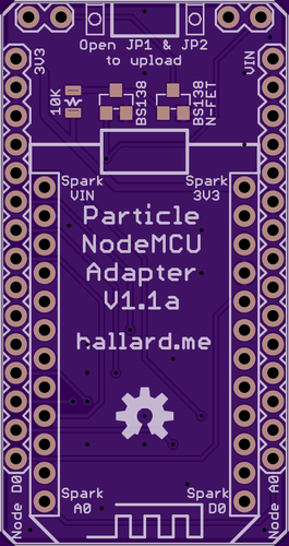
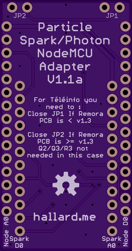
- to be able to handle future Remora PCB version I added the feature to enable/disable Téléinfo FET Staging (they will already be placed on Remora V1.3 PCB) using Jumper J1 & J2.
This page has been updated to reflect the changes and the PCB also, it's now v1.1a.
Boards are still in progress, I did not fully tested them yet, I will update as soon has I got them in my hands. Use at your own risks
Look at the schematics for more informations.
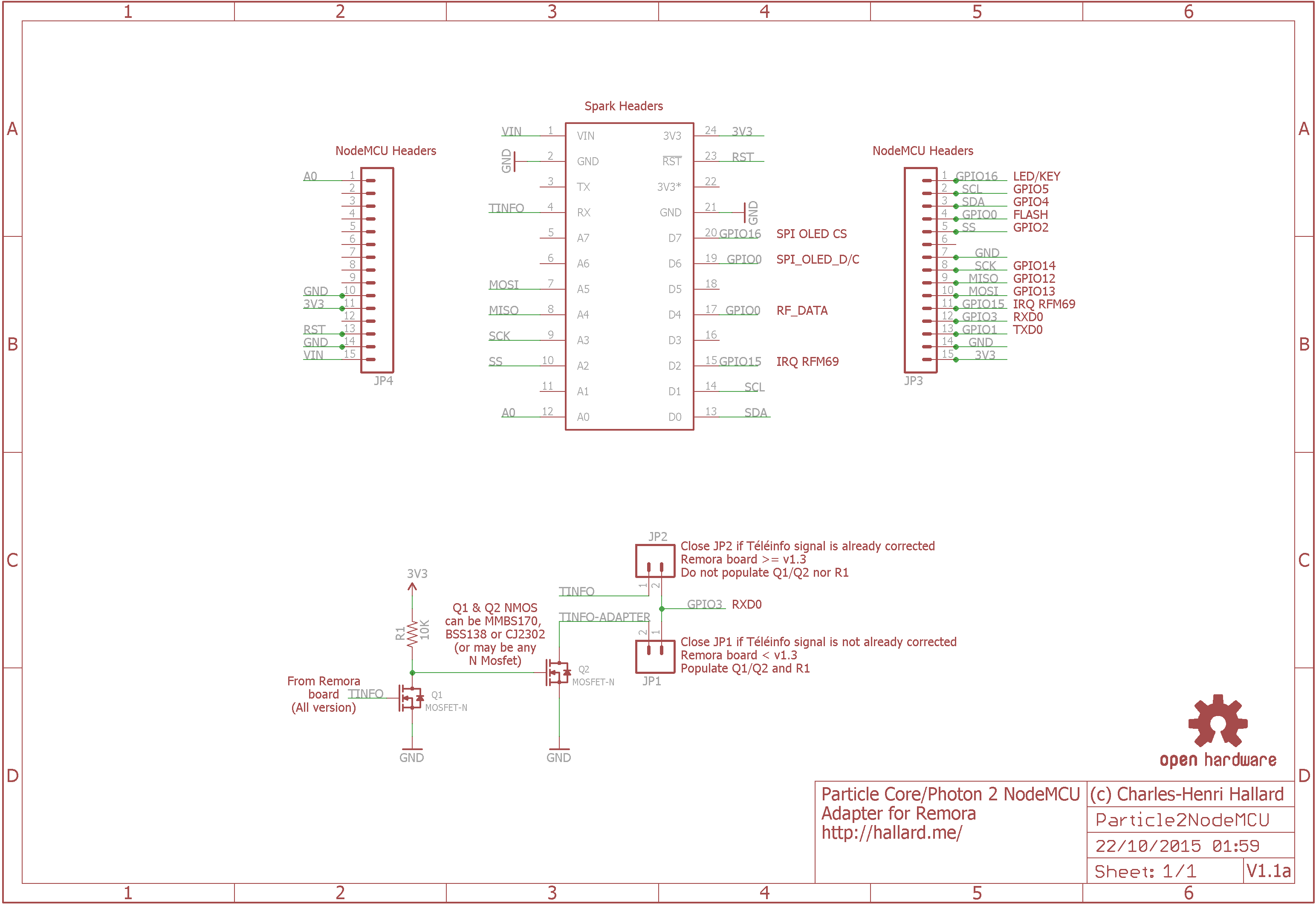
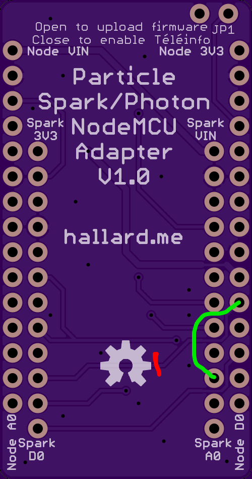
If you have old version V1.0 PCB and a RFM69 attached, here the fix, cut line in red and solder wire on green line.

You can order the PCB of this board v1.1a at OSHPARK
I'm currently waiting for boards from OSHPARK
Boards arrived, still testing before ordering V1.1a boards
##License
You can do whatever you like with this design.
##Misc See news and other projects on my blog