Question on Apple IIc TTL support #209
Comments
|
Apple IIc DB15 <-> RGBtoHDMI 12 way header |
|
So I tried Beta 30 and the text mode was inversed. HGR seemed to be correct. I noticed Beta 31 was out. Switched to that and wow. Works perfectly. This project has allowed me to end my search for retro monitors and not be forced to live with composite video. I can't thank you and the other contributors enough! Analog parts are coming next week for the IIgs. Awesome work! |
Yes, there were a couple of bugs in Beta 30 that stopped IIc support from working. Also Beta 31 added line by line switching of NTSC artifacts so that the four lines of text in mixed modes stay sharp white and don't get artifacts. If you use the analog interface on the composite video output you will get exactly the same quality but the four lines of text in mixed modes will get artifacts as there is no way to automatically detect that mode although full text screens will still be sharp white because the colour burst is switched off. Note for PAL systems, the PAL encoder must be disabled to use the composite output and you may have to manually switch artifacting on and off using long presses of SW2.
The IIgs is unlikely to work properly with the analog interface as that can only discriminate 64 analog levels (2 bits / 4 levels each of RGB) but the IIgs can output 4096 levels (4 bits / 16 levels each of RGB). It should be possible to connect the 12 bits + sync directly to the IIgs motherboard instead to pick up the 4 bits each of RGB instead much like the Amiga and Atari ST but appropriate profiles will have to be created. However there is a further complication with the IIgs because it uses two different pixel clocks, one of 14.31818Mhz to display the Apple II compatible modes and the other of 16.3636Mhz to display the new IIgs hires modes. There is a similar problem with the BBC micro which uses pixel clocks of 12 and 16 Mhz and that is auto detected by looking for a slight timing variation in the sync signals. I don't think that will work with the IIgs but there may be other signals on the motherboard which could be used to infer which frequency is in use but as I don't have a IIgs it is rather difficult to investigate this any further at the moment. Wost case you would have to manually switch between the profiles depending on which mode is in use but that is not ideal. |
|
Ah, ok. Thanks for the information. I wasn't aware of that issue with the IIgs. I have used it with a 15kHz VGA monitor splitting the sync signal as well as with a GBS8220. I was thinking I could just send RGBS to the RGB2HDMI and it would work. If you need someone to do testing, I have a ROM01 IIgs. |
Thanks, that would be very useful. If you are able to use an oscilloscope to look at some IIgs signals that would help a lot. Unfortunately it doesn't look like there is a simple logic level available indicating the clock speed but one possible way might be to look at some of the signals coming out of the Mega II chip (which emulates the Apple II functionality). |
There is likely a way to determine if SHGR or classic Apple II modes are running on the IIgs. There was a clip-on VGC adapter available at one time that gave the ROM3 IIgs HDMI output: http://tulip-house.ddo.jp/DIGITAL/gsdvi/index.html The ROM 01 wasn't compatible since it has a socketed VGC. Looks like the adapter compensated for the horizontal width difference by increasing the border size on the left and right sides in 14.318Mhz mode. |
|
There is this comment on the web site you linked:
So it looks like it is inferring the state from some other signal or signals |
|
Thinking about it, a standard Apple II video line is 912 clock cycles long. AIUI the IIGS VGC video clock is supposed to be 8/7 times the 14.318 Mhz clock which is 16.3636Mhz but if you multiply 912 by 8/7 you get 1042.285 so the line length and thus sync timing may vary slightly in the IIGS modes as it can't use a fractional line length. Maybe that's why it's not reliable as the detection is looking for a very slight sync timing change. |
|
The SHGR modes on the IIgs were a bit fussy to adjust/capture using both the OSSC and directly with a RGB frame-grabber (Epiphan DVI2PCIe). I could get 640x200 mode dialed in pixel perfect, but always had a problem when the machine switched to 320x200 mode and had to re-adjust. |
|
That might be an issue with the 640 pixel modes using a different clock phase to the 320 pixel modes. Something similar happens with an original IBM CGA card where the pixels for text and graphics modes are 180 degrees out of phase so sampling has to be set to 90 or 270 degrees as a compromise value. The Atari ST also has that sort of problem as the phase relationship between the sync pulse and the pixels shifts by 180 degrees randomly on power up so again a 90 or 270 sampling phase has to be used. As I don't have any IIGS hardware this is going to be difficult to investigate any further. |
|
I see what you are saying with the number of colors. With the YUV CPLD, I can get a picture using the Apple II preset but the colors are off, even in the control panel. Cycling through those colors doesn't show up correctly. Red for example does not show up. This is my only IIgs (ROM01) so let me know if you need me to check something. Now that you have solved the IIc and Laser 128, this would be my last display issue to solve. |
|
Logging some info to start with would be useful. Hook up your board to the IIGS composite output as above and display an Apple II compatible mode. |
|
No problem. For clarification, should I use what I already tested, connecting to the 15 pin video expansion or should I make a new cable and connect directly to the composite video out of the IIgs? What would the cable pinout be to connect directly to the composite RCA jack to the analog board? |
|
It doesn't really matter as long as you are getting a locked image as I'm only interested in the sync timing. |
|
Don't know what your use case is exactly on the IIgs. Just be mindful that that composite output is NOT the same as an 8-bit Apple II machine and NTSC artifact color will not work or look right with the classic Apple II video modes. The composite output is a NTSC encoded version of the VGC's RGB output. |
|
Here are the files. I used Copy II plus for the Apple II compatible mode, then I used the super high res test from the iigs dealer diags for the other mode. Let me know if this helps. |
|
Thanks for those. It looks like the sync timing is identical for 14.318Mhz and 16.363Mhz pixel clocks which means that sync timing must always come from the 14.318Mhz clock and there must be a phase discontinuity in the 16.363 Mhz pixel clock during horizontal sync as one line would be 1042.285 clock cycles long. That in itself isn't an issue because the sample clock on RGBtoHDMI is run at 8x the pixel clock and is phase locked to the beginning of each line but the calculation of the actual sample clock frequency will have to be altered to take into account the additional fractional part of the line length. How exactly have you connected the IIGS at the moment? (Which signals & which interface?) I should be able to give you a profile to test 16Mhz sampling with you current connection and if that works then 2 profiles could be created for 12bits per pixel at the two clock frequencies but in order to test that you would have to wire up the RGBtoHDMI directly to the motherboard to pick up the 12 bits directly from the hybrid DACs |
|
I have the 6/8 bit RGBtoHDMI board with the Issue 3 Analog board. I have R,G,B,S, and ground connected to the analog board from the DB15 connector on the IIgs. I haven't fitted the 3rd chip on the rear of the analog board but I can add that. I believe the Apple II profile was selected and I was trying different settings so I am not 100% sure where it stands. I can reset the SD card and try it again if there is a certain profile you would like me to try. |
|
Unzip the attached file, overwrite the existing kernel.img file on the SD card with this one and copy the two AppleGS profiles into: Then program the RGB CPLD and try selecting the two profiles as appropriate: Apple IIGS HR for 14.3 Mhz Apple II compatible modes These are setup for 3 levels each of RGB so you will only get a vague approximation of the source image but the object at the moment is to get a clean image with no pixel jitters or flickering (Like your Apple II compatible screencap above). Best test results will be achieved with peak white images only so if you have a mono SHR test image please use that. As before if you can do two screencaps and a log save and post them that will let me analyse the results. |
|
The GS/OS Finder desktop is a good test for 640 SHR mode. Load up a graphics program like Platinum Paint to test 320 SHR and create test patterns. |
|
I copied the files over from the zip. Reprogrammed the CPLD for RGB and switched to HR to test in Copy II plus. Looks like it couldn't find sync. I also started up GS/OS with SHR and it also couldn't find sync. I tried the auto calibrate but no change. Take a look at the screen caps and let me know what you think. Also, if you have some guidance on adjusting the DAC levels, that would be great. |
|
First try adjusting the DAC-E Sync level to see if you can get the image to lock If you get a locked image you can try adjusting the Hi and Lo levels to threshold the incoming RGB video. The Lo value sets the voltage at which 50% RGB is displayed and the Hi level adjust the level at which 100% RGB is displayed. The Lo value should always be less than the Hi value for each colour. Note the red and blue channels share a setting but the green channel is separate. Run the Auto calibration or manually adjust the Sampling Phase for noise free results. Use the save configuration option after finishing |
|
Messing with DAC-E didn't seem to help. Turning on Sync on G/V and then adjusting DAC-F to even 0.00 got the sync to lock. I tried increasing the voltage a little but wasn't sure how high to set it. I did that for both HR and SHR modes. Colors are still incorrect so I wasn't sure if I should fit the other IC on the back of the analog board now? I took some more captures and saved the log again. Auto calibrate couldn't get the picture perfectly stable and it seemed like the brightness or contrast was too high. I didn't mess with those settings yet. Let me know what you think. |
That probably means you haven't connected the sync input to the right pin or there is something wrong with the sync input on your analog board
It looks like the IIGS outputs sync on green so that's why it works. I can see there are some pixels that are purple which should be white so you probably need to tweak the G Hi and G Lo levels. This would involve soldering a ribbon cable from the 12 way IDC header on the main RGBtoHDMI board directly to pins on the motherboard, specifically the H2, H3 & H4 hybrid DACs which are the yellow resin SIL packages next to the VGC (they look like SIL resistor packs). With your existing board you would only get 9 bits per pixel instead of 12 but most images would look pretty close with only the least significant bit each of RGB missing. If that works OK you will need to get a 12 bit RGBtoHDMI board with 12 bit extender and wire that up instead to get all bits sampled correctly. You would still have to manually change the profile until we found a suitable signal to control auto switching. If you want to try the above, I'll create a couple of profiles for the direct connection and detail the wiring instructions. |
|
Yeah, that sounds fine. I will check the sync coming out of the 15-pin connector on the IIgs. I wonder if that is no longer working. I had it connected to a LM1881 and connected to a VGA monitor which worked fine for a while but then stopped. As you said, it sounds like sync is also going out on green too. I will order the 12 bit board and the extender if you could post the profiles and wiring instructions. They will probably take a couple of weeks to come in. |
|
@timmcross |
|
Here are the profiles for 9 bits per pixel (for your existing board) and 12 bits per pixel (for a new board): Looking at the IIGS schematic, the bit order of the RGB signals is unclear as the 12 bits coming out of the VGC are only labelled Vid0 - Vid11 It is likely that pins 2-5 of H2 are the blue bits, pins 2-5 of H3 are the green bits and pins 2-5 of H4 are the red bits but I'm not sure which end is the most significant bit (i.e. is it 2,3,4,5 or 5,4,3,2) so you will have to do some investigation and experimentation. For 9 bit per pixel connection with your existing board: DO NOT USE THIS WIRING FOR THE 12BPP BOARD AS THE WIRE NUMBERS ARE DIFFERENT! Red Channel Green Channel Blue Channel Sync GND +5v I suggest wiring up just one of the RGB channels plus the other signals first to find out which order is correct. Wiring up the 12 bit version is very similar but uses all 4 bits per RGB and the wire numbering is different as the extra 4 bits are wires 1 - 4 and the Vsync input is not used as one of the green bits. |
|
OK thanks for the info. I have ordered the 12 bit boards. I also checked the connection and found that the sync wire I was using wasn't making the connection. I replaced it with a different wire and was able to turn off sync on green. Not sure if you need me to send you more screen captures or logs at this point. While I wait for the boards, I will look into wiring up to the DACs on the motherboard. It doesn't look like it would be that hard. It might take me a few days though as things are coming up. Thanks again for the guidance! |
|
It would be useful to wire up your existing board as a 9 bit test so we can determine if it's going to work at all before wasting any time building up the 12 bit boards. (That would also determine the bit order so I can finalise the 12 bit wiring instructions - the first option in my RGB instructions above is the most likely bit order) I've implemented manual switching between the 14Mhz and 16Mhz timings by pressing SW3 so even if we can't get auto switching working it will be easy to toggle between the two modes without having to call up menus. BTW do you have an oscilloscope? That would be useful for looking at potential signals to use to determine if a 14Mhz or 16Mhz mode is in use. |
|
Sure, no problem. It might take me a few days to find time to tear my GS apart but I will see what I can do. And I recently purchased an oscilloscope so let me know what you need. |
|
There is a new Beta 33 release on my fork which has all the recent changes consolidated. This will likely be a release candidate for the next stable version unless bugs are found so could you check it is OK for you (Some minor changes since the version above): |
|
I copied beta33 over and booted up with that. Everything behaved as before. After seeing posts about the sparkling on the Tandy, I think I see something similar in SHR. I see black and white dots popping up every so often. It was worse before I auto calibrated it. I also have the PI powered from the IIgs. I could try to go back to it's own power supply. It doesn't bother me too much but I haven't used it for that long. I tried to capture it on video. Let me know if you can see it. |
|
Try going into the settings menu and increasing the overclock core by 10 or 20 or even more but high values may require a heatsink on the Pi zero. Changing to external power is very unlikely to change anything as this connection is all digital. The issues with the coco are due to marginal analog signals. Any problem here is due to the Pi not being quite fast enough. |
|
Sorry for the delay. It looks like with the extender board, there is very little room for a heatsink on the PI. I tried increasing the PI to 10 and 20. At 20, it seems that the dots are still there. I noticed the PI was up to about 45 degrees. At what temperature would it be too hot? I think the PI zero and 3 both share a similar processor so I will try it with a PI3 and see if I notice any difference. For me, I can ignore these dots. Let me know if there is anything else you would like me to try. |
Mine run at 55 degrees so 45 is no problem. Most Pi zeros will overclock core up to 140+ without a heatsink although some won't. The system doesn't run very well on other Pi models so don't bother, it won't work. Anyway, please try the latest beta 36 After trying auto calibrations at various multiplier settings, go to the info menu and use the save log function and post the log.txt file from the sd card. Maybe record a video of the calibration running as well? Are the dots all across the screen evenly or just in vertical bands? (i.e. clean areas and noisy areas). (That would point to an incorrect geometry setting) |
|
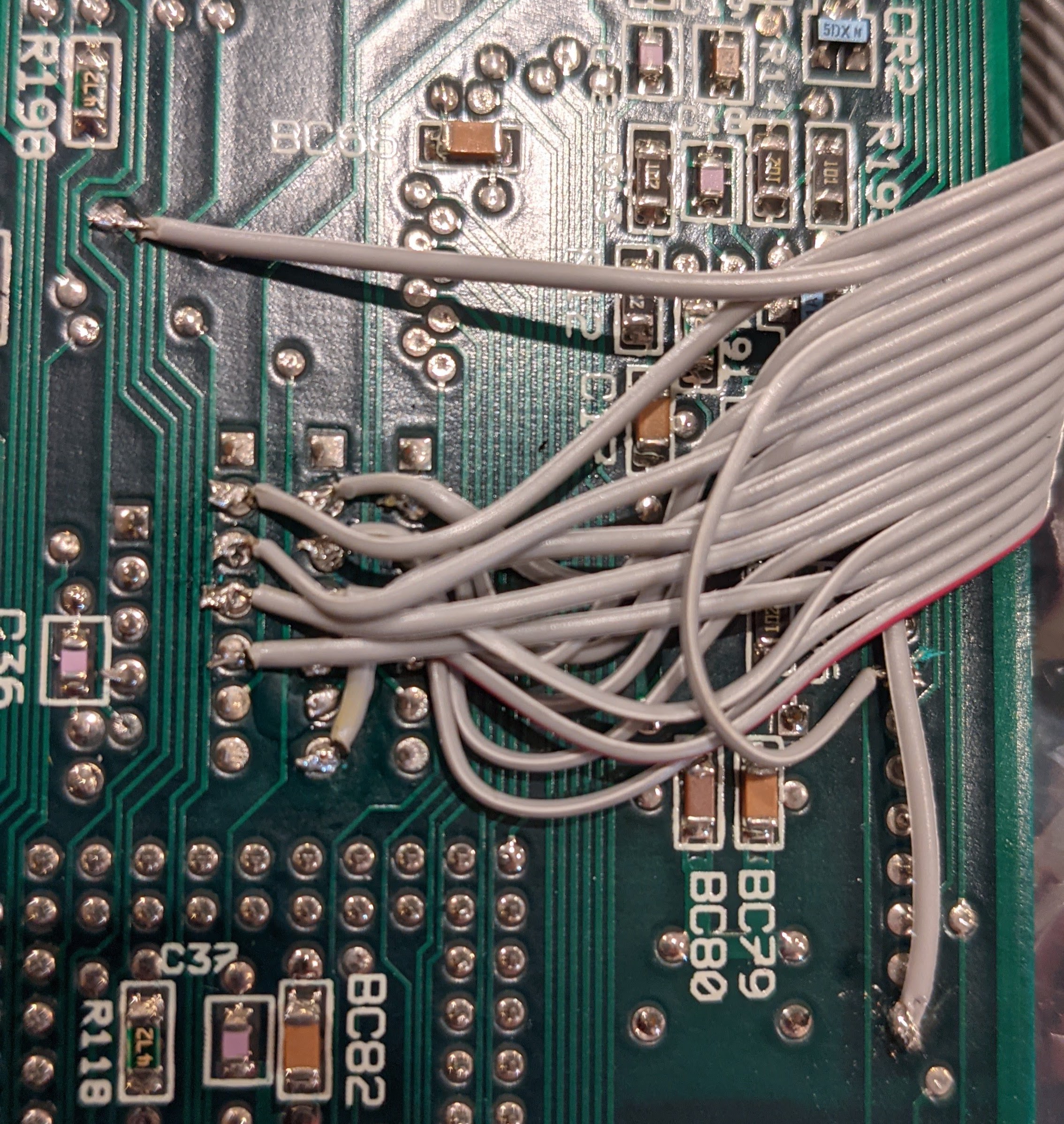
i'm going to cabling my IIgs, but not sure about wiring... from wich side i'd start counting pins in the resistor arrays? can someone post a pic of soldered cable? |
|
The square pin is pin 1. Here is a pic of the cable I soldered on. The red stripe is pin one on the cable. |
|
Thank you very much @timmcross , so you used (was my first doubt) the bottom side of the board for soldering... but i can't see which point you used for vsync (wire 14)... can you tell me? |
|
@timmcross sorry for previous message, i noticed now you used only 15 wires! (i usually connect the 5v for powering rgbtohdmi). |
|
Actually, pin 14 needs to go to the VGC so I used the TP at the top of the picture, under R198. I believe I have pin 16 connected to pin 10 on H1 for +5v power. |
|
it works for me with beta 36, and auto calibrating works too. |
|
made furhter test, i got noise, vertical dots and lines after a minute or two i power on the IIGS. Tried with overclocking cpu and ram by 10, situation is a bit better, but artifacts are still there. Higher overclocks seems even worse. |
@aotta Are the bars of noise moving up or down the screen? @timmcross This type of noise looks a bit like a crosstalk effect or even a power supply ripple problem. If you can get the noise to happen on a solid colour screen, would it be possible to look at the RGB bits with an oscilloscope to see what level the voltage outputs are and if the noise is visible (might be spikes / ripple or the voltage levels out of the VGC are too low). |

|
No, what I am seeing are individual pixels flashing black and white on different areas of the screen. They are very scarce and spread out. I am getting a HDMI to CSI2 adapter tomorrow so I can use another RPI to capture the screen. My phone wasn't picking it up very well last time. My ribbon cable is about 6-8 in long. |
|
Have you tried beta 36 (with CPLD update) |
|
Sorry, for the delay. Just updated to .94 tonight. I changed the multiplier to 10x, auto calibrated, and I think that did the trick. I saved some of the logs. Let me know if that makes sense. I will still try to capture video tomorrow. Just curious, what does the clock multiplier do and on a side note, what does DVI Compatible do to the signal? I assume it is used when you are using a HDMI to DVI cable? |
The clock multiplier is the value that the pixel clock is multipled by to produce the sampling clock. There are a range of multipliers because the CPLD can only run up to a certain speed (about 170Mhz) and if you exceed that speed it will stop working, so higher pixel clocks must use lower multipliers. Using a x10 clock will result in a sampling clock of 163.6 Mhz (16.36 * 10) which is close to the max the CPLD can handle. DVI compatible mode allows the Pi to work with both older DVI and newer HDMI monitors by outputting a DVI signal which HDMI monitors should cope with but some HDMI capture cards don't like DVI mode so you have to switch to full HDMI when using them. BTW did you still get the bad pixels at x8 with the new software? |
|
At 8x after the firmware update, it didn't seem different. Going to 10x and auto calibrating seemed to help. I will check again tomorrow. |
|
@IanSB i can confirm that, with x10 multiplier, the issue left are (almost all) related to "flashing" solid colours (they don't scroll on the screen, but appears randomly and disapperar, varying intensity with a sort of flashing effect). |
|
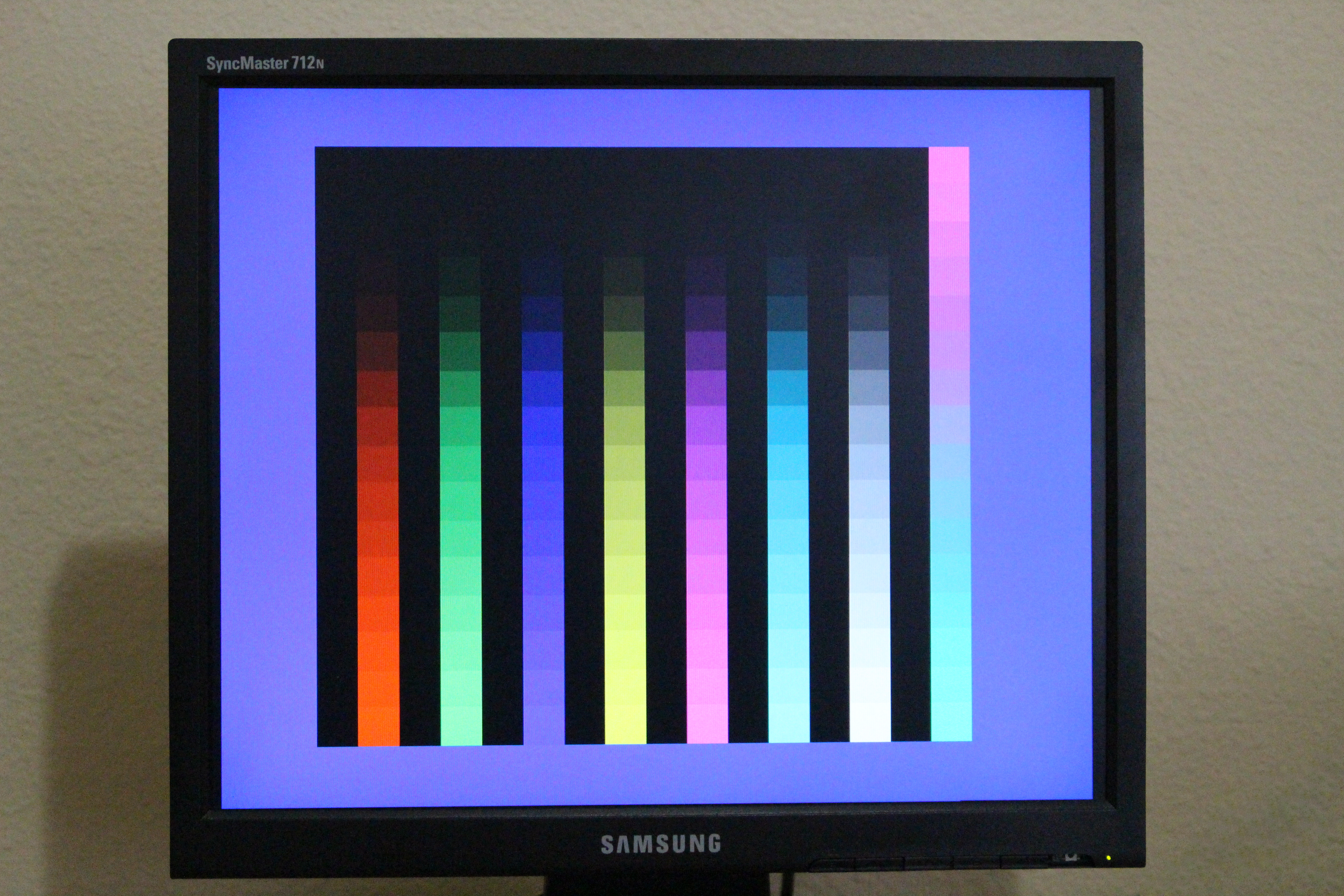
wondering if i left some bad soldering in cabling, i played again with the MT test screen that Ian posted above, and noticed a persistent issue in hires screen with colors border: |

I don't think there isn't any way for RGBtoHDMI to make an error like that. Your image is a 16.3 Mhz SHR mode but the other one above is a 14.3 Mhz Apple II mode. The SHR modes are 8 lines higher than Apple II modes and that big white line corresponds to that height so I think it must be a software problem with the test program when switching between the two modes and the way the border is setup.
Yes, I think the main issue is ripple in the power supply so you do need to recap it. |
|
Can you also try at x6 multiplier as well. |
|
Hi there. here is a screenshot at x6. It is not pretty. Think x10 is better than x8 but I will have to try it for a longer period of time. |

|
Did you re-run the auto calibration? (You have to do that after a multiplier change) |
|
I tried it just now and I couldn't get a clear picture at x6. This was the best one but it had black dots all over it. |

|
Yes, it looks like it needs x10 |
|
Can you set the multiplier to x10 and run an auto calibration in both 14Mhz and 16Mhz modes (you will have to set the multiplier for each mode) and post the saved config which will be in Saved_Profiles on the SD card. I'll include the calibrated version in the next release. |
|
Here you go. This is a profile with both modes set to x10. I think x8 worked OK for Apple II mode. Let me know if you would like to see a profile with x10 for IIgs and x8 for A2. |
I noticed Apple IIc TTL support in Beta30. Is that for the non-plus version? If so, that sounds awesome! What would the pinout be from the IIc to the RGB2HDMI?
The text was updated successfully, but these errors were encountered: