Road Generator | Development of simulation environment in Unity based on OpenDRIVE file to simulate vehicle behavior and point cloud data

Game engines can be used for the validation of environment simulation, vehicle dynamics, and complex AD algorithms in different scenarios. The goal of this project was to create a simulation environment in Unity3D using the predefined OpenDRIVE file to simulate vehicle behavior and point-cloud data gathered by perception sensors. This research work focuses on the development of a road generator application for creating a road structure and corresponding visualization data in a driving simulator. The application is based on the OpenDRIVE file, which is a standardized file format. The OpenDRIVE files contain a dataset that describes the road structure and covers all the properties regarding road geometry.

To display the road and its environment in Unity, EasyRoads3D toolset which contains dynamic crossing prefabs and side objects, such as bridges, guard rails, traffic signs is used.
Several standardized file formats have been developed in the automotive industry for companies that require similar datasets for their simulators, including road networks and road objects. One of the most prominent standardized file formats developed by VIRES is OpenDRIVE.
This file format was created in order to simplify the exchange of data between simulation programs and companies. The OpenDRIVE standard was recognized by many companies after the first public version was released in 2006. OpenDRIVE stores data in an XML format. In the XML file, nodes indicate various properties of the road, including intersections, elevations, and lane parameters. The figure below shows the hierarchical architecture of OpenDRIVE.

Geospatial data needs to be represented in various ways, including mapping and visualization. Therefore, a suitable type of data and object representation must be provided by the geodata models. In OpenDRIVE, the geometry of road segments is derived analytically from the chord line and the track coordinate system. In simulators, road layouts must be visualized relative to the center of the 3D world.

OpenDRIVE describes the layout of each road segment using geometric records based on its types, such as lines, arcs, and spirals.
The following information is contained in each record:
• An s offset,
• A world coordinate which defines starting point,
• A heading angle which describes the initial orientation of the road segment (In OpenDRIVE standard, heading angle is defined in terms of radians.)
• The length of the road segment.
Further, each geometry record contains an attribute that describes the type of geometry.
Geometries can be divided into several types:
• Lines – have no additional parameters
• Arcs – have a constant curvature parameter
• Spiral – have two curvature parameters for the start and end of the segment

-
Line Geometry : In case of a line geometry as shown in the above figure, its ending points can be found using the following equations:
• xEnding = xStarting + cos(hdg) ∗ (sEnding − sGeom )
• yEnding = yStarting + sin(hdg) ∗ (sEnding − sGeom )
-
Arc Geometry : Arc geometry is bit more complicated that the line geometry. By using curvature parameter, the radius of the arc can be computed as:
• radius = | 1 / curvature |

Since the initial heading angle and arc radius are known, the center of the arc can be computed depending on the curvature sign:
• xArc = xStarting + cos (hdg + ( (pi/2) * Sign * (-1)) − π) ∗ radius
• yArc = yStarting + sin (hdg + ( (pi/2) * Sign * (-1)) − π) ∗ radius
To compute the central angle of the arc in terms of radians, the following equation is used.
θcentral = length_arc / radius

As can be seen in the above fiure, the RoadGenerator application has several subcomponents that handle different tasks, like parsing and reading XML file, getting node attributes, etc.
The RoadGenerator application is responsible for creating the segments of the road geometry, which is described in OpenDRIVE file, in Unity platform. Below figure indicates an overview of RoadGenerator application's flowchart.

To be able to use the assets of EasyRoads3D toolset, it is required to create instances of ERRoadNetwork and ERRoadType classes. Moreover, the roadWidth and roadMaterial.

Based on the order of geometry nodes in OpenDRIVE file, the Lineroads and Arcroads containers individually hold the road segment assets as a list. Likewise, the linePaths and arcPaths hold road geometry parameters such as, starting points, ending points, heading angle, etc.

parseFile function deals with reading the file in given directory and selecting the nodes based on the desired tag name which is geometry. It returns those nodes in a list.

In the OpenDRIVE file, the geometric parameters of road layout are represented as attributes of child nodes under geometry node. To be able to perform arithmetic calculations by using attributes, it is required to convert them from string to float format. As depicted in the below figure, the attribute format is converted from string to float.

All types of road geometries have common parameters such as starting points in X and Y axes, road segment id, to describe road geometry. Therefore, an abstract class which is named paths was created to hold these information as its variables. Other classes which are responsible for holding information about relevant road type like, LinePath and ArcPath, are derived from the paths abstract class.

The constructor of LinePath class performs to compute ending point of a road segment based on the given starting point, road length, and heading angle. Both starting and ending points of road segment are stored in a 3D Vector to be used for creating game objects in Unity via EasyRoads3D toolset.

In addition to the arguments taken by the LinePath class' constructor, the constructor of ArcPath class also takes the curvature parameter as an argument. By doing so, it acquires all parameters required for computing the starting point, final point, central point, and the points between starting and endpoint.

To visualize road segments in Unity platform based on the calculated points, the assets of the EasyRoads3D toolset are used as game objects.


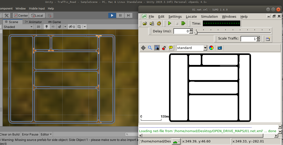
We compared the road network generated in Unity with the SUMO simulator to determine how accurate the road generator can create road networks. The below figure indicates the comparison of the road networks simulated in different platforms.