Broken example (?) #93
Comments
|
@Peque I get the intended result (cylinder with rectangular hole through it) in FreeCAD 0.16 revision 6710.
In the top menu if you go to Help->About FreeCAD it doesn't show a revision number? |
|
@jmwright It does not show a revision number (says "Unknown"). I will try to compile from source instead of installing from the official Fedora repositories and see what happens. Thanks and feel free to close this issue. 😊 |
|
Will the AppImage in this link work in Fedora? |
|
@jmwright I am afraid not. I will try to compile from source when I have some time and report back if things are still broken. |
|
Ok. I'll close this issue for now. Feel free to reopen if needed. |
|
@jmwright I just compiled it from source. Tried with the With Do you have any idea about why could this be happening? Do you know how could I try the same version you are using in Ubuntu? PS: using |
|
@Peque What version of Fedora are you running, and is FreeCAD in the standard repo? I'll set up a VM to see if I can replicate your issue. |
|
@jmwright Latest (Fedora 26), fully upgraded ( If you want to compile FreeCAD from the Git repository, you can install dependencies with: And then compile with (I guess you already know this better than me): 😂 Thanks a lot for your help and tell me if I can be of any further assistance. 😊 |
|
@Peque I have a Fedora VM set up and can replicate your results now. I'm not sure why this is happening. When I create your object manually it works fine. It's probably got something to do with a wire not being closed properly. One work-around you can use to keep moving forward would be the following. import cadquery
from Helpers import show
# result = cadquery.Workplane("front").circle(2.0).rect(0.5, 0.75).extrude(0.5)
result = cadquery.Workplane("front").circle(2.0).extrude(0.5) \
.faces(">Z").rect(0.5, 0.75).cutThruAll()
show(result)Depending on how you want the object to change as you alter the parameters, that may or may not work. I think it will work for most cases though. I know it's not a full solution, but does this at least make it so you can finish your script and get what you need? Have you tried FreeCAD 0.17 in Fedora? I'm curious whether that would work or not. |
|
@jmwright Yeah, do not worry, I already used a workaround which works well (code does not look so good though 😂). Anyway, happy to see that you can at least reproduce the same issue. I tried with FreeCAD 0.17 as well ( Thanks for your help. 😊 |
|
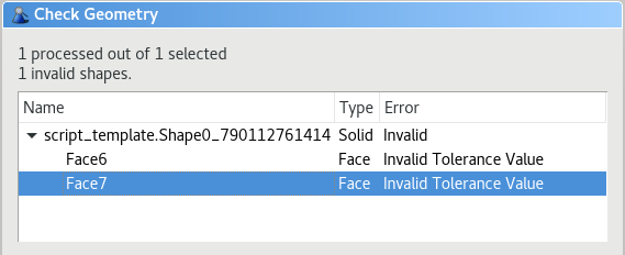
When I set FreeCAD up so that I could do Part -> Check Geometry, I got the following.
Face6 is the bottom face of the extruded solid, and Face7 is the top. I checked the 2D wires separately, and they don't show any errors. There's something with how we're using FreeCAD's extrude operation that's introducing the problem. I tried changing the options to our extrude operation and it didn't help. The problem must be closer to the FreeCAD object level. |
|
@RustyVermeer Looks like it. Thanks for catching it. @Peque - Rusty recently implemented a fix for this. I know it's been a long time since you've reported it so you may have moved on, but if you grab the latest master (install/update through the 0.17 add-on manager) you should be all set. |
|
@jmwright It seems with the latest changes this works fine: import cadquery
from Helpers import show
result = cadquery.Workplane("front").circle(2.0).rect(0.5, 0.75).extrude(0.5)
show(result)However this (changing import cadquery
from Helpers import show
result = cadquery.Workplane("front").rect(0.5, 0.75).circle(2.0).extrude(0.5)
show(result)Note that I am using FreeCAD 0.16, not 0.17. The stock Fedora 27 version provided with the official repositories. However, when I last tried with 0.17 I was able to reproduce the same results. |

|
I can replicate this behaviour as well. As a matter of fact, this has been true for some time. When I first encountered it, I didn't think it was a bug, and that's still a question on my mind. @jmwright, is this behaviour as expected or not? When I make the .rect larger than the circle, things behave as we'd expect: So, what seems to be happening is that the first wire added to the cq object is considered as a face. Then, subsequent wires are checked. If they are smaller than the first wire, they are correctly combined with the face and result in a hole when extruded. If they are bigger than the first wire, they are treated independently, and will be extruded as their own face. This is what we see in your sample, @Peque . So, in short:
|

|
We definitely need to fix this. It's not the intent to require the user to draw things in the correct order. Does this problem persist even after the recent validate() addition? |
|
Yes, this persists. There is an assumption stated in the sortWiresByBuildOrder function stating:
Which implies that we think the wires are already sorted before we call that sort function. I'm a bit confused by that, so if there's something I'm not aware of, let me know! This function is used in the _extrude function, so I think that's a good place to start poking around in. I'll see if I can find anything out... |
|
@RustyVermeer yeah I remember that now, you're right. We need to move towards just letting all of the edges generated by the user accumulate, and then organize them into wires at the end, right before the extrude. I say this because when we import geometry from DXF/SVG, we have to do that anyway, so why not use the same code path for manually generated geometry as well? What will still be missing is a way to sort from outer to inner-- but again, we'll face that with imported geometry anyhow-- there wont be a reliable way to force creation order when we're reading geometry from a file... |
|
First thought for sorting wires is this:
Anyway, that's just rough thinking. As for this particular problem, I have a proposal to solve it: If you run that in the CQ module in FreeCAD, it should work, even if you swap the .rect and .circle around. What I've done is copy exactly the code from _extrude and the only change I made was turning this: into this: What are the thoughts on this? I don't think it will interfere with anything else to just bypass the sort, especially because it appears that the extrudeLinear function will handle this anyway (when it turns wires into faces) |
|
@RustyVermeer
So are you saying that our current extrude function is basically double sorting the wires? Is that the source of this problem? |
|
Well, sort of. Our sort function has a check That failure then results in the function returning a list of lists, where each inner list has only 1 wire. incorrect extrude behaviour arises from: correct behaviour arises from: Now, bypassing the sort function will leave all wires in one list. Then, when we do a linear extrude, we convert a group of wires into a face. It appears that So, we could either change the logic in the sort OR rely on the FreeCAD .Face() function to create the face from a list of wires for us. We already do rely on the .Face() function for this anyway, if I'm understanding all the code correctly. |
|
As I think it is a separate issue, I created #113 just to track this. |
I spotted a weird/unexpected behavior when displaying an object I was making with CadQuery. "Debugging" this issue led me to one of the CadQuery examples:
Which results in:
If I change the
.circle().rect()to.rect().circle(), then I get:Is this expected? Can you reproduce this issue?
Using
cadquery-freecad-modulev1.0.0.1 and FreeCAD 0.16 (unknown revision, installed it from the official Fedora 26 repositories).The text was updated successfully, but these errors were encountered: