GROVER is a multi-purpose remote controlled rover that features a web controller, a camera to stream video, an optional radio controller for internetless control, a microphone and speaker to allow communication to and from the controller, an automatic braking system using LIDAR, and other sensors that are recorded onto a server and can be viewed as graphs. The camera can be used to steer the rover to not bump into anything and for navigation purposes. The speaker and microphone allow a remote user to communicate with someone who is next to the rover.
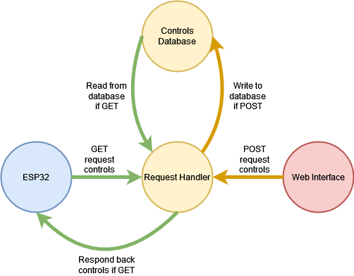
Four components come together to allow remote web control over chassis movement: an ESP32 on the rover, a database on the server, a request handler on the server, and some Javascript code to be ran on a browser (from this point onward the browser side will be referred to as the web interface). The database stores a single table, ‘controls’, and ‘controls’ stores a single row made up of four columns: ‘up’, ‘down’, ‘left’, and ‘right’. Each column stores an integer value that during runtime should only ever be a one or a zero, making the value stored at that column more like a boolean than an integer. This database stores the state of the directions from the web interface. The request handler’s job is to either update values in the database from a POST request or respond back with a four character string of ones and zeros which it builds from values stored in the database when it receives a GET request. The Javascript code that runs on the web interface sends POSTs requests of the state of the arrow keys to the request handler so that it may update the database. The ESP32 on the rover constantly GET requests the server and receives the four character string response of ones and zeroes. It parses the string and updates the throttles of the motors accordingly, reflecting the input from the web interface to the chassis.
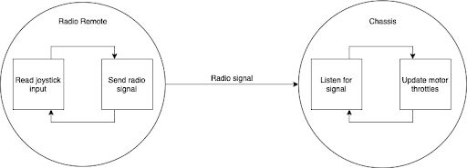
Two different modules are in play to get the radio communication to work between the two ESPs: RadioRemote, which is used on the remote control and reads input from a joystick, and MotorController, which not only reads inputs from the remote, but also communicates with the web controller, ultrasound sensors for automatic braking and interfaces with the motor controllers for turning and reverse logic.
To send inputs from the joystick to the rover, a protocol was developed for remote-rover communication. Ultimately it was decided on this binary format for sending data:
| sync byte | input type | msb | lsb |
|---|---|---|---|
0x45 |
'x' |
0xXX |
0xXX |
0x45 |
'y' |
0xXX |
0xXX |
0x45 |
'b' |
0x00 |
0xXX |
Where 'x' indicates its sending the uint16_t value read from the joystick's x-axis, 'y' corresponds to the y-axis, and 'b' is a 1 or a 0 which corresponds to whether the button is pressed or released.
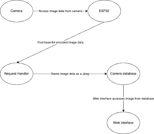
The camera system consists of a dedicated ESP32 interacting with a server and the web-interface interacting with the server. The wiring of this system can be seen in the wiring diagram. The ESP connected to the camera is labeled as “ESP3”. We chose to connect this ESP to just this camera so that the video streaming has the least possible delay and highest frames per second.
The system works by first taking a picture of resolution (120 x 160). Then the ESP32 obtains the image data, and encodes it in base-64. To maintain space efficiency, we base-64 encode every 3 hex digits we see and append them to a larger array as opposed to base-64 encoding an entire unprocessed array of the image data. If we get to the end of the image data and there isn’t enough data for a triple, we simply pad with “=”.
Once we base-64 encode the image data, we send a post request to our team server. Once the image data is received, the server’s request handler takes this image data and decodes it and uses this decoded data to create an image called “grover_image.jpeg.” In other words, the base-64 encoded image data isn’t saved. Instead, we create an image out of this data and save it. Additionally, we take many pictures and as a result send many post requests. The result of this is that the server replaces the last “grover_image” with the new one received from the esp32. The server thus only has to save one image.
This entire process is repeated inside the ESP32’s loop function; the camera takes a picture, the ESP32 applies base-64 encoding to the data and post requests it, the server takes the data, decodes it, and saves it as the image “grover_image.jpeg.”
The result of this repeated process is a method to achieve video streaming. By accessing the tlast saves “grover_image” at this link, one can obtain the most recent image. If this accessing is repeatedly done while the esp32 is constantly posting images, then by constantly displaying the most recent image you get video streaming.
The web-interface displays video by constantly accessing this image in the server and displaying it so that we get a video stream of what the rover sees.
The audio system consists of two almost-identical ESP32s interacting with a common server. One ESP32 is placed onto GROVER and another onto the radio remote controlling it. Its behavior emulates that of a walkie-talkie system.
The physical wiring for an audio ESP32 can be examined in the wiring section of the diagrams as “ESP2”.
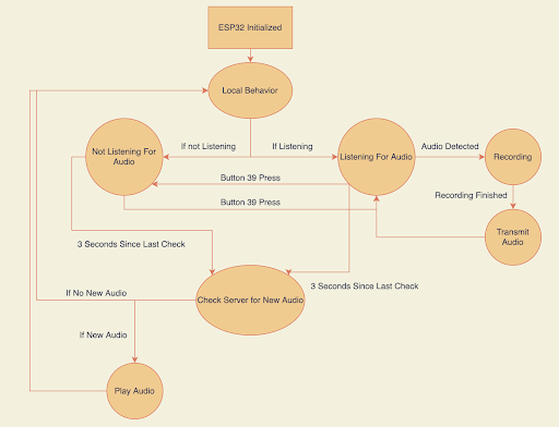
The controller ESP32, upon initialization, is set not to listen for sound. This can be toggled by pressing a button connected to pin 39. While listening, the ESP32 will begin recording incoming audio if the noise levels exceed a threshold ratio of 3000/4096 on the range of possible voltages input to the microphone's pin. Once a loud enough noise is detected, the ESP32 will continue to record audio at a rate of 8,000 Hz until either a second has elapsed without "loud" audio or five seconds have passed, whichever happens sooner. While recording the audio, the incoming microphone data is both mulaw and base64 encoded and appended onto a string to be delivered to the server when ready.
As each ESP32 has a unique URL which it targets on the server, the server is easily able to distinguish the two different sources of audio and appropriately log the transmitted audio into a database containing only other encodings from the same device.
When the ESP32s are not actively recording audio, they ping the server on a regular three second schedule for a new encoding from the other device if any exist. If new data has been posted since the last check, the server will return the most recent audio clip. The ESP32s will then decode the base64 encoding and DAC write the yielded values at the same telephone frequency at which they were recorded onto the wired speaker. This will play a slightly lower-resolution version of the original clip due to hardware constraints.
The rover and controller ESP32s are very similar and vary in the fact that since space was limited on GROVER itself there was no room for the button attached to pin 39 on the controller. As a result, there is no toggling of whether the rover is listening so it will always try to record and transmit audio if it hears anything loud enough. The rover also varies in the fact that there exists a tft display on the controller, which always shows the ESP32's current state. This was also dropped from the rover ESP32 in the interest of space. Other than that, and the fact that the two ESP32s target slightly different files on the server, their functionalities are identical.
The automatic braking feature utilized sonar which was wired to the same esp32 that controlled the motors while the other sensors were utilized by a separate esp dedicated to them. This was implemented to prevent a time lag from the get and post request that the sensors did to the database that stored their data or different api’s that could cause a delay in input reception of directional commands to the motor controller.
The sonar data was interpreted via a module called HCSR04.h by Martin sos that allowed for the measurement of the current distance of an object. It does this by first initializing a distanceSensor in the module with parameters triggerPin and echoPin which were ports 13 and 34 respectively. The distanceSensor has a function measureDistanceCm() which measures the distance of the perceived object in centimeters and if the object cannot be read as the signal was scattered or it was too far away it returns the float -1.00.
Using this input the objective was to make it so that if an object was within a certain variable threshold, which we set to 15 centimeters, the rover would not be able to move forward but would still be able to move backwards and turn. Thus, in each loop after the input values for the motor were received there would be a conditional check on whether sonar beneath the threshold and positive (-1.00 was a possible output in which we would not want to stop) and if so only allow the command of the motor to pass through if it was not forward otherwise it would stay stopped. This functionality is extended to both the website sent commands and radio controller.
The other sensor data was wired to a separate esp32 and it sent up data to the server to be stored and plotted. The data from the bmp ( Temperature (Celsius) and Pressure (pascals)), the gyroscopic data (angular velocity) acceleration data in the x and y direction were all captured directly on the esp32 and sent to a database for storage along with date-time for when the server received the data. Other data such as the altitude and current location relies on sending requests to apis to get the information. For the current longitude and latitude location the esp32 does a scan of the wifi networks and uses the information of that scan to send a request to google’s geolocation api that uses wifi localization to determine the current location of the rove. This location in longitude and latitude is also used to send to the weather.visualcrossing.com api to request the current pressure from the given area. This pressure was used to tune the bmp’s altitude reading which would compare the pressure difference between the api’s reading to its current reading to determine the altitude. This weather api request only happens once in the setup loop for the code so that there are no excess api requests that return the same data.
Finally, the velocity in the x and y directions were derived via a discrete time step integration which kept track of the time between readings, the previous velocity, and the current acceleration to derive the current velocity. There also had to be a threshold set to attempt to prevent the velocities from drifting immediately due to compounded inaccuracies in the accelerometer. This was set to a threshold of the absolute value of acceleration of at least .75 in which only then would the total velocity be changed.
All of these values were then sent up to the server where they were then converted into plots of the last 10 readings when viewed in the interface.
The current location can be viewed via a different script which displays the last uploaded location of the rover.
The main body of the chassis where everything-motors, microcontrollers, wiring, power supply-was secured to is a 22cm by 28cm wooden board. Breadboards, power supply, and wiring were secured using tape. Motor Controllers meanwhile were fastened using screws. Four motors were attached to the main body, two on each side, using two zip ties each to line them up and hot glue to permanently secure them to the main body. Each motor had a rubber tire secured to their shaft so that the tire may be run by the motor. Each tire is 88cm in diameter. To secure the tires to the shafts, a universal shaft hub first was slid onto the shaft and screwed on tight. The universal shaft hub featured threads that were offset from the axis of rotation. This allowed two screws to go through the tire first to then be linked up with the thread, securing the tire to the motor shaft.
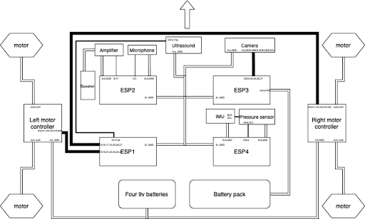
In total, four ESP32s and its peripherals, two breadboards, a battery pack, four 9v batteries, and two motor controllers were used in the wiring of the rover. The wiring of each component is detailed in this table:
| component | role |
|---|---|
| ESPs | Reads input from the peripherals and controls the throttle of the motors. |
| Battery pack | Used to power exactly one ESP through its micro usb port, which then powers the rest. |
| Four 9v batteries | Used in parallel to power the two motor controllers via direct connection, a switch is used to toggle power. |
| Motor controllers | Wired directly to the motors (1 motor controller -> 2 motors), controls the throttle and direction. |
| Two breadboards | Holds the four ESPs, power rails are used for carrying 5v to each ESP. |
A diagram of the wiring is shown below.
- GET requests to server/chassis/server.py and if successful receives a 4 character string response of ones and zeroes, telling the chassis which directions are being pressed on the web interface
- Uses the ‘WiFI’ class to connect to a network and the ‘WiFiClient’ class to connect to a host to send HTTP requests to and listen for any responses back from host
- Code on the chassis that receives bluetooth communication from the radio controller.
- Uses the
SerialBTclass to simply read incoming bytes while they’re available, following the protocol described above.
- Contains helper functions to make chassis movement and control more intuitive, specifically runLeft and runRight which each take in only a throttle from -1 to 1 to run each side respectively
- Initializes pinouts for all 4 chassis motors
- Glues together web controls, radio controls, motor api and automatic braking into one file.
- Detects via external switch whether or not it should listen for radio or wifi input.
- Request handler which supports GET and POST requests
- Responds to GET requests with a 4 character string of ones and zeros from a database which represents the states of the arrow keys on the web interface
- When receiving a POST request, it updates the database for every direction specified by the form of the request, if successful responds with a ‘POST Successful’ message
- POSTs state of arrow keys from web interface to server/chassis/server.py every time a key is initially pressed or initially released (prevents sending redundant POST requests)
- Used by index.html
- Code for the transmitting end of the radio communication.
- Does not attempt to connect to any bluetooth devices and simply sends out whatever input it receives from the joystick in the protocol described above.
- Code for posting base-64 encoded image data to our team server
- Works by constantly taking photos, encoding them, and posting (In the loop)
- Code for sending http request and base-64 encoding a char array
- Server code that contains post and get requests for image data
- Post requests are sent by the ESP32 in “x-www-form-urlencoded” format with data as a key. This data key contains the base-64 encoded hex image data that the ESP32 obtains. The request handler takes this data, and creates an image out of it and saves it to the server in a file called “grover_image.jpeg”.
- By saving the image in each post request, the web interface can just constantly open the image in the server at this link which results in video streaming.
- Contains FSM logic to check for, record, and transmit audio from GROVER to the controller
- DAC writes to wired speaker to play sound
- Instructor code to be able to base64 encode and decode mu-law encoded voltage values
- Mirrored version of chassis_audio.ino for the controller instead of GROVER
- Utilizes TFT screen for live status of ESP32’s tasks
- Utilizes additional button to be able to toggle listening mode
- Receives and logs audio encodings from remote_audio.ino
- Provides chassis_audio with new encodings when requested
- Mirrored version of from_controller.py for the controller instead of GROVER
- Receives and logs audio encodings from chassis_audio.ino
- Provides remote_audio with new encodings when requested
- Code for the esp32 on the rover that reads and sends the sensor values up to the servers
- This code upon setup sends out a get request to the google geolocation api and then uses that location to get the current pressure via the weather crossing api
- In the loop it records the acceleration in the x and y directions, the angular velocity in the x and y direction, the current temperature, pressure,and altitude (derived from the pressure reading goten from the api request). It sends a post request of this data every run through the loop
- Every 30 seconds it also sends a post request of the current location of the rover
- Takes posts requests from the esp for the current location and it stores in settings.db loc_table table along with the time of storage
- Upon Get requests it returns the most recent location entry from the rover along with time of the entry to be viewed in the browser
- Takes get requests from the interface and returns bokeh plots to it
- In the form of an html string
- Obtains data from the different tables in the database settings.db
- Turns this data into multiple plots with the time stamp on the x-axis and the sensor value on the y-axis using bokeh and returns an html string to display the plots
- Used to take the different sensor readings from the esp32 post requests and store them into the setting.db database.
- The main page used to interface with the rover from the web.
- Glues together controls.js, plot3_request.py, and grover_image.jpeg to create an interface that allows you to control the rover, view out of its camera and view its plots simultaneously.
- Used by index.html to be able to grab the plots from plot3_request.py and update the video feed.
- Updating the video feed was done by using a callback that reloads grover_image.jpeg 20 times a second.


The biggest challenge was figuring out the infrastructure needed to somehow have the rover respond to inputs being made on another device through the Internet. Early on the decision was made to make this communication one way-from web interface to rover-because that met the design criteria. The idea was put forward to set up a web server on the ESP32 and have the web interface POST the controls to there directly. This made the overall infrastructure simple. However, there were several problems with this approach. A static IP address would have to be secured for this web server, and it was unlikely the ESP32 could reliably run other tasks at the same time this web server was active. That’s why it was decided to instead have a middle man request handler with a known static IP address receive POST requests from the web interface and respond to GET requests from the ESP32.
Initially, the radio communication system was designed so that the rover didn’t attempt to connect to any remote and simply read whatever bytes that were sent to it over bluetooth. This was changed, however, after realizing that there’s a possibility for environmental radio noise to trigger the rover. The remote now transmits the joystick input without attempting to connect to any rover, and the rover explicitly looks for bluetooth devices named “GROVER-Remote” to create a one way communication from the remote to the rover.
One challenge we had with the camera was finding a way to create smooth video streaming. We wanted the video streaming to have the highest possible frames per second. To accomplish this, we made design choices that prioritized FPS. One design choice we made was to set the camera’s resolution to the lowest possible one (120 x 160). By doing this, we reduced the size of the data we had to send, and the server had less to process. Additionally, we chose to base-64 encode the image data on the esp32 before sending it to the server which also reduced the amount of data we had to send. We also modified the http request function so that it doesn’t wait for a response from the server and simply sends over the data it receives. An important design choice we made was to give the camera its own ESP32. This would allow video streaming to be as fast as possible since no other actions had to be done simultaneously. For example, if we had to share the esp with the sensors, each loop would have to wait longer since we would have to send both sensor data and camera data.
The continuous check-and-listen state machines for the audio were designed to best copy walkie-talkie behavior, however physical hardware constraints proved to make that very difficult. First, due to the limited RAM available to the ESP32s and how large audio encodings grew to be (several thousand characters per second), the devices weren't capable of recording clips longer than one or two seconds. The sampling rate could have been dropped to lengthen the recordings, however that would make the audio so unintelligible it would defeat the purpose of the system. This was eventually fixed with the use of additional PSRAM within the ESP32s, however, with the capability to record more data came the issue of processing and transmitting the much longer clips. Whereas before, it might have taken a couple seconds for a message to have been transferred end-to-end within the system, it now took on the order of a minute for a quick audio clip to be played by the other device, which was far too slow to be practical. Now, the system has been set to record at a rate of 8000 Hz for a max of 5 seconds, which has proven to be a good assignment for these parameters as it allows the audio to be intelligible enough while only taking on the order of 20 seconds per transmission.
The automatic braking was designed to allow for continued maneuverability when an obstacle was detected. This is why in the design it was decided not only to allow for a straight backwards movement, or automatically move the car backwards, but to allow for turning as well in the position. The sonar was also decided to be wired onto the same esp as the motor controller that way the rover would not have to send get requests to a server to know if it was okay to move which could have potentially caused a delay in the input commands.
For the sensor data the main challenge came with attempting to create a velocity graph by integrating the acceleration over time. This was failing to produce accurate results due to the accelerometer having readings that drifted from their actual values to the point where it would say it was accelerating slightly even while stationary. This compounded to initially give very inaccurate readings. The problem of this drift was inherent to the method in which velocity was attempted to be derived from and thus could not be completely solved. However, by setting a threshold limit to the acceleration for which the total velocity would only be changed after the limit was passed it filtered out a good amount of the noise and slowed the rate of which the deviations compounded. The other metrics were relatively straightforward to produce with no filtering necessary.
Some other design decisions that came with the sensors was deciding how many points of data to show on each graph. Ultimately 10 points was decided to be enough to show changes in state of the rover in a small span of time and so that was used for the graphs. The decision to show a small span of time was made as the rover’s sensors were thought of as a means to show its current environment and actions so the graphs reflect the present and recent history of the rover.
The chassis build was kept to be as simple as possible, using as little parts necessary as to not complicate the mechanical design. This allows for easy fixing if necessary and lowers the amount of time and effort required to work on. The project was mainly focused on electronics and software, and not so much building, thus these decisions granted more resources to be put towards those areas instead. One of the greatest challenges was attaching the wheels to the motors and motors to the main body of the chassis. Routes such as machining more parts or 3d printing custom scaffolds would have taken much more time and effort to complete. Solutions like drilling screws directly through the tires onto the shaft, and zip tying and hot gluing the motors to the main body proved effective without sacrificing build quality and rigidity.
The biggest challenge we had while figuring out the wiring on the rover was how we should deliver power to it without connection to our computers. The system we ended up going with used a battery pack and four 9v batteries. The reason why we needed two separate batteries was because the battery pack doesn’t deliver enough voltage to adequately power the motors, so we used one battery to power all the ESPs and peripherals, and the others exclusively for the motors. To keep the motors connected to the 9v batteries without it constantly using power, we connected the batteries to a power rail on the breadboard and added a switch so we could toggle power. Since the battery pack could only plug in one ESP at a time with one cable, we only plugged in one ESP and then powered the rest by delivering 5v to the middle two power rails then connecting the rest of the ESPs through their 5v and GND pins.
Although we could have designed the rover with less than 4 ESPs, we decided to keep it how it is because it’d be the most straightforward approach to this project with how modular it was planned and the lack of time we would have had to merge code and wire together.
- 4 motors
- 4 wheels
- 2 motor controllers
- Wooden base
- 4 9v batteries
- Rechargeable battery pack