Arduino GPS Surf Actuator controller

An Arduino/GPS controller to automatically deploy and retract your actuator controlled DIY wake gates/tabs at apprioriate speeds. Can customize to your specific solution but out of box includes:
- GPS speed control - automatically deploy at 8mph, retract above 14 (customizable if you prefer other settings.)
- SPDT switch to control surf side (LEFT/OFF/RIGHT)
- Optional Dial to adjust deployment of gates for each side (IE: deploy gate 75% on right, 65% on left.)
- Optional Button on dial to save current gate settings, reset any stuck actuators and reboot the arduino. Settings persist across reboots.
- Optional Status LED (fast flashes if GPS/error, slow flash when tabs are moving, solid when deployed.)
- Optional "surf band" to switch sides of waves via a waterproof band
-
Arduino Nano: https://www.amazon.com/HiLetgo-ATmega328P-Micro-controller-Development-Compatible/dp/B00E87VWY4/
-
If you want a screw shield instead of soldering (https://www.amazon.com/Aideepen-Terminal-Adapter-Expansion-ATMEGA328P-AU/dp/B0788MLRLK/)
-
L298N Motor Bridge (https://www.amazon.com/Stepper-Controller-Mega2560-Duemilanove-IFANCY-TECH/dp/B01GZ1QUHO (only need 1, but a backup doesn't hurt)
-
Soldered power: LM2596 Buck Converter (https://www.amazon.com/eBoot-LM2596-Converter-3-0-40V-1-5-35V/dp/B01GJ0SC2C (only need 1 but they are super handy and cheap.) Solderless power: If you do not want to solder at all, you can try using this: https://www.amazon.com/SMAKN%C2%AE12V-Converter-Voltage-Supply-Waterproof/dp/B00FPGLGV6/r- i have not tested it - but it should work fine.
-
GPS Module with antenna (https://www.amazon.com/dp/B01MRNN3YZ)
-
Any 3 way switch you want (SPDT - not momentary) - IE: https://www.amazon.com/Blue-Sea-Systems-WeatherDeck-Toggle/dp/B000MMFJ02
-
(Optional) a status LED grab one you like (7v - 12v) iE: https://www.amazon.com/dp/B013TI6CE2/ref=twister_B0150XWQ8U?_encoding=UTF8&th=1
-
(Optional) A rotary encoder with a button -- I use these (this is a 5 pack) (https://www.amazon.com/Cylewet-Encoder-15%C3%9716-5-Arduino-CYT1062/dp/B06XQTHDRR/)
-
(Optional) Waterproof "surf band" to trigger wave transitions while surfing (https://www.amazon.com/iZtouch-Wireless-Wristband-Emergency-Accessories/dp/B01BQYTM6Q/)
-
(Optional) RF Receiver for surf band (https://www.amazon.com/Transmitter-Receiver-Regeneration-Wireless-Burglar/dp/B01AL5Q7SC/)
-
(not covered by this project - but required) -- You will also need Lenco Actuators and relays to control them. You can choose what works best for your situation, long or short throw actuators. The 102XD are popular choices. You'll also need some gates or plates fabricated for the actuators to control. This project should work with tabs, gates and NSS style all the same, so choose what work best.
(Also described in text detail below if you'd rather than than the diagram.)
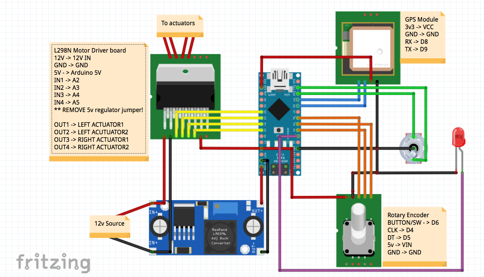 RED/BLACK = power/gnd, YELLOW = motor controller, BLUE = GPS, ORANGE = Rotary Encoder, GREEN = Surf switch, Purple = LED
- Do NOT try to drive your lenco actuators directly(!) You need to use marine relays to drive them (https://www.amazon.com/PACK-AMP-Waterproof-Relay-Harness/dp/B074FSZWVT/) you'll need 4 total.
- Wire your relays according to lenco diagrams (1 relay per direction/tab) and you'll toggle them with the motor driver in the arduino.
- Wire your actuators with enough power (a single 25A circuit to the back of the boat is fine.)
- This is not covered in detail here as it's well documented online already - and unrelated to this project!
- Since everything except the actuators is very low draw all wiring can be 18-22AWG
- REMOVE 5V REGULATOR JUMPER ON L298N. This is a small jumper by itself on the board.
- If you used the no-solder power supply above, just wire the in to your 12v power, out to the VIN pin and GND on your arduino.
- Wire power to the LM2596 "in" solder pads. Wire this to something that is not always powered or you'll kill your battery.
- Also solder a lead onto the LM2596 "in" solder pads to go directly to the L298N 12V in.
- Connect your LM2596 to a 12V source after turning the gold dial counter-clockwise 15-20 times. Use a multimeter to measure out pads until you get to 7-8V out.
- Solder wire on the LM2596 "out" solder pads to run to VIN/GND on arduino.
- Solder or connect 3v3 (+) and GND (-) to arduino pins.
- Connect RX/TX to pin D8/D9 on arduino
- Connect the 12v/GND to the raw power in (the source 12V not the ardiuno power.)
- Connect 5v to the arduino
- Connect the 4 IN1/IN2/IN3/IN4 to A2/A3/A4/A5
- Connect the OUT1 and OUT2 to the actuator relay at the back of the boat.
- Connect the OUT3 and OUT4 to the actuator relay at the back of the boat.
Wire each to:
- DT to D5
- CLK to D4
- ROTBUTTON to D6(Might be SWT/SWTCH on yours, its the open pin)
- 5V to the +
- GND shared between led/switch - wire to whichever you prefer
- LED + to D3 (I used a 12V LED but am feeding it 7v and its fine.)
- GND shared between encoder/switch - wire to whichever you prefer
- LEFT DEPLOY to D10
- RIGHT DEPLOY to D11
- GND (and GND for encoder/light)
- Install the arduino IDE and open the .ino sketch in the project.
- PLug in your USB cable to you arduino
- Select your board and port from the menu (nano/uno)
- Install the NeoGPS, EEROM and AltSoftSerial packages if they are not installed (Sketch -> Include library -> manage)
- Upload code to your arduino - there's no required code changes out of box.
- Open serial monitor and you should see it running - it will post a status update every second. If serial isnt working check the baud rate (9600) and the port.
You can easily test this before installing in your boat:
-
The code logs everything to the serial port when there are any changes - and full status updates once a second, so you can connect a USB cable and use the serial monitor to monitor in the arduino IDE in real time whats happening
-
Uncomment speedlimit=1; towards the end of the code by removing the leading // and upload the new code.
-
Plug your new power cables into a 12v source (IE: a wall wart with a screw adapter is super easy: https://www.amazon.com/inShareplus-Mounted-Switching-Connector-Adapter/dp/B01GD4ZQRS/ - otherwise just connect whatever 8-25v source you can.)
-
Connect a multimeter to the one of your actuator triggers (these are the wires that go to the actuator relays - out of the L298N motor controller.
-
Flip surf on that side you are using (if you dont get anything, try the other side.) You should see the multimeter read 12v/-12v or so depending on how you have it hooked up. This will only run for 3.5 seconds - so you might miss it if you aren't ready. If you used a different source voltage than 12v, you will see that on the multimeter instead, it is whatever you are feeding it.
-
Turn off the switch, you should see the reverse of above (-12/12)
-
Repeat for the other side
-
You have confirmed the actuator controls are all good now -- you can continue testing below if you want - otherwise dont forget to comment out the speedlimit=1; and reupload the code.
-
With one switch in surf mode and the multimeter connected to that side, turn your rotary encoder a bunch of clicks. You should see the multimeter trigger again within 1 second for whatever duration you chose.
-
Switch surf off and hold down the rotary button for 5-10 seconds and let go, you should see the multimeter again "retract" (it is retracting both at the same time, but you're only caputring the one the multimeter is connected to.)
-
Once you are happy with how everything is working, comment speedlimit=1; out again and upload the code. You are now ready to test on the water.
- Once on the water, switch surf to your preferred side and accelerate to atleast 8mph (editable at top of code.)
- The tab will deploy for 3.5 seconds by default (on opposite side, if you wired backwards, just fix at acutator wiring or update code.)
- To change the deploy time turn the dial counterclockwise to increase time, clockwise to decrease.
- Once you have found a good deploy time you can press the rotary button at anytime to save that as your new default setting
- If you have issues or a tab stuck deployed hold down the rotary button for 5 seconds and all tabs will retract fully (you'll need to switch back into surf mode probably.)
- If you have an issue and need to reboot hold down the rotary button for 15 seconds and let go, it will restart the arduino loop.
- If you used a small project box you can pull your arduino nano to reprogram it easily - or have a spare ready to swap in anytime.
- Make sure you dont feed 12-14V to your arduino or it will most likely die
- Wiring choices are up to you - you can use cat5 without issue and it makes it easy to wire jacks out of the control box. I dont recommend 8-10 conductor 18AWG wire as it is too bulky and stiff to be workable (from experience.)
- I use 4x4x2 electrical boxes with lids from homedepot for my projects - cheap, waterproof, somewhat tight for all these components - but they do all fit. Everything in box:

