Version 1.5 and up of KaRadio32 allows you to configure gpio's and two custom IR keys per action.
This allows you to take advantage of the standard software even if your port configuration and/or your remote control are not the same.
The configuration must be specified in a csv file.
A template is given by the pattern.csv file
The default configuration of the current software is in the standard_adb.csv file.
A csv file is interpreted by an utility to generate a bin file that must be flashed at address 0x3a2000 only one time per esp32
The quick setup is to download the Windows all-in-one toolchain & MSYS2 zip file from dl.espressif.com. See
- Unzip the zip file to C:\ (or some other location, but this guide assumes C:) and it will create an msys32 directory with a pre-prepared environment.
- Open a MSYS2 MINGW32 terminal window by running C:\msys32\mingw32.exe. Create a directory named "esp" that is a default location to develop ESP32 applications. To do so, run the following shell command: mkdir -p ~/esp
- Type : cd ~/esp to move the newly created directory. If there are no error messages you are done with this step.
- Type : git clone -b v3.1.2 --recursive https://github.com/espressif/esp-idf.git
- Create a new script file in C:/msys32/etc/profile.d/ directory. Name it export_idf_path.sh Identify the path to ESP-IDF directory. It is specific to your system configuration and may look something like C:\msys32\home"your-user-name"\esp\esp-idf Add this to the above created script file: export IDF_PATH="C:/msys32/home/"your-user-name/esp/esp-idf" Save the script file.
- Close MSYS2 window and open it again. Check if IDF_PATH is set, by typing: printenv IDF_PATH The path previously entered in the script file should be printed out.
- Type : pip install --upgrade setuptools
- Type : python -m pip install --upgrade pip
- Type : pip install future
- Type : pacman -S mingw-w64-i686-python2-cryptography
- Type : pip install cryptography
- Place the Ka-Radio32-master files in "your-user-name"/esp folder. Find it at https://github.com/karawin/Ka-Radio32
Second make sure you have an updated partitions.bin file.
Find it at "your-user-name"/esp/Ka-Radio32/tree/master/binaries
This file contains the system partitions:
$ make partition_table
Toolchain path: /opt/xtensa-esp32-elf/bin/xtensa-esp32-elf-gcc
Toolchain version: crosstool-ng-1.22.0-80-g6c4433a5
Compiler version: 5.2.0
Python requirements from C:/msys32/home/jp/esp/esp-idf/requirements.txt are satisfied.
Partition table binary generated. Contents:
*******************************************************************************
# Espressif ESP32 Partition Table
# Name, Type, SubType, Offset, Size, Flags
nvs,data,nvs,0x9000,16K,
otadata,data,ota,0xd000,8K,
phy_init,data,phy,0xf000,4K,
ota_0,app,ota_0,0x10000,1792K,
ota_1,app,ota_1,0x1d0000,1792K,
device,64,0,0x390000,4K,
stations,65,0,0x391000,64K,
device1,66,0,0x3a1000,4K,
hardware,data,nvs,0x3a2000,8K,
*******************************************************************************
Partition flashing command:
python /home/jp/esp/esp-idf/components/esptool_py/esptool/esptool.py --chip esp32 --port com5 --baud 460800 --before default_reset --after hard_reset write_flash 0x8000 /home/jp/esp/Ka-Radio32/build/partitions.bin
************************************************ *****************************
Compared to an old version, it adds the declaration of the partition "hardware" which interests us.
Rename the pattern.csv file with the name of your c
ard, for example lolin32.csv
Beware: not comment line or empty line allowed in a csv file.
The declaration of gpio's is a not so easy task.
Any error results in an incorrect start of the software.
If the software does not start properly, please check your values.
A common mistake is to declare the same number for two functions.
See the log on the serial interface.
Edit the csv file to enter your gpio and options definitions.
See gpio.h for the default values if missing in the csv file.
Only modify the lines beginning with L_ or P_ or O_ by modifying only the last number.
for example:
P_MISO, data,u8,19
Change 19 to the desired number.
Do this for all P_ and O_lines.
Never change the string "P_XXXX, data,u8,"
A value base 10 is mandatory for each P_.
- Free strings:
L_LABEL A free string for the name of the csv or other.
L_COMMENT A free string of your choice.
These strings can be viewed with the command sys.conf on serial or telnet.
Definition of the lines in csv
- SPI Bus:
K_SPI Select the used spi : 1: HSPI, 2: VSPI
P_MISO Master Input, Slave Output
P_MOSI Master Output, Slave Input Named Data or SDA or D1 for oled
P_CLK Master clock Named SCL or SCK or D0 for oled - VS1053B:
P_XCS XCS
P_RST RST
P_XDCS XDCS
P_DREQ P_DREQ - ENCODERS 0 & 1:
P_ENC0_A pin A clk
P_ENC0_B pin B Data
P_ENC0_BTN pin SW
P_ENC1_A pin A clk
P_ENC1_B pin B Data
P_ENC1_BTN pin SW - BUTTONS PANEL 0 & 1 of three buttons (switch to gnd):
P_BTN0_A click:start/stop, double click:toggle, held: station
P_BTN0_B click: +
P_BTN0_C click: -
P_BTN1_A click:start/stop, double click:toggle, held: volume
P_BTN1_B +
P_BTN1_C - - JOYSTICK 0 & 1
P_JOY_0 Volume control P_JOY_1 - Bus I2C (Oled & Lcd):
P_I2C_SCL SCL or SCK
P_I2C_SDA SDA
P_I2C_RST RST if any - LCD on SPI bus:
P_LCD_CS CS
P_LCD_A0 A0 or D/C or DC
P_LCD_RST RST or RES - Infrared remote:
P_IR_SIGNAL ir Y Signal - I2S bus:
P_I2S_LRCK LRCK
P_I2S_BCLK BCLK
P_I2S_DATA DATA - ADC keyboard:
P_ADC_KBD gpio32 to 39 or 255 if not used. - ADC Battery:
P_ADC_BAT gpio32 to 39 or 255 if not used. - LCD Backlight:
P_BACKLIGHT GPIO of the hardware device. - TOUCH SCREEN:
P_TOUCH_CS GPIO of the t_cs pin of the touch or 255 if no screen
Other pins are t_clk, t_din, t_do respectively the spi clk, mosi, miso. T_irq is not used. - LED GPIO
P_LED_GPIO GPIO of the status led - DEEP_SLEEP
P_SLEEP GPIO GPIO to enter Deep sleep if set to P_LEVEL_SLEEP
P_LEVEL_SLEEP logical level to be set on P_SLEEP GPIO to enter deep_sleep mode.
- LCD CONTROL
O_LCD_TYPE Type of lcd (see addon.h file).
O_LCD_ROTA Control the rotation of the LCD, 0 no rotation, 1: rotation.
O_LCD_OUT The tempo to light off the screen in seconds. 0 if no tempo. O_LCD_STOP The tempo to light off the screen on stop mode. 0 if no tempo
O_LCD_BLV The percent of the backlight if hardware wired. range 0 to 100. O_DDMM_FLAG The format of the date to display 0:MMDD, 1:DDMM. - Buttons option
O_BTN0 The active level of buttons: 0=LOW, 1:HIGH ( 0=Default)
O_BTN1 The active level of buttons: 0=LOW, 1:HIGH ( 0=Default) - Audio output
O_AUDIO The initial Audio mode: 0=I2S (Default), 1=MERUS, 2=DAC, 3=PDM, 4=VS1053
- GPIOs 34 to 39 are input only pins.
These pins don’t have internal pull-ups or pull-down resistors.
They can’t be used as outputs, so use these pins only as inputs or ADC usage. - Digital to Analog Converter (DAC)
There are 2 x 8 bits DAC channels on the ESP32 to convert digital signals into analog voltage signal outputs.
These are the DAC channels: - DAC1 (GPIO25)
- DAC2 (GPIO26)
K_SPI,data,u8,2
- 1 is the spi HSPI_HOST
- 2 is the spi VSPI_HOST (default)
The spi bus is initialized in any case. It used for the vs1053 and/or the LCD if needed.
Prefered gpio for the spi bus (IOMUX):
HSPI: SCLK=14, MISO=12, MOSI=13
VSPI: SCLK=18, MISO=19, MOSI=23
If MISO is not used , it can be ignored by a 255 value.
Two encoders maximum are supported, each with different actions:
Encoder0: the volume control and stations change when pushed and held,
Encoder1: the station control and volume change when pushed and held.
If P_ENC0_A = 255 the encoder (P_ENC0_A, P_ENC0_B, P_ENC0_BTN) is disabled (not used, the gpio's may be reused elsewhere).
If P_ENC1_A = 255 the encoder (P_ENC1_A, P_ENC1_B, P_ENC1_BTN) is disabled (not used, the gpio's may be reused elsewhere).
If If P_ENC0_A is not 255 and P_ENC0_BTN = 255, the push button is disabled.
If If P_ENC1_A is not 255 and P_ENC1_BTN = 255, the push button is disabled.
Two set of three buttons can be configured in place or with encoder(s). The only limit is the available gpio's.
Each set has functions equivalent to Encoder0 and Encoder1:
click on button A: Start/Stop playing
click on button B and C: volume down and up for set 0 (P_BTN0), Station down and up for set 1 (P_BTN1)
held on button A: click on button B and C: volume down and up for set 1 (P_BTN1), Station down and up for set 0 (P_BTN0)
A button may be active with a level of 0 volt (0) (default) or +3.3volt (1)
If a set is not used, P_BTNx_A must be set to 255. In this case P_BTNx_B P_BTNx_C are disabled too.
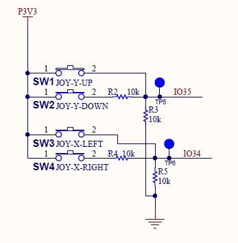
A joystick is a set of two buttons but both cannot be pushed at the same time.
The GPIO must be an ADC one, i.e gpio32 to 39 or 255 if not used.
Joystick 0 controls the volume,
Joystick 1 controls the station choice.
Botton 0 is 3.3 V
Button 1 is 3.3/2 V
An example of joystick:
If I2C is not used (ie no lcd or spi lcd) the gpio of the i2C can be reused elsewhere.
To formally disable I2C : P_I2C_SCL and/or P_I2C_SDA must be set to 255
I tried this DAC:
https://www.aliexpress.com/…/Interface-I2…/32849017570.html
To connect it do:
FLT GND
DMP GND
SCL Not connected
BCK is P_I2S_BCLK
DIN is P_I2S_DATA
LCK is P_I2S_LRCK
FMT GND
XMT 3.3V
VCC 5V or
3.3 3.3v
GND GND

If Vcc input is 5V, the 3.3V output the 3.3V but you can directly input the 3.3V here if the 5V is not available.
If not used P_XCS must be set to 255. Gpio of P_RST P_XDCS P_DREQ may be reused elsewhere.
If IR remote control is not used P_IR_SIGNAL must be set to 255
If the ADC keyboard is missing, set P_ADC to 255.
GPIO pin must be gpio32 to 39 or 255 if not used.
Compatible with https://github.com/karawin/Ka-Radio/blob/master/Hardware/controles.pdf and the one found at https://www.drive2.ru/b/487463808323813881/
The stop button is replaced with "Toggle Time/Infos" and "start replaced with "Start/Stop"
The ESP32 ADC can be sensitive to noise leading to large discrepancies in ADC readings. To minimize noise, users may connect a 0.1uF capacitor to the ADC input pad in use
If the ADC Battery hardware is missing, set P_BAT to 255 The hardware must be as follow: Gnd<---R1--- to P-BAT ---R2--->VBat with R1 = R2 >= 100000 ohms
If your B/W oled has an artefact on the left for type 0, change it to type 1 (command sys.lcd("1") or O_LCD_TYPE,data,u8,1
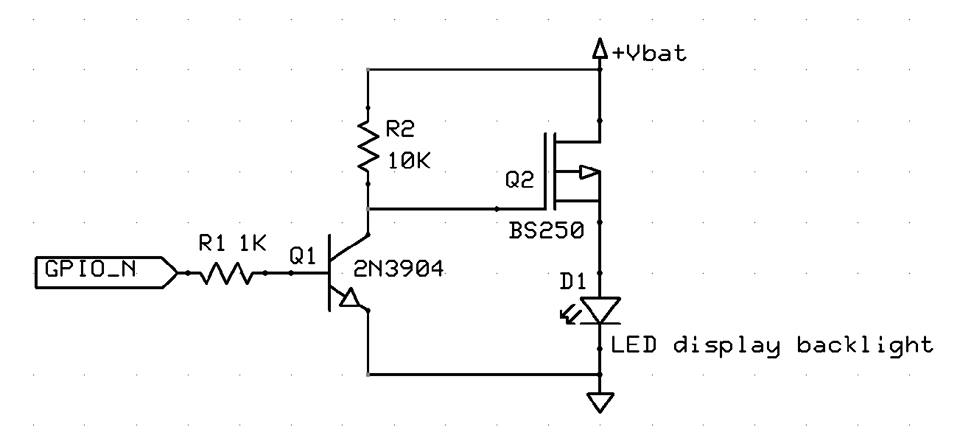
Thanks to Vadim Polyakovsky:
A small optional schematics update which allows to switch LCD backlight on and off in case of battery powered KaRadio. The switching off timeout in x sec could be defined by sys.lcdout("x") terminal command. The display and its' backlight will wake up automatically in case of new meta, encoder or IR event. This way the battery life on one charge will be extended. Obviously not needed for OLED displays and wall plug power socket operation. A software support is done by Jean-Pierre in the new custom.c file. A GPIO number could be chosen among not used ones and defined respectively. Enjoy!
Additionally, a backlight value from 0 to 100 can be choosen with the O_LCD_BLV or the sys.lcdblv command.
This external device turns off the LCD backlight in addition to the screen clear.
Usefull if a battery is used.
If the hardware device is missing, set it to 255
P_TOUCH_CS of the t_cs pin of the touch or 255 if no screen.
Other pins are t_clk, t_din, t_do respectively the spi clk, mosi, miso. T_irq is not used.
The screen must be calibrated with the command sys.cali[brate]
The screen is divided in 5 zones:
- Center: Start/Stop
- Top: Volume+
- Bottom: Volume-
- Left: Station-
- Bottom: Station+
If any options value is 255, the values defined by sys. command are unchanged.
If a sys. command changes the value in csv, the internal flashed bin of the csv is updated.
As long the original bin is not flashed again, the internal value apply.
Enter ESP32 Deep Sleep, and powerdown peripherals, when pin P_SLEEP GPIO is set to P_LEVEL_SLEEP.
( https://docs.espressif.com/projects/esp-idf/en/latest/esp32/api-reference/system/sleep_modes.html )
Wake up (EXT0) when P_SLEEP GPIO pin level is opposite to P_LEVEL_SLEEP.
Only GPIOs which have RTC functionality can be used: 0,2,4,12-15,25-27,32-39. And note that GPIO12 is a bootstrap pin, ESP32 might not even start up if GPIO12 is grounded.
If you use a remote control with different codes from the default ones, you can give your codes by key. Two codes per key are possible:
For example for the K_OK key
K_OK, data, string, 0xFF0040 0xFF0040
or
K_OK, data, string, 0xFF0040
if you only have one code per key.
or
K_OK, data, string,
if no code is given for the OK key
Never change "K_XXXX,data,string,"
Reminder: to see the code of a key on your remote control, change the log level to sys.logi
Press a key and see the log. You will see something like that:
I (1204396) addon: IR event: Channel: 0, ADDR: ff00, CMD: bf40 = FF0040, REPEAT: 0
Where FF0040 is the 0xFF0040 code needed.
The keys and actions are:
K_UP  		Change to next Station
K_LEFT		Volume Down -5
K_OK		Toggle play/Stop
K_RIGHT		Volume up +5
K_DOWN		Change to previous station
K_0			Enter number of the wanted station
K_1			Enter number of the wanted station
K_2			Enter number of the wanted station
K_3			Enter number of the wanted station
K_4			Enter number of the wanted station
K_5			Enter number of the wanted station
K_6			Enter number of the wanted station
K_7			Enter number of the wanted station
K_8			Enter number of the wanted station
K_9			Enter number of the wanted station
K_STAR		Play
K_DIESE		Stop
K_INFO		Toggle time/info display
No comment is allowed in this csv file.
Save the csv file.
Some samples are in the boards directory.
-
Place the Ka-Radio32-master files in "your-user-name"/esp folder
-
Place your modified csv file in the Ka-Radio32-master/boards folder
-
Return to the msys32 window and navigate to the Ka-Radio32-master/boards folder
-
Start the command : ./nvs_partition_generator.sh yourname[.csv] to generate build/yourname.bin
Result :
MINGW32 ~/esp/Ka-Radio32-master/boards
$ ./nvs_partition_generator.sh modified_adb
python ./nvs_partition_gen.py modified_adb.csv build/modified_adb.bin 0x2000
done
With ESP DOWNLOAD TOOL
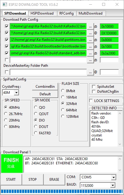
or esptool.py command at address 0x3a2000
It seems that there is a problem with this ESP DOWNLOAD TOOL for flashing the bin alone.
In case of problem, flash it with another bin (bootloader.bin or KaRadio32.bin)
This binary is to flash one time and on each modification of the csv.
Now you can enjoy the standart OTA. No needs to generate your own KaRadio32.bin.
JP 2018