Available at: https://keyhive.xyz/shop/lily58
| Part | Qty | Description |
|---|---|---|
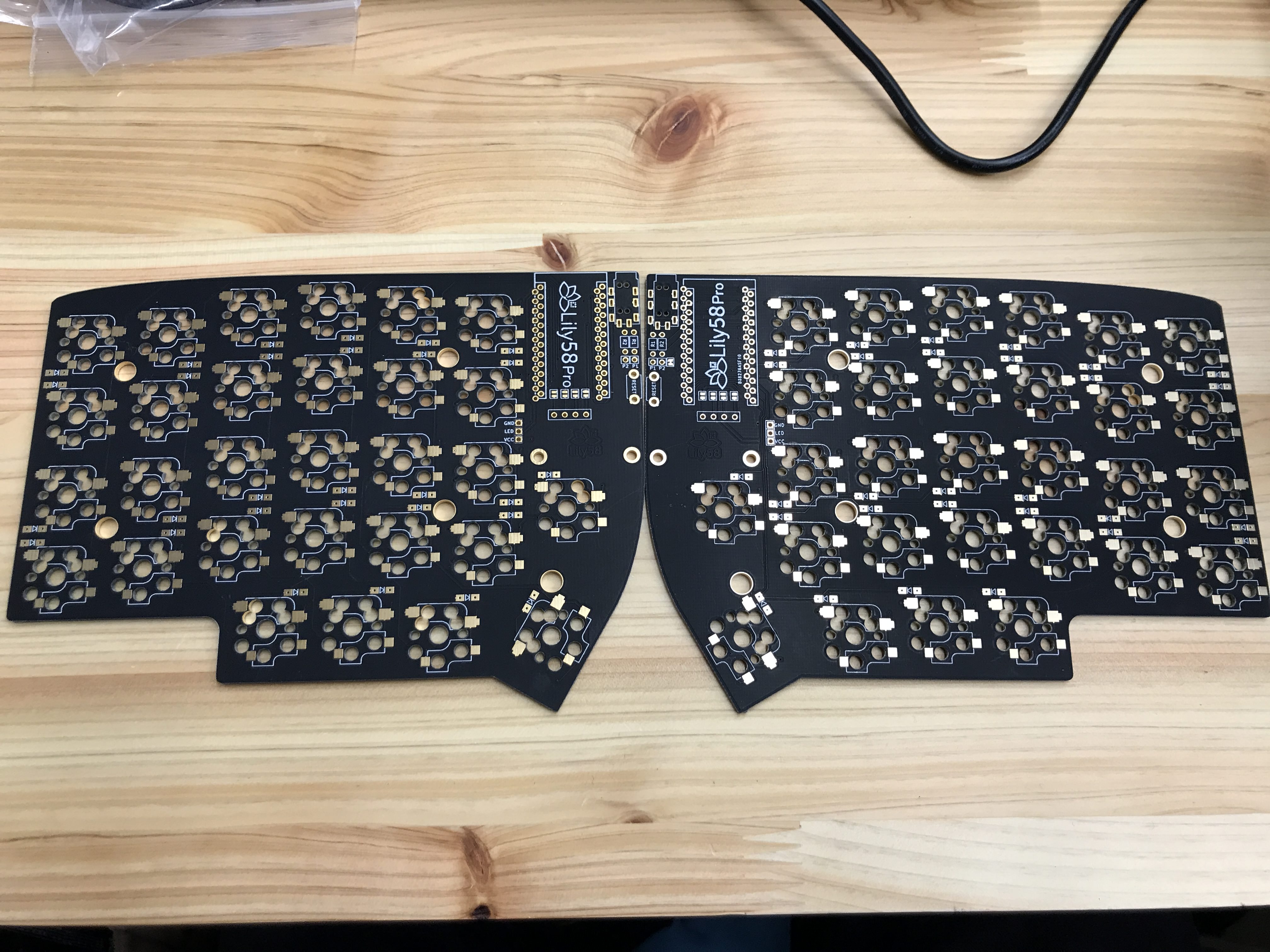
| Lily 58 PCB | 2 | PCBs are reversible |
| Lily 58 plates | 1 | 2 switch plates, 2 bottom plates |
| Pro micro | 2 | |
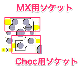
| Switches | 58 | Either MX or choc switch |
| Kailh hot swap socket | 58 | |
| Diodes 1N4148W | 58 | throughhole diodes are not recommended due to a footprint error |
| Tactile switch | 2 | 6x3x2 right angle tactile switch |
| TRRS jacks | 2 | |
| M2 Standoffs | 10 | Choc: 4 mm, MX: 7 mm. Also known as spacers |
| M2 screw | 28 | 6mm is ideal |
| TRRS cable | 1 | Cable for 3.5 mm audio, also called AUX cable (4-pole cable recommended) |
| Micro USB Cable | 1 | |
| OLED module | 2 | |
| Keycaps | 58 | 56 1u keys, 2 1.5u keys for the thumb keys |
- Solder
- Flash controller
- Solder controller
- Solder the reset button
- Test the keyboard
- Solder OLEDs
- Solder TRRS jacks
- Install OLED cover
- Install switches
Soldering diodes is relatively straightforward. Refer to Soldering diodes if you need further guidance.
Refer to Soldering Kailh hot swap sockets if you need further guidance.
Flash the controller (pro micro, Elite C, nice!nano, etc) with the firmware. This ensures that the controller works completely before soldering it permanently to the board.
The default lily58 keymap does not have LEDs enabled so if you plan on having LEDs this would be the time to modify the firmware to enable it.
Refer to Soldering the controller if you need further guidance.
Insert into holes. Solder in place on the bottom side of the pcb.
At this point it should function as a keyboard. When you plug it in, the on-board LEDs should turn on. Insert a switch into a hot swap socket and test that a keycode is pressed. You might consider testing every key in case there are problems with the diodes or hot swap sockets.
After this, solder remaining components.
If you've socketed the controller, also consider socketing the OLEDs else the controller will be trapped underneath it.
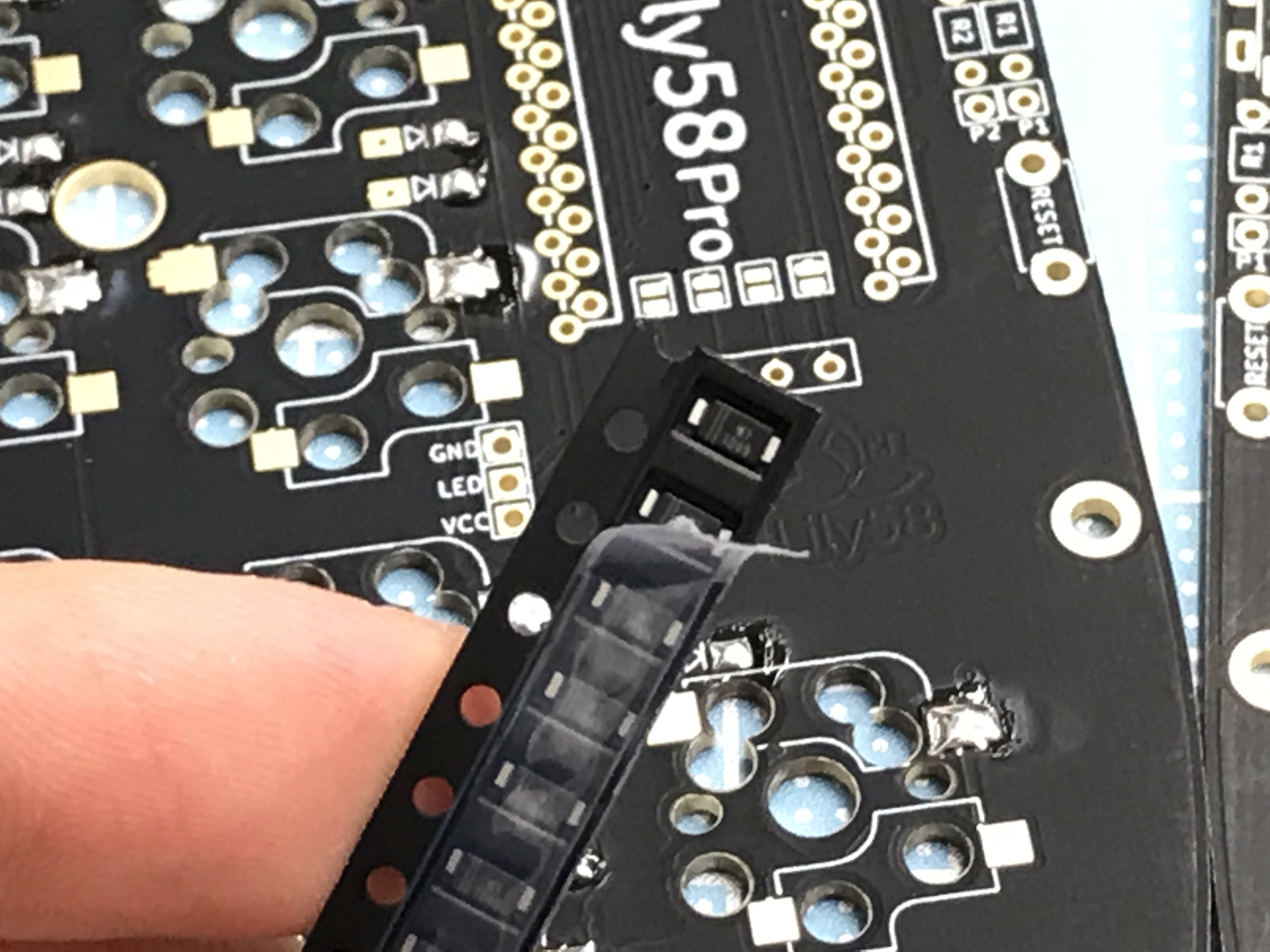
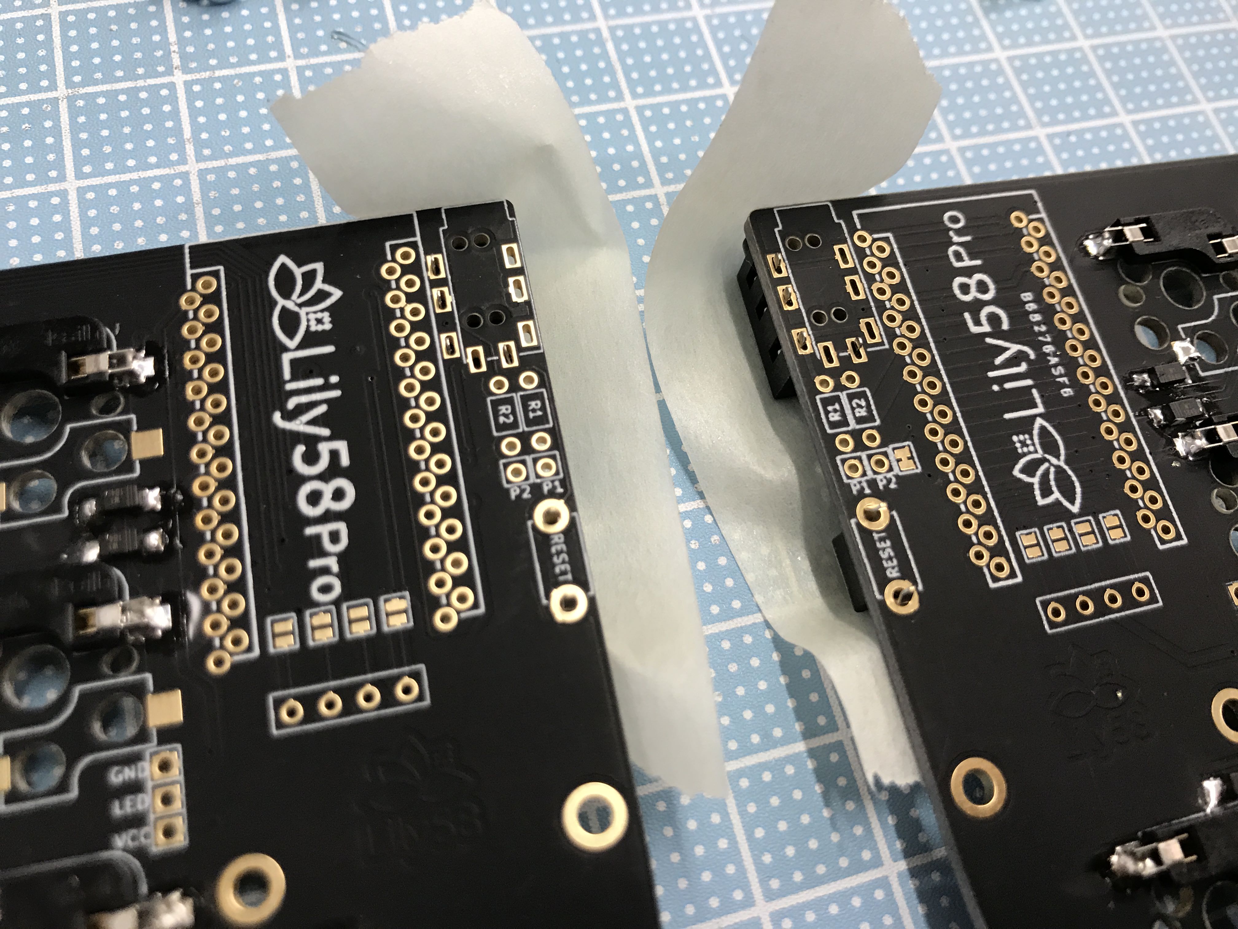
Solder the 4 jumper pads on the same side that the pro micro will be mounted on. DO NOT FORGET THESE; they will be very difficult to access after the pro micro is soldered into place.
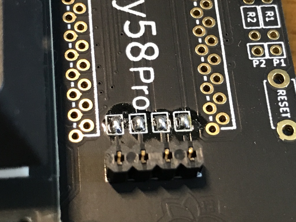
Insert headers into holes. Use electrical tape to secure in place while you solder the holes on the bottom side of the PCB.
⚠︎ The OLED is not required but if you omit it, you must disable it in the firmware. If you do not, you will experience "jittery" keystrokes as if some keys were lost while in transit. Disabling it in the firmware will fix this behavior.
Insert into holes. Solder in place on the bottom side of the pcb
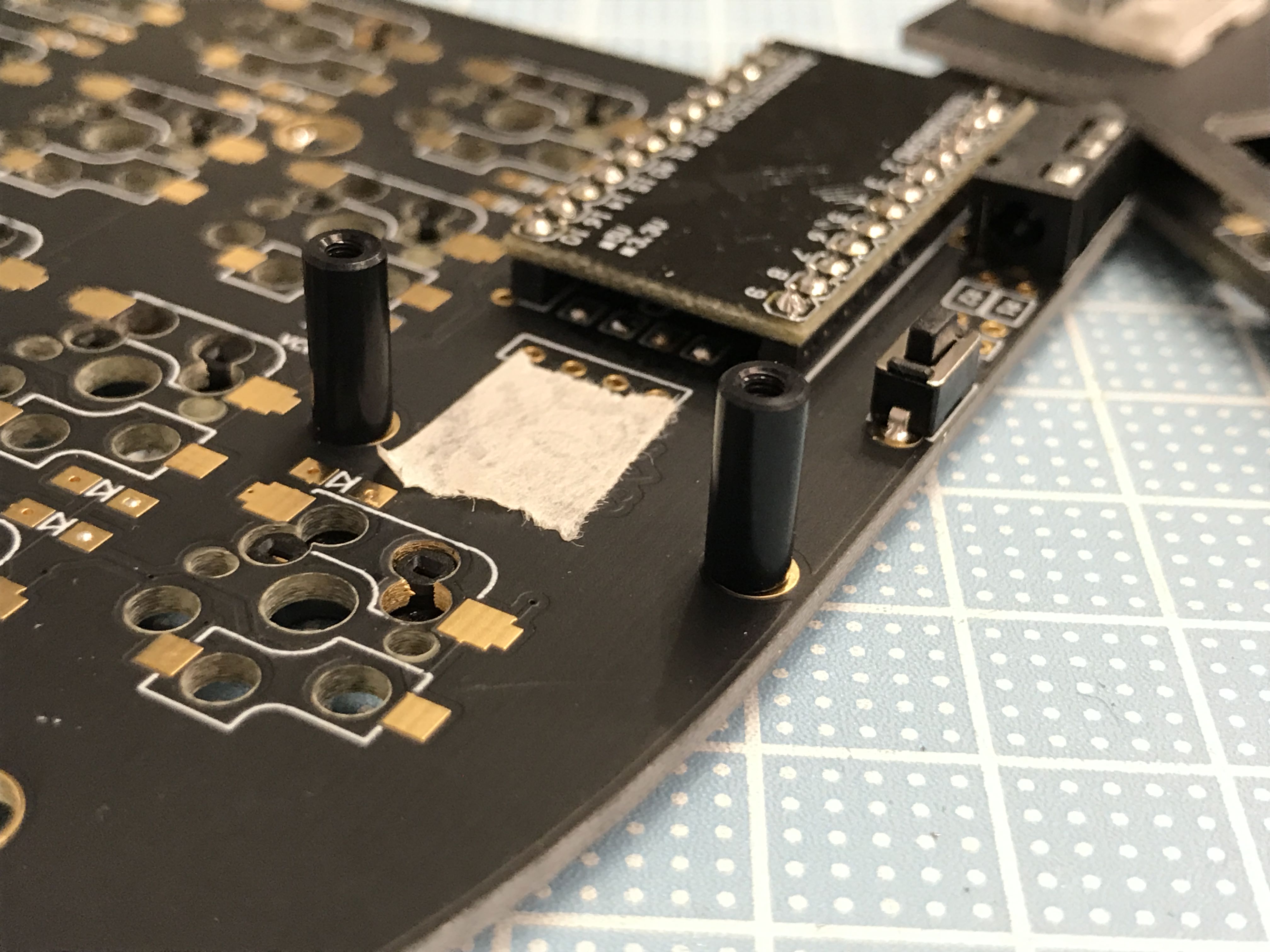
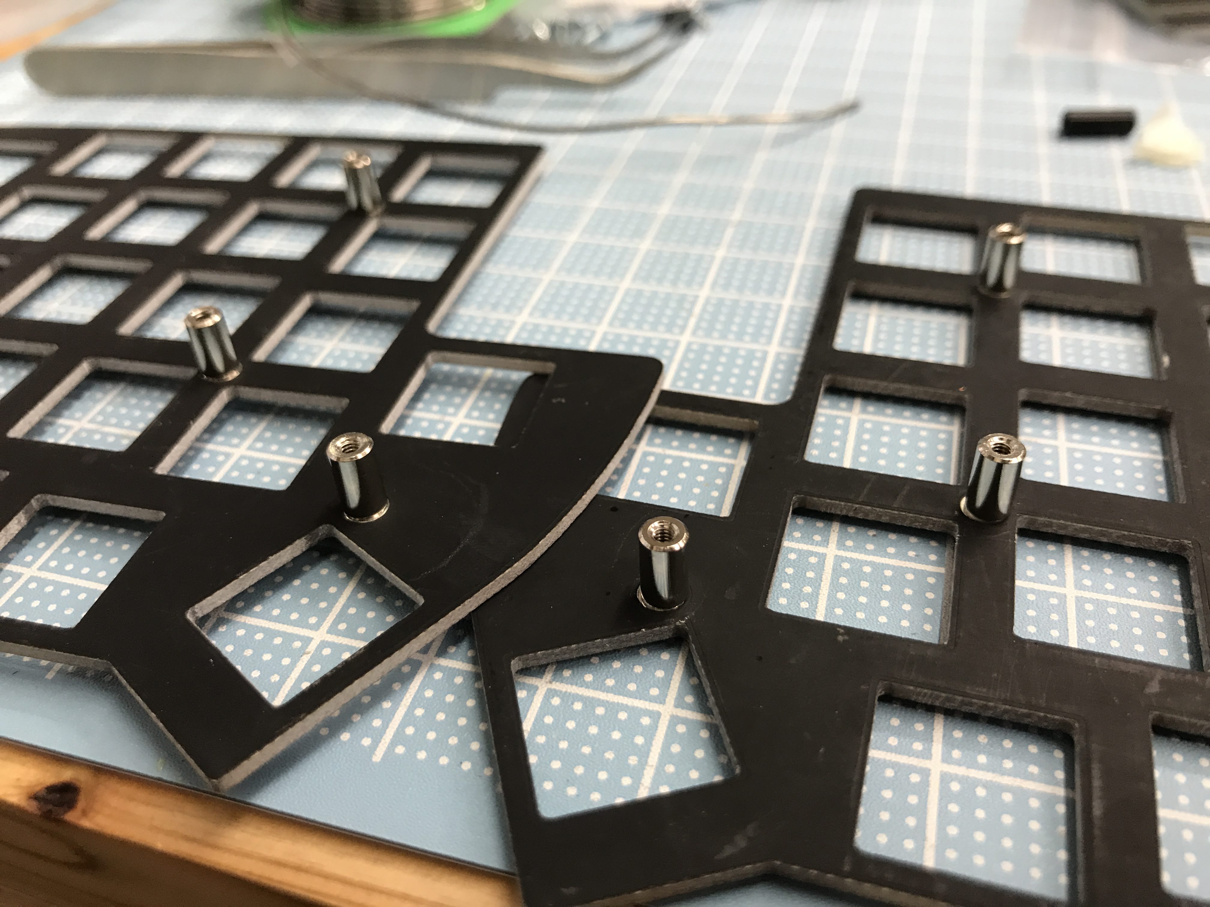
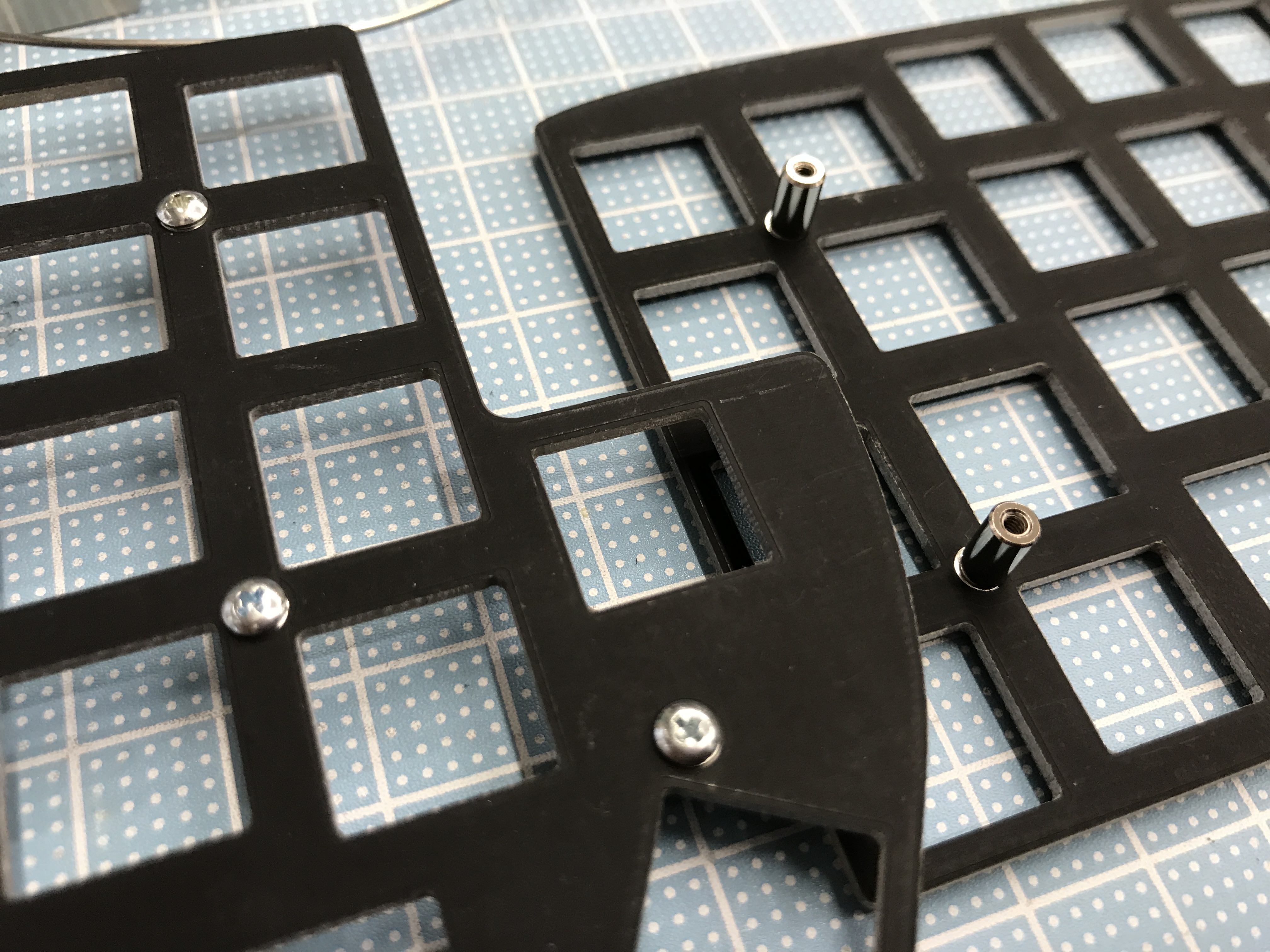
Install the 4 spacers into the holes just below the pro micro, screw from the bottom.
Install the standoffs onto the switch plates.
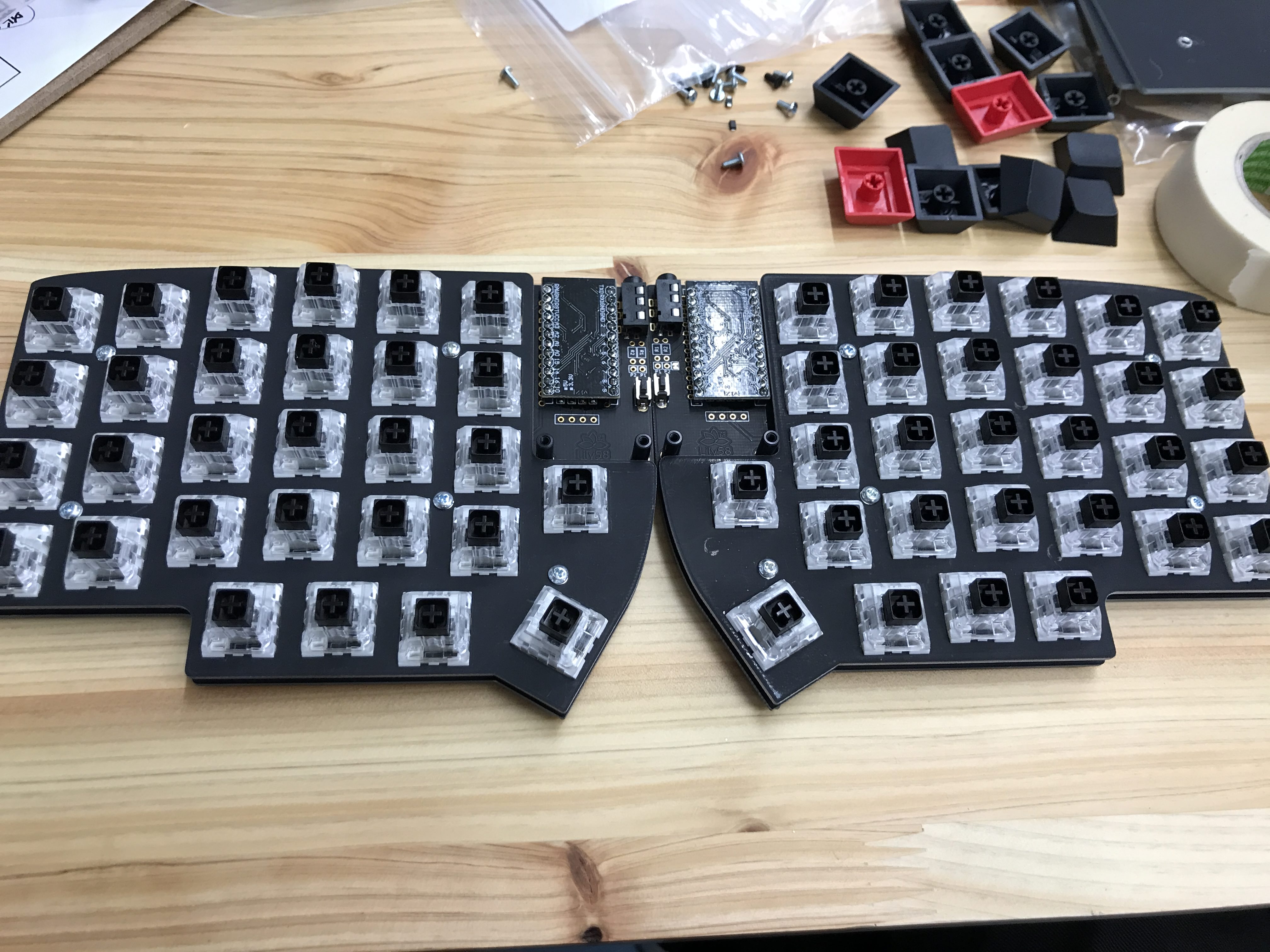
Insert switches into the plate. Begin by placing one on each of the corners of the PCB to give you some stability. Be cautious of bent pins when pushing the switch down. Kailh Box and choc switches require a bit of force for installation.