- many environmental and air quality sensors can be used concurrently
- Integration in Sensor.Community (formerly Luftdaten.Info)
- Configuration via HTTP in local WiFi or with a Sensor-as Access-Point
- Support for OLED- and LCD-Displays (SSD1306, SH1106 and LCD1602, LCD2004)
- Wide selection of API integrations for measurement reporting
- Ability to print measurements as CSV via USB-serial
- Used with ESP8266 (NodeMCU v2/v3 and compatible) and ESP32 (experimental)
Please refer to Contributing README for details.
For German Version see: Konfiguration der Sensoren
If a (previously) configured WiFi is not reachable within 20 seconds after power-on,
the firmware flips itself into AP mode and creates a WiFi network in the form airRohr-\[Sensor-ID\].
This WiFi network is by default unencrypted. When a client connects to this, it will get
redirected to the sensors web server http://192.168.4.1/ which allows initial configuration.
Configurable is
- WiFi Access Point to use
- Options for measurements (Sensors to poll, intervals..)
- APIs to send the measurements
The unencrypted Access Point for initial configuration will turn itself off after about 10 minutes. In order to reactivate please power cycle the board.
The DHT22 sensor is originally an Indoor sensor. For outdoor use it appears to be rather sensitive to water condensation after 100% rel.Humidity that keep it for very long time (sometimes forever) at 99.9% value. Also it appears to be sensitive to high UV light, which tends to cause the sensor to crash until hard power-loss restarted.
Better experiences have been made with a BME280 or SHT3x sensor, so consider those instead.
Connecting/Powering via a computer USB will provide USB serial with the settings 9600 baud 8N1. By default the sensor will provide human readable debug information of configurable granularity there.
All measurements can also be read as CSV via USB-Serial when using the USB port in the settings 9600 Baud 8N1. In order to avoid interfering of debug options (see earlier section) set debug to None in the configuration.
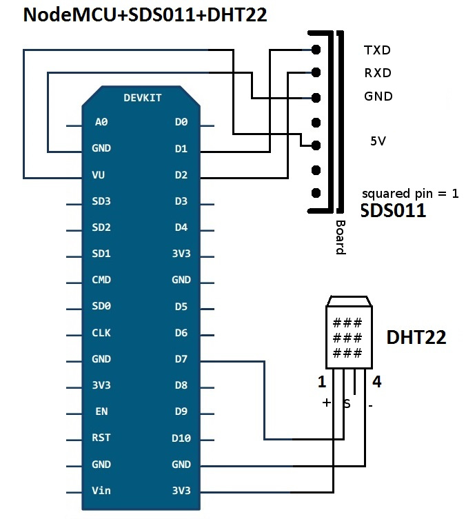
Please refer to the Pinout of NodeMCU v2 and v3 for much more detailed information about the individual pin functions.
Note: Serial connections are always crossed (RX on one side is connected with TX on other side)
- Pin 1 (TX) -> (RX) Pin D1 (GPIO5)
- Pin 2 (RX) -> (TX) Pin D2 (GPIO4)
- Pin 3 (GND) -> GND
- Pin 4 (2.5m) -> unused
- Pin 5 (5V) -> VU
- Pin 6 (1m) -> unused
- Pin 1 => 3V3
- Pin 2 => Pin D7 (GPIO13)
- Pin 3 => unused
- Pin 4 => GND
Please check your version (pinout) at [https://datasheets.maximintegrated.com/en/ds/DS18B20.pdf] Uses the same PIN D7 as DHT22, so DHT22 OR DS18B20 can be used.
- GND -> Pin GND
- DQ -> Pin D7 (GPIO 13)
- VCC -> Pin 3V3 or Pin VU
Pinout: 8 7 6 5 4 3 2 1
- Pin 1 (VCC) -> VU
- Pin 2 (GND) -> GND
- Pin 3 (SET) -> unused
- Pin 4 (RX) -> Pin D2 (GPIO4)
- Pin 5 (TX) -> Pin D1 (GPIO5)
- Pin 6 (RESET) -> unused
- Pin 7 (NC) -> unused
- Pin 8 (NC) -> unused
Pinout PMS7003: 9 7 5 3 1 10 8 6 4 2
- Pin 1/2 (VCC) -> VU
- Pin 3/4 (GND) -> GND
- Pin 5 (RESET) -> unused
- Pin 6 (NC) -> unused
- Pin 7 (RX) -> Pin D2 (GPIO4)
- Pin 8 (NC) -> unused
- Pin 9 (TX) -> Pin D1 (GPIO5)
- Pin 10 (SET) -> unused
Pinout: 8 7 6 5 4 3 2 1
- Pin 1 (3.3V) -> unused
- Pin 2 (5V) -> VU
- Pin 3 (NC) -> unused
- Pin 4 (NC) -> unused
- Pin 5 TEST) -> unused
- Pin 6 (TX) -> Pin D1 (GPIO5)
- Pin 7 (RX) -> Pin D2 (GPIO4)
- Pin 8 (GND) -> GND
- VCC -> Pin 3V3
- GND -> Pin GND
- SCL -> Pin D4 (GPIO2)
- SDA -> Pin D3 (GPIO0)
Pinout: 1 2 3 4 5
- Pin 1 (5V) -> Pin VU/VIN
- Pin 2 (SDA) -> Pin D3 (GPIO0)
- Pin 3 (SCL) -> Pin D4 (GPIO2)
- Pin 4 (SEL) -> Pin GND
- Pin 5 (GND) -> Pin GND
- VCC -> Pin VU
- GND -> Pin GND
- SCL -> Pin D4 (GPIO2)
- SDA -> Pin D3 (GPIO0)
- VCC -> Pin VU
- GND -> Pin GND
- SCL -> Pin D4 (GPIO2)
- SDA -> Pin D3 (GPIO0)
VCC and GND can be provided by board (use 3.3v!)
Note: Serial connections are always crossed (RX on one side is connected with TX on other side)
- TX von Neo -> Pin D5 (RX)
- RX von Neo -> Pin D6 (TX)
For use of multiple sensors with Sensor.Community (formerly Luftdaten.info), you need to specify a virtual API Pin in the sensor registration form at devices.sensor.community. The firmware uses the following API pins hardcoded. These match what the Sensor.Community API expect and will be used by default when selecting the correct sensor model.
- HPM/PMS/SDS011/SPS30 => Pin 1
- BME280 => Pin 11
- BMP180/BMP280 => Pin 3
- DHT22/HTU21D/SHT3x => Pin 7
- GPS(Neo-6M) => Pin 9
- DS18B20 => Pin 13
- DNMS +> Pin 15