Any chance this will work with a HD-VC9900 #165
Comments
|
Well I ve read that this should work, but you would need an extra adapter to inject the audio into the hdmi signal. |
|
I can confirm that it works fine. |
|
Is the instructions for this the same as with a GBS8200 including the clock generator? The chips look like they are in the same location. So all wires to the same pins on the same chips for both boards? |
|
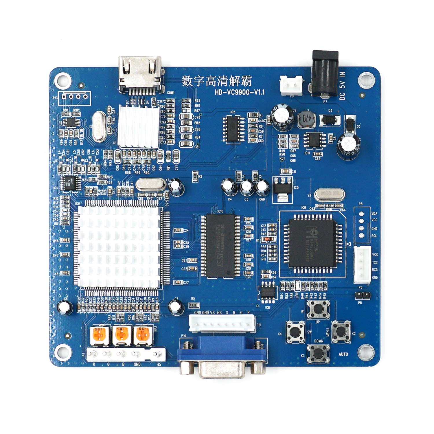
Using this image as reference I can tell you that:
As for the audio input I could not find a picture where the heatsink on the HDMI chip has been removed, so I can only speculate that audio injection might be possible depending on which IC they have used. If you can send pictures of it (and maybe the IC left of it) I can have a look, still best-case scenario you will have to solder a couple of wires onto tiny legs, which might be tricky. |
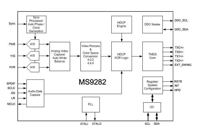
I have just bought one and removed and scraped off the IC, the device is a MS9282 by MACRO SILICON, according to the tiny bit of information I have it is capable of audio input, but I cannot find any information on the chips pinout or a datasheet. Anybody got any ideas? I have seen a company selling this board with an addon board that seems to allow audio as well so it must be possible https://gamescare.com.br/produto/gbs-control-digital-gamescare-scaller-1080p-hdmi-nativo/ |
|
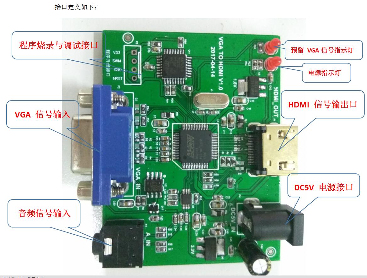
Given that there is no available datasheet, I've looked at some reference photos I am quite curious of the chip right below P13 on the upper left corner (according to the reference image), could you check the markings if it has any? P13 looks awfully like a 4-pin jack connector, maybe they copy-pasted the ADC on the pcb as well. If that's not the case the only option is to add a daughter board with the I2S ADC and solder some fine wires to the feet of the MS9282 chip. (If this is the case I am very skeptical that the pre-assembled board has audio) |
|
@mrjackv Yes I was curious about P13 as well can find no reference to its use anywhere on the net, the 4 pin connector only appears to have 3 tracks connected to that small chip next to it via a couple of resistors, looked suspiciously like it could be an unused audio jack port possibly as it has the right amount of pins technically. I tried to look for that small chips datasheet a few days ago before I posted but had no luck, the markings on the chip are R16A L27LN again could not find any sort of datasheet as to what it is. I noticed the the MS9282 in the block diagram has SPDIF, I wondered if you could interface an SPDIF capable device in over this directly? My use for this board was that I was hoping to retrofit it into a PHAT PS2 to give it native HDMI basically so I know it has an SPDIF. Looking at reference photo 1, it has 4 pins leading to that small chip from there each audio pin off that small chip goes to a resistor and a capacitor. This is EXACTLY the layout of this chip, the only difference is that the pin location is the opposite side to the chip in the picture to where the audio connections are going, but is this definitely the same chip? There seems to be multiple models in that range so maybe it is similar, but not identical and maybe that difference changes the pin layout. There is also a diode that connects to pin 1 of that chip that is missing, I assume it will likely need this installing as well to activate it although it doesn't exist in photo 1 compared to this board. |
|
Audio is no problem. Already soldered it when i used the VC9900 to connect an old sega master system II to a new oled with hdmi only. I also have some pics of that. As the sega outputs an analog audio signal an the ms 9282 only accepts digital inputs, you need an adc converter. |
|
ADC converter: Desoldered in and out jacks.
Desoldered 2 pulldown resistors R66 R67 and connected 4 wires to ADC board. red = MCLK Masterclock Set the jumper in MASTER position. Tried slave first as i thought MS9282 is master, but it's other way round.
|


|
@Vitalic66 Wow thanks for sharing the solution. PCM1802 Datasheat: https://www.ti.com/lit/ds/symlink/pcm1808.pdf |
|
@jamesoft145 PCM1808 works fine for me:
|
|
As mentioned before, any i2s2 adc converter will work if you connect the 4 pins right. It is also important to look for the right masterclock, as it comes with 24576 mhz. The pcm1808 e.g. supports this clock. |
|
Just a heads up, I fitted my HD-VC9900 with a PCM1808 board that you can find for cheap on aliexpress, and it worked a treat. Only annoyance was the heatsink was larger than on Vitalic66 pic so I had to remove it and reattach it later with thermal double sided tape. |
|
hey, |
|
@LawnMo yes, you can wire like 82x0. Just need 75 ohm and 200 ohm (*3) for getting YPbPr input |
Thanks for the fast reply, I really appreciate it, do you know by any chance how/where I should hook YPbPr to ? I couldn't find good enough pics to look up where the traces go ^^ (any help appreciated as I'm not that savvy in electronics, as soon as I finish mine, I'll try to get this HD-VC9900 variant added to the wiki or write a dedicated tutorial for it, passing on the knowledge for others to build this ;) ) edit: nevermind, after a friend pointed at the datasheet, it seems like the 7525 just sort what signals it gets on the same pins, so RGBS is fine, no need to solder to any pins (thanks for the resistors values tho 👍 ) |
|
Could you post a picture how you wired op you're pcm1808? I tried this mod on mine, but now I have no HDMI output at all anymore! |
this is how I tested it prior to cleaner install |

|
@Ryoandr |
|
So it's the middle pin of the regulator? |
|
@Ryoandr yes |
no, this is the 1.8v regulator. There's 3.3v on pin 3 comming from the DC-DC buck. |
|
@Ryoandr you're right, I didn't see it was 1.8V 👍 |
|
@Ryoandr it's hard to tell on your picture but it looks like you didn't remove R66 and R67 ? Is that optional ? |
|
I did remove them, it's just some residual solder that makes it look like caps still on |
|
Tried to move the ground and the 3.3v supply, but no luck. I think I fried the HDMI output chip :( |
|
Only I seem to have some issues with c-sync. But the audio works fine now over HDMI. |

|
So what are the upsides/downsides of this VC9900 vs GBS8800? If I want just RGB SCART > HDMI (no need for sound) is this the simplest way to go? |
|
Hello all, |
|
Forewarning because I'm a dumdum who knows next to nothing about electronic engineering, so if anything I did is a bad idea, pls lemme know. I'm trying to clean up connections for both the esp8266 and the 1808. I reused 2 empty spots for pin connectors, so I could make them plug and play. For the esp8266 I removed R45 as it only seemed to connect the 2 unused vcc pins, then I made a quick jumper from the pin on IC6 to the other end of the resistor pad (I'm out of 28awg, so I managed with 26 lol). That way I can use all 4 pins on that connector for the 8266. Only other wire needed is 5v, and that's already on its own connector. For the 1808, I was I'm not a big fan of wires dangling from resistor pads, so I wanted something a little more substantial. I made use of the unused 4 pin connector spot on the top left of the board. The first pin is 3v3, third is GND. 2 and 4 are from the nearby IC, and there was no easy way to isolate those pins, short of cutting traces. I took a 6 pin connector, pried out pins 2, 4, 5, and 6. replaced them with right angle pins that I bend inwards a little bit, pressed them in with my iron, so they would be a little more flush. I taped off pins 2 and 4 on the board, so they wouldn't bridge, then soldered in 1 and 3. It's still not 100 sturdy, but infinitely better than it was. I'm planning on making a PCB design that I'll mount above with standoffs. I want it to hold the 8266, 1808, Si5351 clock, YPbPr inputs, LR audio inputs, and maybe scart, just cause. I've never done any PCB design before, so I've mostly been floundering. If I add Scart, would I need to put in a switch to change audio sources from RCA to Scart? I know its typically better to keep digital separate from analog, so for the 1808, just keep one side away from the rest? I'd also be sharing the SDA, and SCL lines between the esp8266 and the Si5351 clock, I have no idea what's digital and what's analog, also if it even matters with that. Also with grounding, I would assume all would be fine, but in my experience with guitars, I know ground loops are a thing to avoid, with that, should I only have 1 ground connection from the 9900 to my pcb, cause each pin connector has a ground that I can run up to the pcb. In addition, each of the chips I'll be mounting have multiple grounds, good/bad to connect all? |


|
Here is a good instruction on how to add component to a vc9900 it's in Japanese put its readable trough translate. Going to try this on my vc9900. |
|
Hello everyone, I was wondering if there was a noticeable improvement in picture quality between the VC9900 and the classic GBS boards. I’m new to all of this and I couldn’t find a lot of information about the VC9900 online. I would like to use this scaler to plug a GameCube (SCART) to a projector (1080p) that has both VGA and HDMI inputs. Thanks! |
|
@Miocastoor litteraly the same chips, only this has the vga->hdmi converter integrated instead of an additional extension at the back of a "regular" gbs-c. |
|
@LawnMo Thank you, that’s what I was wondering. |
Question for you; I am running same set up, Hooked up like you did. I couldn't see that well through the acrylic in the photo and removed the resistor at R65. Would this cause no sound? Also, I noticed that you had your audio inputs to the L and R input but no audio ground. I am running mono sound from a JROK pcb and Hooked up to R in and GND accordingly. Maybe this is my issue? Another thing maybe worth noting is that I get 4.94v at the main dc in but after the D2 resistor I get 4.51, is this not enough to power the 1808?
|

|
I figured it out. Here is a cleaner write up for the integration of audio using the pcm1808 with the vc9900. 1808 - VC9900 - Position (hdmi port towards you) |
|
Hello everyone. |
Dear sirs,
Is there any chance to get this working with a HD-VC9900. This device appears much like a GBS device only it outputs directly to HDMI.
The text was updated successfully, but these errors were encountered: