This document explains demo and how to run them.
The following table indicates the character of demos.
| Demo Name | Based AWS IoT contents | Description |
|---|---|---|
| PubSub | coreMQTT demos | It demonstrates simple MQTT communication between device and AWS server. |
| Fleet Provisioning | AWS IoT fleet provisioning | It provides the some secure provisioning operation to device at first connection to AWS server. |
| OTA | OTA tutorial | It provides the steps to update the firmware on your device. |
Each demo is independent as a FreeRTOS's task. It means multiple demos can be run at the same time.
The demos connect to AWS IoT core via the Ethernet, Cellular, or Wi-Fi with MQTT protocol by using the CoreMQTT-Agent library to share a single MQTT connection among multiple tasks.These tasks establish a server and client-authenticated TLS connection, and demonstrates the subscribe-publish workflow of MQTT.
This chapter explains step by step instructions for running demos by importing projects into e2 studio.
When you create as a new projects according to the FAQ below, you can skip step1 and step3.
https://en-support.renesas.com/knowledgeBase/21115016
- CK-RX65N
- RYZ014A as Cellular (CAT M1) module if you use Cellular communication
- DA16600 as Wi-Fi module if you use Wi-Fi communication
- IDE: e2 studio 2023-07 or later
- A user account of Renesas is required to download.
- Compiler: CC-RX V3.05.00 or later
- Code generator: RX Smart Configurator
- It is installed with e2 studio.
- Serial terminal application: such as Tera Term.
At first step, prepare this product on your local environment. Clone this repository by the following commands.
For long path name:
git config --global core.longpaths true
To clone using HTTPS:
git clone https://github.com/renesas/iot-reference-rx.git --recurse-submodules
Using SSH:
git clone git@github.com:renesas/iot-reference-rx --recurse-submodules
If you have downloaded the repo without using the --recurse-submodules argument, you should run:
git submodule update --init --recursive
Connect a RYZ014A with LTE antenna and SIM card to device board.
- Connect the LTE antenna to the RYZ014A. The antenna is packaged with the purchase of RYZ014A.
- The SIM card is required to be activated in advance (refer to your SIM card's guide), then insert it to the RYZ014A.
- Connect the RYZ014A to device board. In case of CK-RX65N, connected to the PMOD1 of it.
- Connect a USB cable to the RYZ014A for supplemental power supply.
Note:
- Depending on the country you live in or provider of SIM card, you may not use RYZ014A due to the supported bands. Refer to manual of RYZ014A about supported bands for details.
Also see Settings of Bands for band settings.
Connect a DA16600 to device board.
- Connect the DA16600 to device board. In case of CK-RX65N, connected to the PMOD1 of it.
Note:
- Depending on the country you live in, you may not use DA16600 due to wrong country code or timezone.
Refer to Settings of Country code and GMT timezone for settings.
Connect between device board and router/switch.
- Connect an internet-connected Ethernet cable to the Ethernet port attached on device board.
For more details, refer to the manual of CK-RX65N.
-
Set up jumpers of device board as follows:
- J2 Short for invalidating MCU current measurement point
- J11 Open for single-chip mode as MCU boot option
- J16 1-2 Short for debugging
-
For power supply and debugging, connect an USB cable between the debug connector (J14) on the CK-RX65N and your PC with installed e2 studio. This connector has a role of both of power supply and debugging.
-
For receiving debug logs, connect an USB cable between the USB-serial connector (J10) on the CK-RX65N and your PC with serial terminal application to receive logs. Note that debug logs mean serial output data which is coded in the demo program and Renesas driver software. It is not directly related to debugging on e2 studio.
Board settings image for cellular :
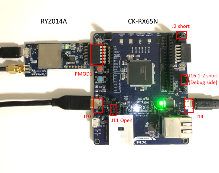
Board settings image for Wi-Fi :

Board settings image for ether :

Import demo projects into IDE; e2 studio.
-
Open e2 studio.
-
Choose workspace and click Launch.
-
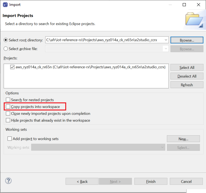
File -> Import... -> Existing Projects into WorkSpace.
-
Click Browse... and choose aws_ryz014a_ck_rx65n (for Cellular), aws_da16600_ck_rx65n (for Wi-Fi) or aws_ether_ck_rx65n (for Ethernet) demo.

Note: Ensure that copy projects into workspace is not selected.
-
Click Finish to import the projects.
Choose the following chapter according to using demo.
The <project_name> term means one of the following folder name according to used communication way:
| RX MCU and Board | Connectivity | Project name | Boot loader |
|---|---|---|---|
| CK-RX65N v1 | Ethernet | aws_ether_ck_rx65n | boot_loader_ck_rx65n |
| CK-RX65N v1 | Cellular(CAT M1) RYZ014A | aws_ryz014a_ck_rx65n | boot_loader_ck_rx65n |
| CK-RX65N v2 | Wi-Fi DA16600 | aws_da16600_ck_rx65n | boot_loader_ck_rx65n_v2 |
The following are combinations of demos that can be tried for each procedure.
| Operating Procedure | PubSub | Fleet Provisioning | OTA |
|---|---|---|---|
| Step 4-1: Run PubSub demo | ✓ | - | - |
| Step 4-2: Run PubSub demo with Fleet Provisioning | ✓ | ✓ | - |
| Step 4-3: Run Pubsub demo with OTA | ✓ | - | ✓ |
See this chapter when running PubSub demo.
Configure settings to run PubSub demo.
Configure settings to select combination of demos.
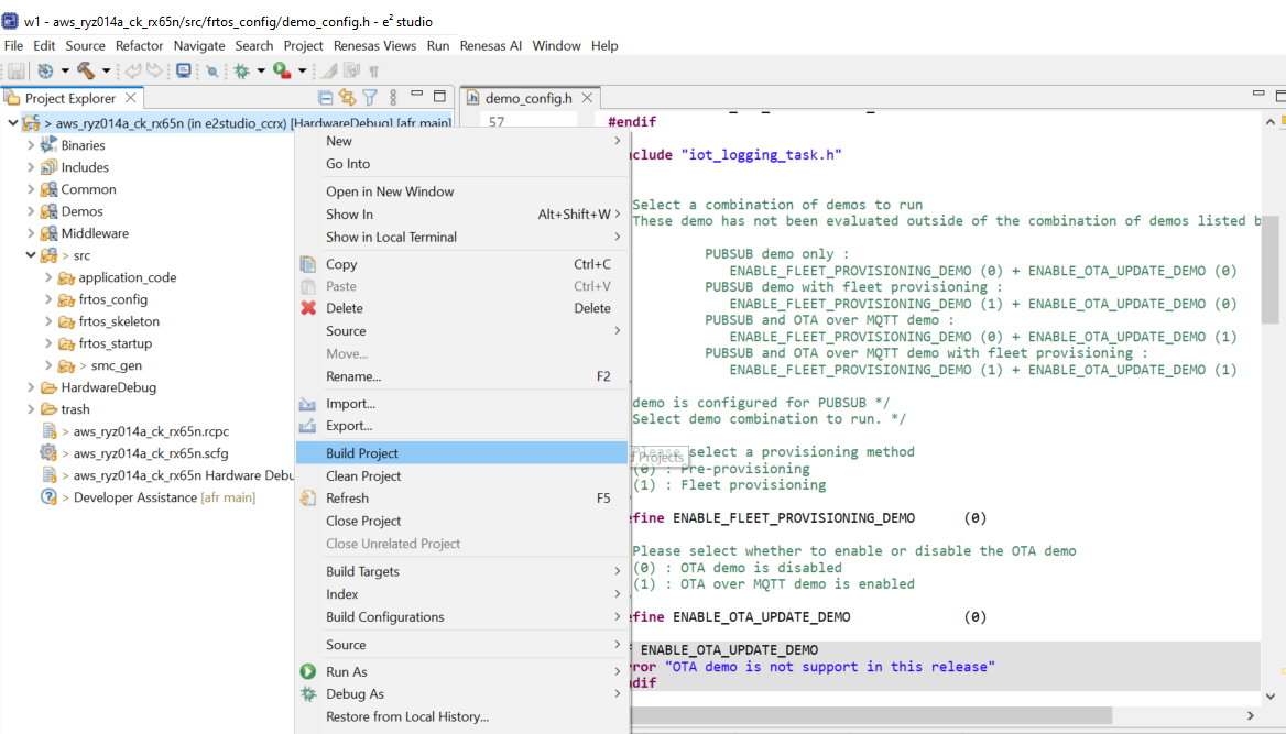
In "Projects\<project_name>\e2 studio_ccrx\src\frtos_config\demo_config.h", configure both of ENABLE_FLEET_PROVISIONING_DEMO and ENABLE_OTA_UPDATE_DEMO, which allow to select the different supported demo combinations:
ENABLE_FLEET_PROVISIONING_DEMO: (0)ENABLE_OTA_UPDATE_DEMO: (0)

The socket wrapper layer provides a hook function to reset the cellular or wi-fi module when an error occurs.
It is recommended to reset the module if the FIT module API "R_Cellular_xxx"/"R_WIFI_xxx" returns errors CELLULAR_ERR_MODULE_TIMEOUT, CELLULAR_ERR_MODULE_COM in case of Cellular or WIFI_ERR_MODULE_COM in case of Wi-Fi. Otherwise, the module may not communicate.
You can change USER_TCP_HOOK_ENABLED in "Projects\<project_name>\e2 studio_ccrx\src\frtos_config\user_tcp_hook_config.h" to enable or disable this hook.
You can use hook as-is if you only run the demos. In our current implementation, cellular or wi-fi module is reset in this hook when the following conditions:
- On TCP_Sockets_Connect,
- When both errors occur 1 time.
- On TCP_Sockets_Recv and TCP_Sockets_Send,
- In case of Cellular:
- When
CELLULAR_ERR_MODULE_TIMEOUToccurs 1 time. - When
CELLULAR_ERR_MODULE_COMoccurs continuously 3 times.- You can change retry numbers by configuring
USER_COMM_ERROR_TRIES.
- You can change retry numbers by configuring
- When
- In case of Wi-Fi:
- When
WIFI_ERR_MODULE_COMoccurs 1 time.
- When
- In case of Cellular:
Configure the Renesas code generator (RX Smart Configurator*).
Please open RX Smart Configurator* and configure settings according to the image below.
Select aws_ryz014a_ck_rx65n.scfg --> Components --> Icon for adding components --> Configure general settings... --> Component --> code generation behavior column --> Update configuration files.

*See the manual of RX Smart Configurator for details on how to use it. The Config files generated after code generation by RX Smart Configurator are exist in the following folder:
- "Projects\<project_name>\e2 studio_ccrx\src\smc_gen"
Download FreeRTOS Kernel and FreeRTOS LittleFS.
If FreeRTOS kernel and FreeRTOS LittleFS is not installed, the icon will be displayed as a gray square as shown in the image below.
If you have already installed the FreeRTOS kernel and FreeRTOS LittleFS, please skip the download step.
FreeRTOS kernels can be downloaded using RX Smart Configurator.
Click on FreeRTOS_Kernel and then select downloading it.

FIT modules can be downloaded in the same way.
Select the FIT module you wish to download, and then download it from downloading it.
If you have also installed FIT, please skip this step.
Use the RX Smart Configurator to configure the SIM card settings.
Open the RX Smart Configurator as shown in the image below and set the four parameters "Access point name", "Access point login ID", "Access point password", and "SIM card PIN card PIN code".
The settings will vary depending on the SIM card that you are using, so please check the SIM information.
"Access point name": Set the access point name of the SIM"Access point login ID": Set the user name of the SIM"Access point password": Set SIM card password"SIM card PIN code": Set SIM card PIN code
If you are using the truephone SIM that comes with CK-RX65N v2, it will work if you only enter the Access point name.

Configure settings related to the bands supported by your cellular module. In case of RYZ014A, configure the following macro in "Middleware\network_transport\sockets_wrapper\ports\cellular_ryz014a\TCP_socket_hook.c"
CELLULAR_BAND_CONFIG: Set"1,2,4,5,8,12,13,14,17,18,19,20,25,26,28,66"
Use the RX Smart Configurator to configure the Country code and GMT timezone.
Open the RX Smart Configurator as shown in the image below and set the 2 parameters "WIFI_CFG_COUNTRY_CODE" and "WIFI_CFG_SNTP_UTC_OFFSET".
"WIFI_CFG_COUNTRY_CODE": Country code defined in ISO 3166-1 alpha-2 standard. Such as KR, US, JP, and CH."WIFI_CFG_SNTP_UTC_OFFSET": GMT timezone offset in hours (-12 ~ 12).

Configure settings of Wi-Fi network for Wi-Fi DA16600 module. Configure the following macro in "src\application_code\include\aws_clientcredential.h"
clientcredentialWIFI_SSID: Set the access point name of Wi-Fi networkclientcredentialWIFI_PASSWORD: Set the Wi-Fi network password
/*
 * @brief Wi-Fi network to join.
 *
 * @todo If you are using Wi-Fi, set this to your network name.
 */
#define clientcredentialWIFI_SSID                    ""

/*
 * @brief Password needed to join Wi-Fi network.
 * @todo If you are using WPA, set this to your network password.
 */
#define clientcredentialWIFI_PASSWORD ""Build firmware image by the builder with e2 studio.
In the Project Explorer pane of e2 studio, Right click on the project and select Build Project. Wait for completing building.
Note: Or choose Project->Build Project menu to build.
RSA key pair and device certificate can be generated with AWS Console when creating new iot-thing. For more information about create iot-thing with Auto-generate a new certificate, please refer to the following webpage: https://github.com/renesas/iot-reference-rx/wiki/Register-device-to-AWS-IoT
If you follow the steps in the URL, the following three files will be generated.
- xxxx-certificate.pem.crt
- xxxx-public.pem.key
- xxxx-private.pem.key
Configure Tera Term settings as following if you use it:
-
New line configuration: Setup->Terminal->New-line
- Receive : AUTO
- Transmit: CR+LF

-
Serial port settings: Setup->Serial port
- Port : Your COM
-
Baudrate : 115200
-
Data : 8 bit
-
Parity : none
-
Stop: 1 bit
-
Flow control : none

Flash firmware image to your target device by the either of following ways.
In the Project Explorer panel of e2 studio, right click on the project and select Debug As --> Renesas GDB Hardware Debugging.
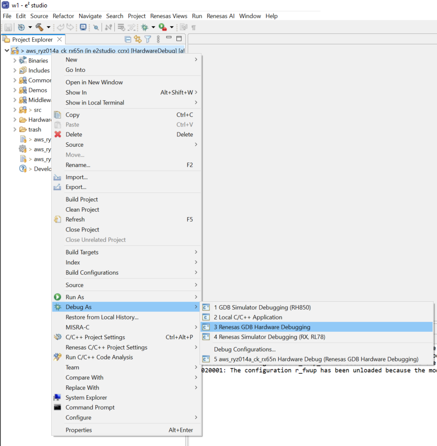
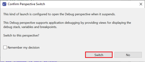
If the window below appears, press "Switch".
Press the following button to start debugging.
The first command of step 4-1-6 must be entered on teraterm within 10 seconds after the start of debugging.
It is recommended that you have teraterm ready for easy input.

CLI runs on the serial terminal application when starting demo. Input the following commands to the serial terminal application to start communication to AWS.
The summarized flow of the command input is as follows:
- Switch CLI mode.
- Set IoT information (thing name and MQTT endpoint).
- Set security information (device certificate and private key).
- Commit preceding changes.
- Reset and restart demo.
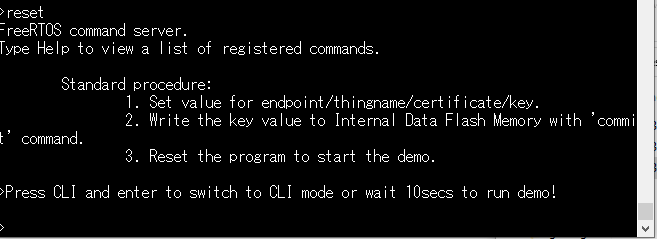
CLI automatically runs just after starting demo. First, Switch to CLI mode by inputting the following command:
> CLI
Going to FreeRTOS-CLI !

Note: CLI will timeout after some seconds. If timeout occurs, core process of demo runs.
Next, format the Data Flash:
> format
Format OK !

Next, configure the desired thing name / mqtt device identifier:
> conf set thingname github_thing_en
OK

Next, set the mqtt endpoint to the endpoint for your account:
> conf set endpoint xxxxxxxxxxxxxx-ats.iot.us-west-2.amazonaws.com
OK

Note: You can determine the endpoint for your AWS account with the aws iot describe-endpoint command or on the Settings page of the AWS IoT Core console.
Next, set the device certificate:
Drag and drop "xxxx-certificate.pem.crt" generated in Step 4-1-3: Create RSA key pair and device certificate for PubSub demo to teraterm.
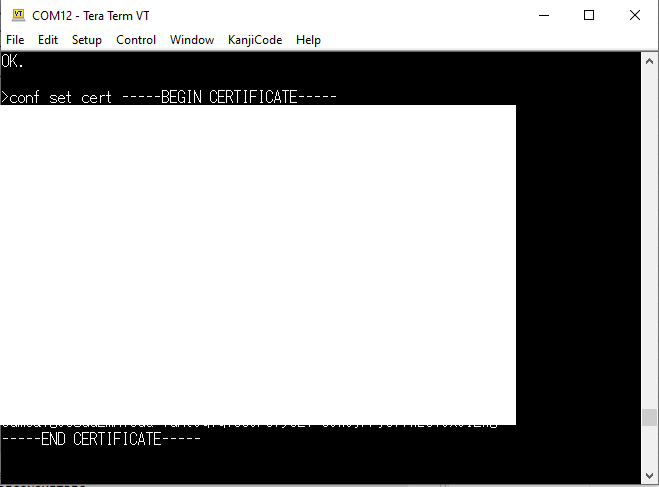
Note: About <device certificate>, if you use TeraTerm, drag and drop the certificate file onto the Terminal screen after entered conf set cert , then select Send File (Paste content of file) on the screen that appears, and press OK. The contents of the certificate file will be entered.
Next, set the device private key:
Drag and drop "xxxx-private.pem.key" generated in Step 4-1-3: Create RSA key pair and device certificate for PubSub demo to teraterm.

Note: About <private key>, if you use TeraTerm, drag and drop the certificate file onto the Terminal screen after entered conf set key , then select Send File (Paste content of file) on the screen that appears, and press OK. The contents of the certificate file will be entered.
Next, commit the staged configuration changes to Data Flash:

Finally, reset the target device once by the following command to restart demo:
> reset
After restart demo, wait a seconds with input nothing via CLI. Then demo is performed with the following output.
-
PubSub Demo Task 0 and PubSub Demo Task 1 can complete successfully.

-
You can get message "Hello World" published to MQTT test client console (https://us-east-2.console.aws.amazon.com/iot/home?region=us-east-2#/test).
Enter "#" on the AWS console and press "Subscribe".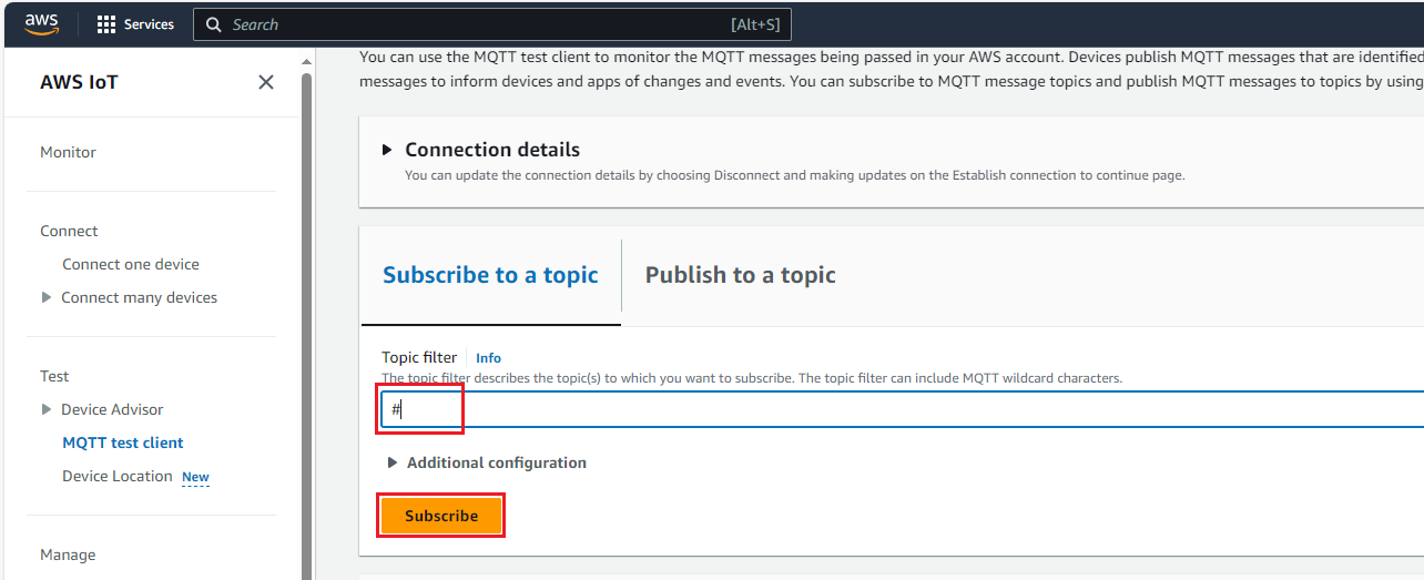 If successful, it will be displayed on AWS conclose as shown below.
Details for PubSub demo with Fleet Provisioning are provided in the special application note (document number: R20AN0674). You can search it by visiting the following webpage:
About how to run this demo, see the chapter 4. Running the Fleet Provisioning Demo in preceding application note. Or watching the following video:
Though this application note is for both Ethernet and Cellular projects, Wi-Fi project will also work as described in application note.
When running this demo, please enable Settings of RX Smart Configurator before generating code with RX Smart Configurator.
- Make sure to follow the steps described in the preceding application note.
- If you deviate from the normal flow, the Data Flash usage is not guaranteed.
- The following is an example of Fleet Provisioning with abnormal flow:
- When demo program enters CLI mode first time, set and commit claim credentials, endpoint, template and rootCA information as usual.
- After Fleet Provisioning and PubSub demo completes, reset the device.
- When demo program enters CLI mode again after reset, set and commit a new set of device credentials.
- With the normal flow, Data Flash usage is ~7808 bytes after Fleet Provisioning.
- With the abnormal flow, new device credentials will overwrite existing credentials provisioned by Fleet Provisioning.
- In this case, an additional 1408 bytes will be used.
- Currently the maximum response latency between AWS and the device is set at 5000 ms.
The latency is set to be long enough to allow for a margin of error.
If you want to shorten the latency, please adjust it according to your environment.
Demos\common\Mqtt_Demo_Helpers\mqtt_pkcs11_demo_helper.c
mqttexamplePROCESS_LOOP_TIMEOUT_MS (5000U)
Details for Pubsub demo with OTA are provided in the special application note (document number: R20AN7037). You can search it by visiting the following webpage:
About how to run this demo, see the chapter 2. Prerequisites in preceding application note.
Though this application note is for both Ethernet and Cellular projects, Wi-Fi project will also work as described in application note.
The "boot_loader_ck_rx65n_v2" project should be used when running this demo on CK-RX65N v2.
When running this demo, please enable Settings of RX Smart Configurator before generating code with RX Smart Configurator.
If an error occurs during cellular or wi-fi communication due to the communication environment, changing each definition to the following "correction value" may improve the problem.
| Definition Name | Description | defalt value | correction value | path |
|---|---|---|---|---|
| mqttexampleTRANSPORT_SEND_RECV_TIMEOUT_MS | Timeout in milliseconds to send and receive in the transport layer. You try to change the value to more big when you met TLS handshake error. Changes in this value affect the time of MQTT communication. A change in the MQTT communication time may increase or decrease the OTA process time. So you should adjust the value of time according to your communication environment. | 450 | 750 |
Demos\mqtt_agent\mqtt_agent_task.c |
| MQTT_AGENT_MAX_EVENT_QUEUE_WAIT_TIME | Time in milliseconds that the MQTT agent task will wait in the Blocked state (so not using any CPU time) for a command to arrive in its command queue before exiting the blocked state so it can call MQTT_ProcessLoop(). | 50U | 1000U |
src\frtos_config\core_mqtt_agent_config.h |
However, each definition affects the execution time of the demo.
If the above values are set, the execution time of the demo may increase.