(Many thanks to Cole Juckette for his help with Exercise 5!)
A step-by-step video of the 'Mesh Collider' version of this exercise can be found here.
A more advanced approach to creating an interactive reconstruction of Malthi is to use a game engine, like Unity, to essentially make a walking simulator of the site. Though Sketchfab is a very simple and quick way to get your 3D assets out into the world, Unity offers significantly more freedom in what is possible to create.
Think and Respond: Before you start this optional activity, reflect on your own learning objectives. Do you feel that the additional work and time investment that you will put into learning this new skillset is worth the range of possibilities Unity offers for archaeological reconstructions? Which features offered by Unity (and not offered by Sketchfab) do you think are particularly important for interpreting reconstructed archaeological sites?
You will need to make an account to access the Unity Asset Store, and you can install Unity from this link. In the asset store, you will want to find the most up-to-date, free ‘First Person Character Controller’ (preferably made available by Unity Technologies). At the time of writing, this could be found at this link, but be sure that you familiarise yourself with how the Unity Asset Store functions.
You will also need to make some decisions about how you want your game to appear – do you want the normal maps intact on your laser-scanned datasets, and simply apply a Mesh Collider? Or would you prefer to utilise Unity’s Terrain Engine to add more detail to your landscape/reconstruction?
There are a few things that will need to be prepared before importing everything into a Unity project. First, ensure that the reconstructed assets are exported separately from the laser scanned dataset. Secondly, make sure that your base map is decimated to about 1 million faces or so – this will result in a file size that is around 80 MB. Smaller file sizes mean that your ‘game’ will run more smoothly.
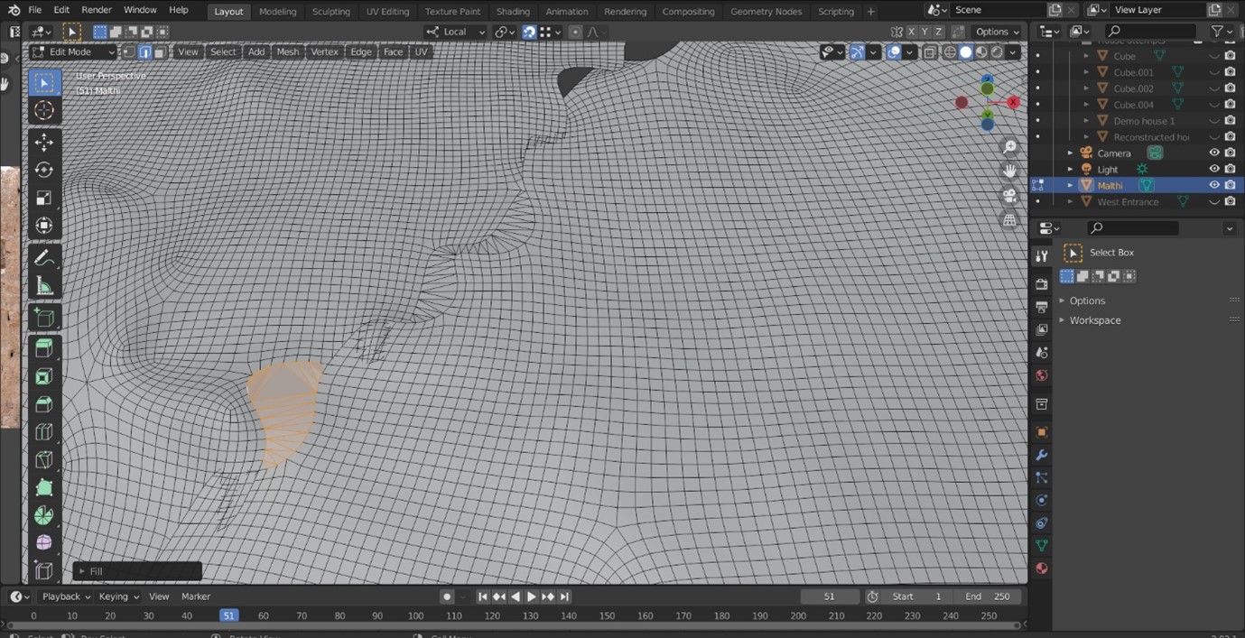
Finally, you need to ensure that most large holes (most of which arise from merging segments of the laser scan data) are filled. Because this involves filling the holes between what used to be two separate ‘objects’, you need to use the ‘Bridge edge loop’ tool instead of just using the ‘Fill’ tool in Blender. This is to prevent your user’s ‘character’ from falling into holes in the terrain.
- In edit mode, select two edges that are close to each other, but belong to the two meshes you are attempting to join. (Do this by holding shift while left-clicking each edge.)
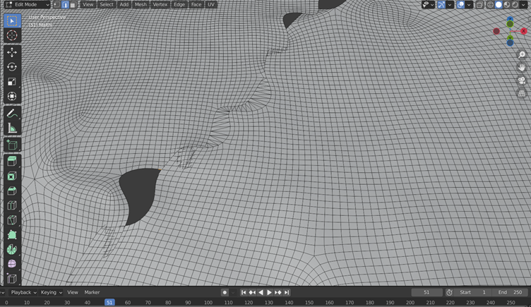
- Right-click anywhere in the scene, then select ‘Bridge Edge Loops’ from the menu that appears.
- Repeat this at the other ‘end’ of the hole – you want to ensure that you have created an ‘Open Loop’ between the two meshes.

- You should now be able to select the loop by holding ‘Alt’ and left-clicking inside or near the edge of the hole. If it does not select the whole loop automatically, use a series of ‘Ctrl + left click’ to build a loop through the ‘Shortest path’ function.
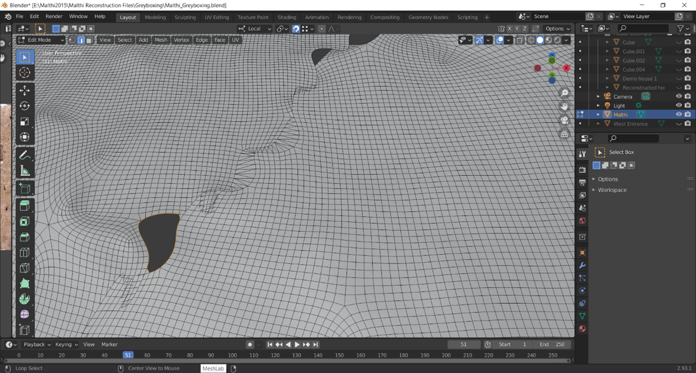
- Finally, use ‘Alt+F’ or right-click anywhere and select the ‘Fill’ tool.
Once your data is ready, export them into either the FBX or OBJ format. While you can import the entire BLEND file into Unity, at the time of writing this was still less reliable than exporting the files directly.
Now that your files are ready, you’ve installed Unity on your computer, and you’ve added the First Person Controller to your Unity assets, you are ready to begin building in Unity.
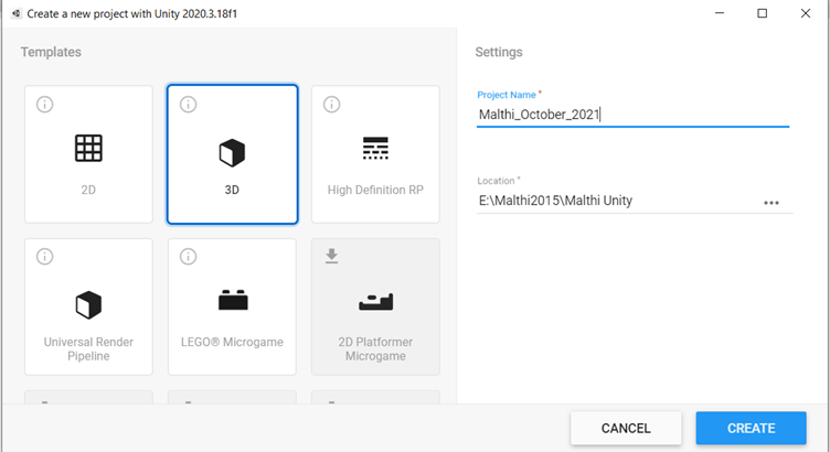
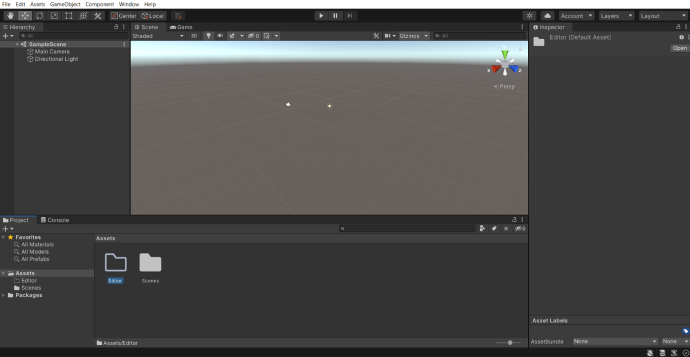
First, open Unity. You will be greeted with a pop up like the one below (note that this Exercise will be providing examples from version 2020.3.18f1). Choose a 3D Template, name your project and choose where to save it. It will then take some time to create the project.
Now that you have created your blank Unity project, here are a few basic controls you will need to get used to:
- Left click: Select assets
- Clicking and dragging the mouse wheel: Pan
- Right click and drag: Rotate 3D view (not to rotate the 3D model)
- To move/rotate the 3D assets, use the toolbar in the top left corner of the Unity interface:
More of Unity’s controls can be found in its Documentation here.
If you wish to keep your laser scan data looking exactly as it did in Blender, you can add what is called a ‘Mesh Collider’ to your scan data to allow your user to ‘walk’ on the site. First, let’s import your assets.
When Unity opens the 3D Template, you will see a few familiar-looking areas. For one, it has a ‘Hierarchy Window’ much like Blender, where you can find all of the ‘layers’ or individual ‘assets’ in the project. There is a ‘Project Window’ at the bottom of the screen, where you will likely see a sole ‘Assets’ folder. Open the assets folder, and drag your decimated, normal-mapped laser scan data into the ‘Assets’ folder.
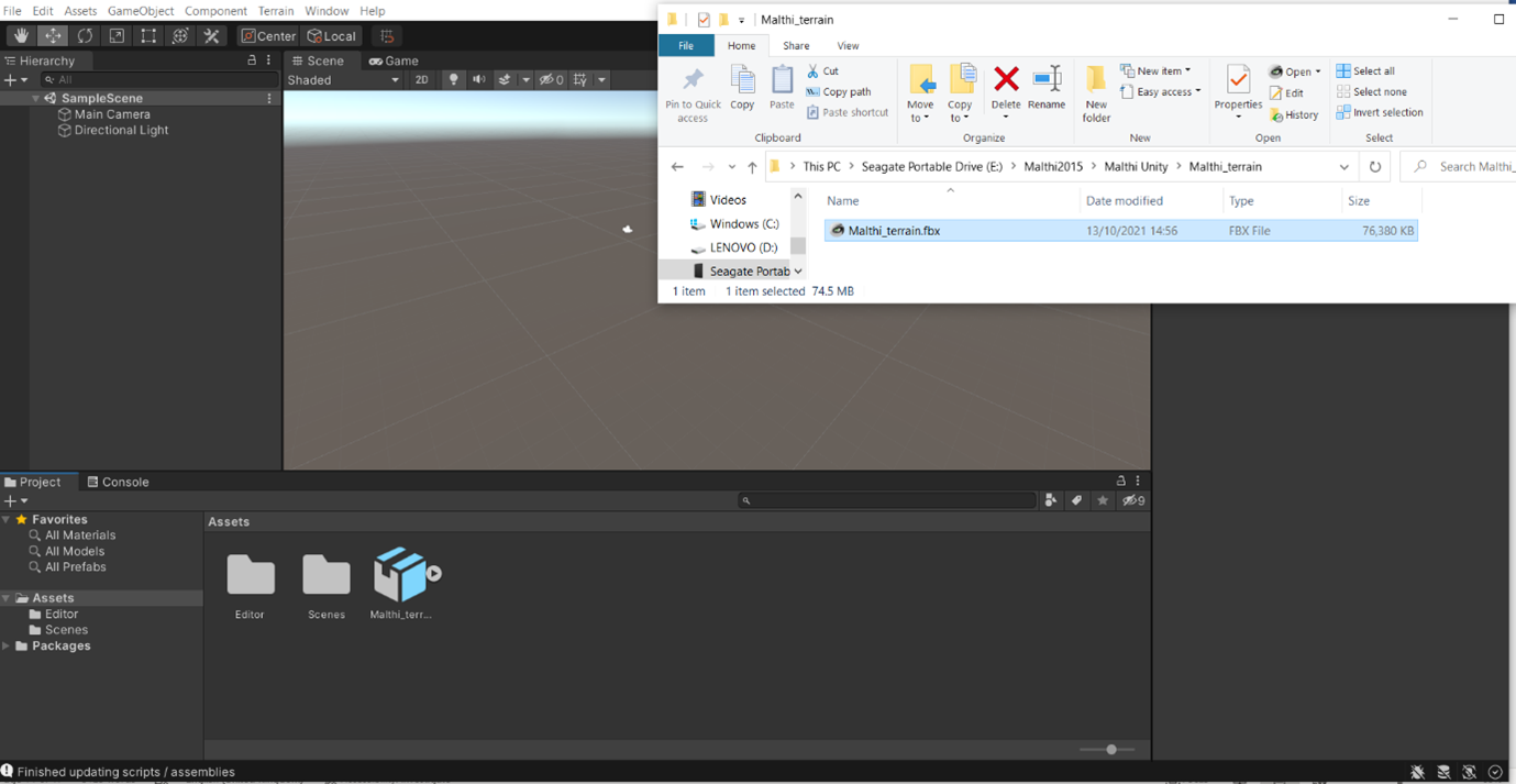
Once your 3D data is in the ‘Assets’ folder, you can click and drag it directly into the ‘Scene’ window.
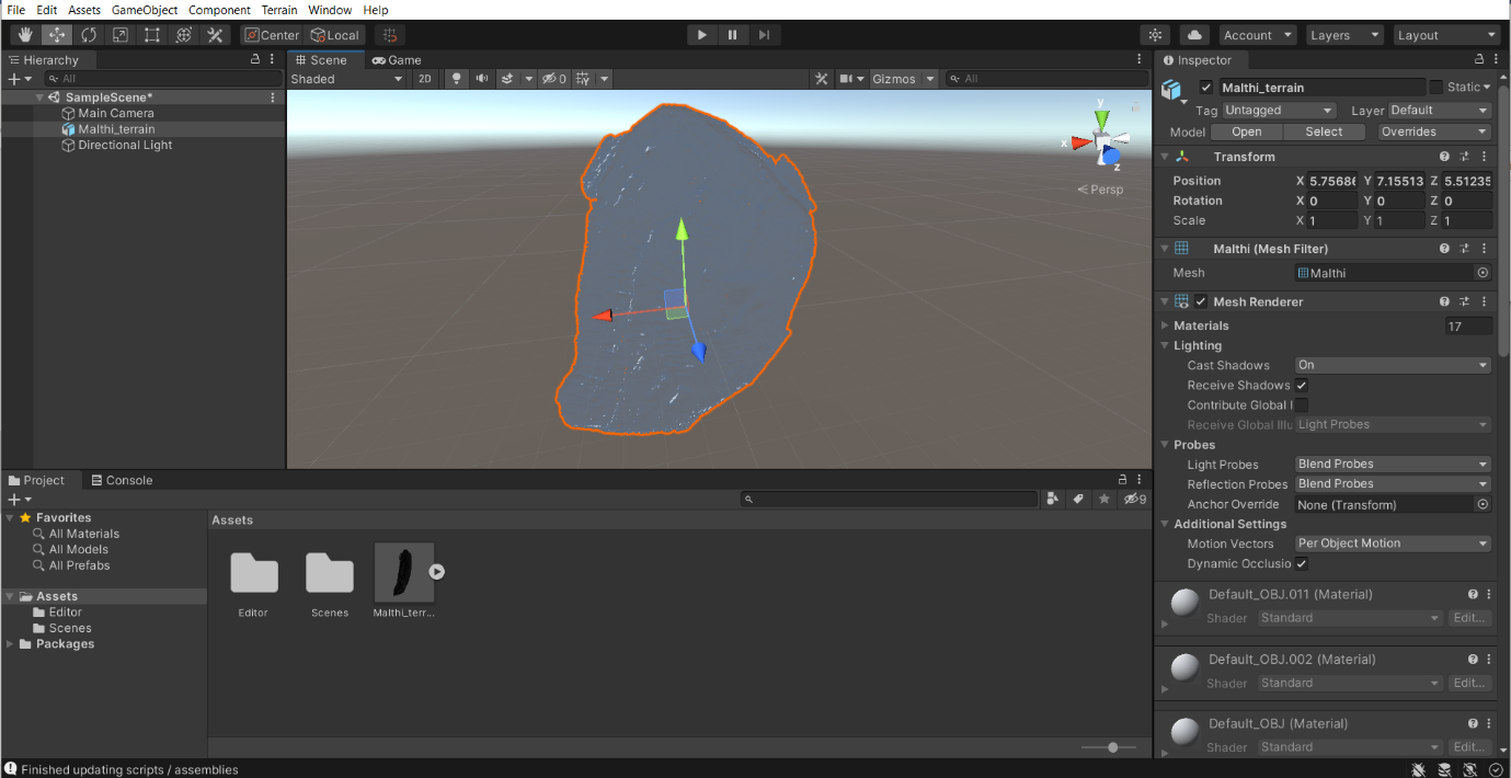
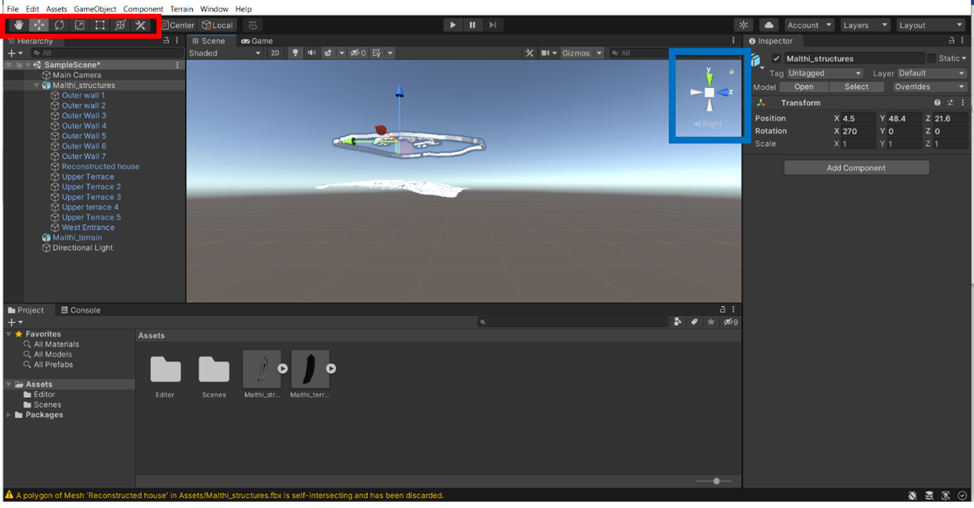
Now, let’s rotate the model so that the surface of the site is pointing up (note that the Y axis is up in Unity). Select the Malthi model and the ‘Inspector Window’ will provide many options. Under ‘Transform’, change the rotation of the X Axis to 270.

Next, copy over your ‘Structures’ in the same way, and apply the same transformation so that they are roughly aligned with your site.
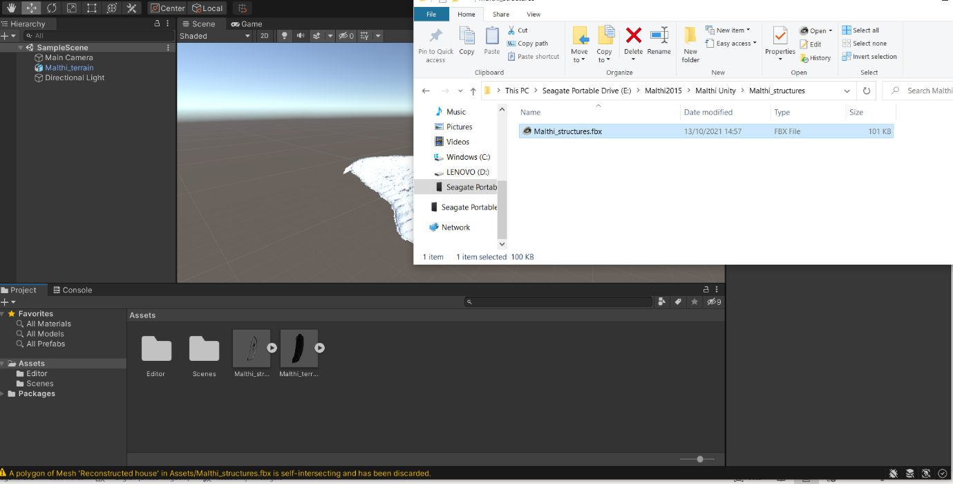
When we place the structures into the scene, they will not be perfectly aligned with the site.
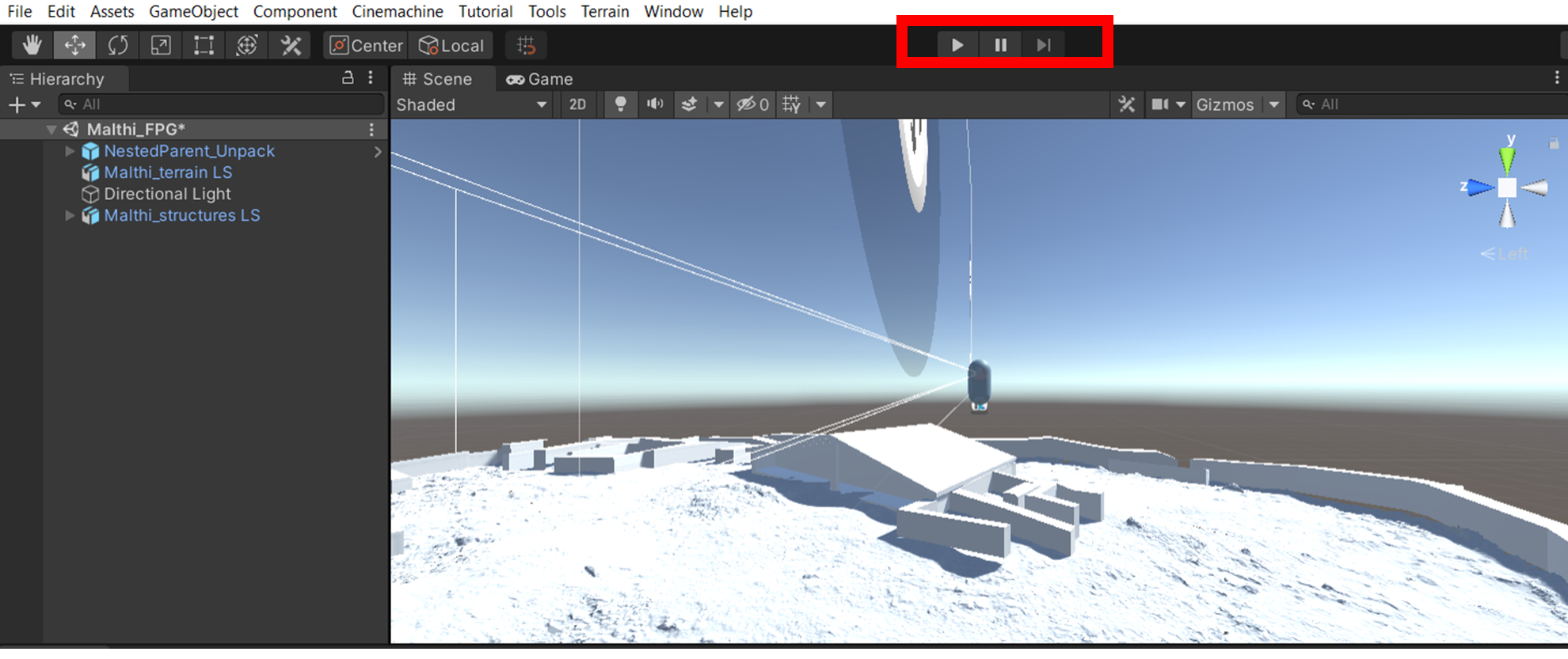
- You can use ‘Transform’ to position them in roughly the correct place, but undoubtedly you will still need to use the ‘Move’ and ‘Rotation’ tools (highlighted in the red box below) to place them perfectly. Left-click and drag the arrows to move the features along one axis; the same can be done with the rotational tool (left-click and drag one coloured circle to rotate the 3D data along one axis).
- Like in Blender, you can use the navigational gizmo to align yourself above Malthi by clicking the ‘Y’ cone (highlighted with a blue box below).
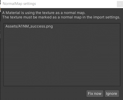
Now you may want to add your normal maps to the Unity project – you can either drag all of your normal maps into the Asset folder (like you did with the 3D objects), or create a new folder for them. When you import your normal maps, Unity should automatically identify that they are normal maps, because they were attached to your 3D model in Blender as ‘Materials’; Unity should automatically identify this reference. This triggers a pop up window, with Unity asking if you want to ‘fix’ them – click ‘Fix now’ and these will become associated with your laser scanned data.
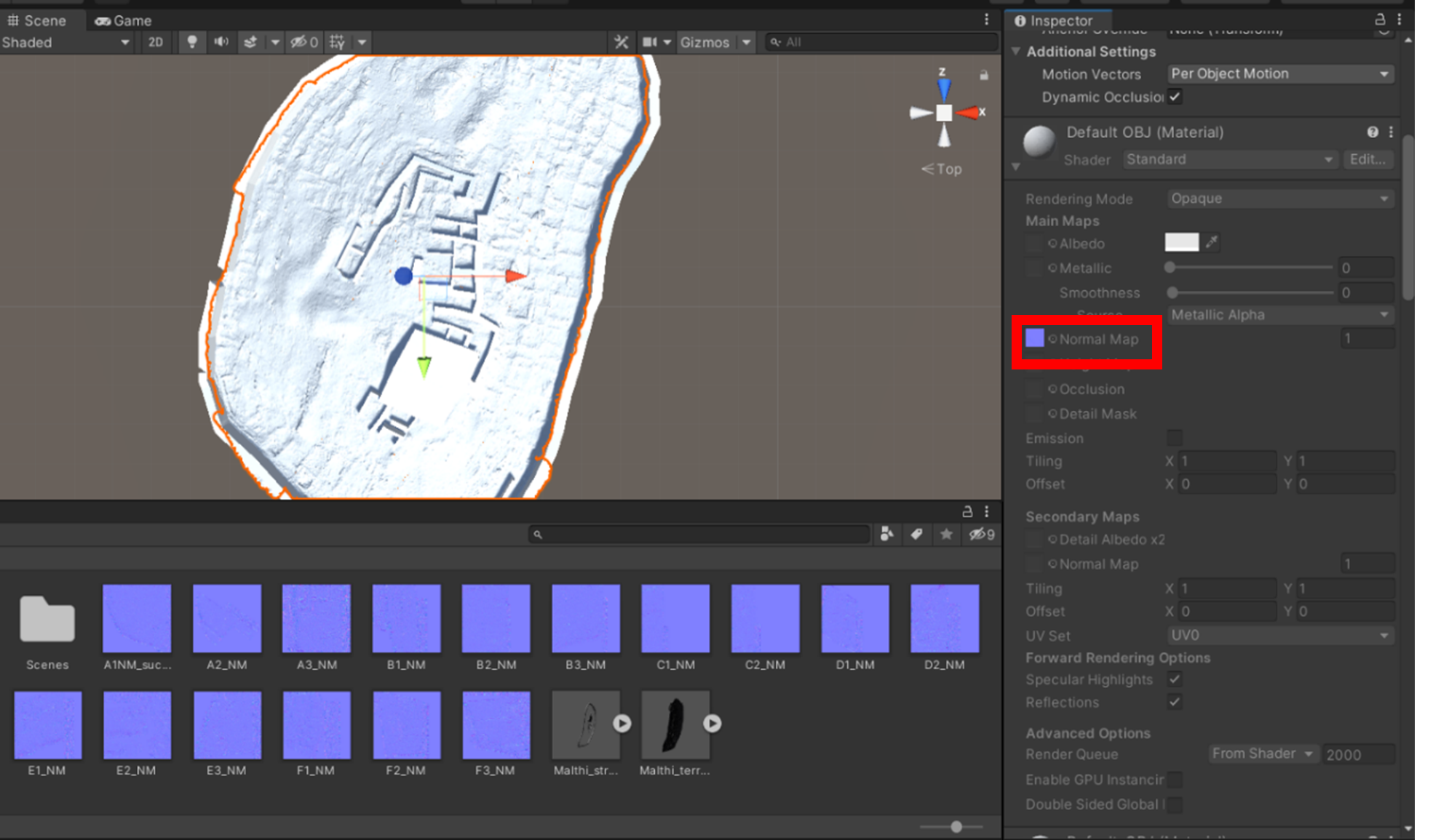
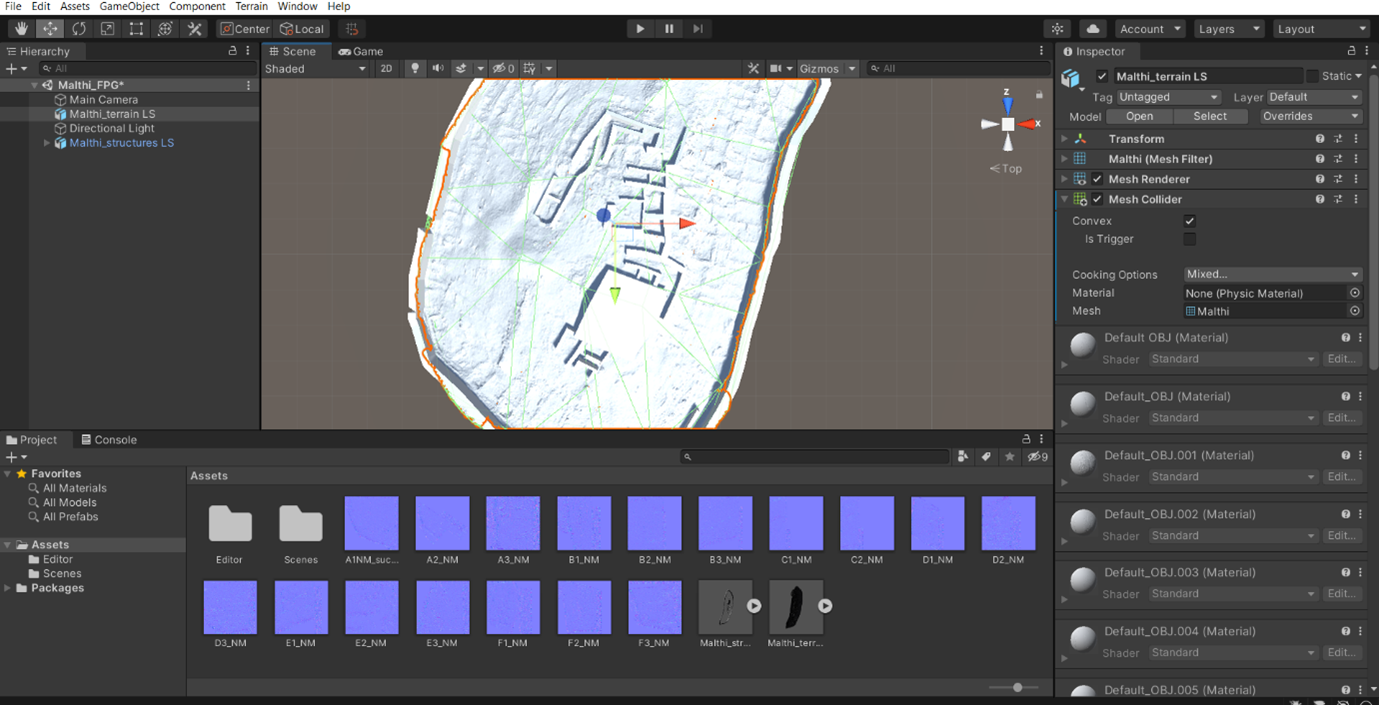
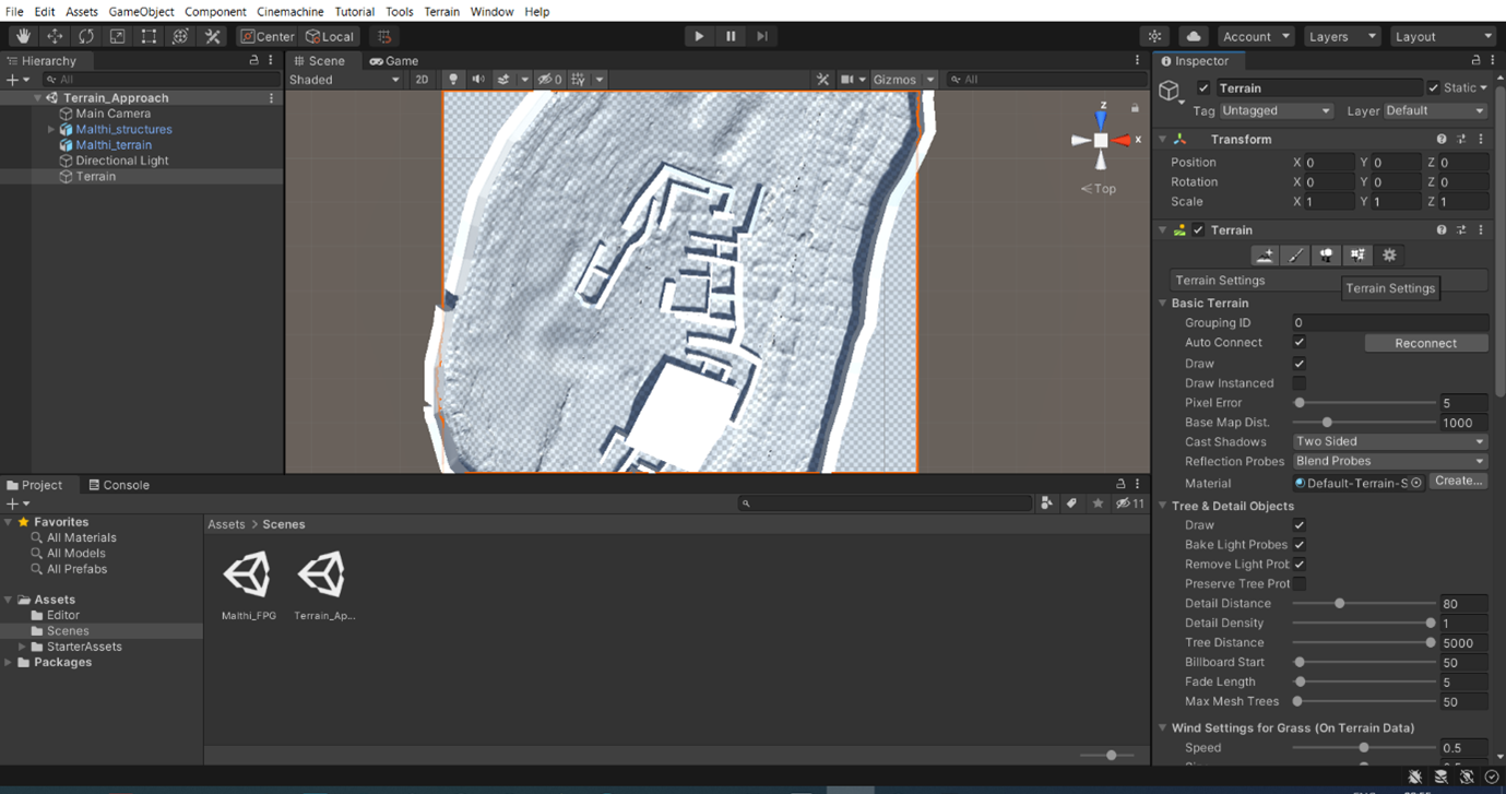
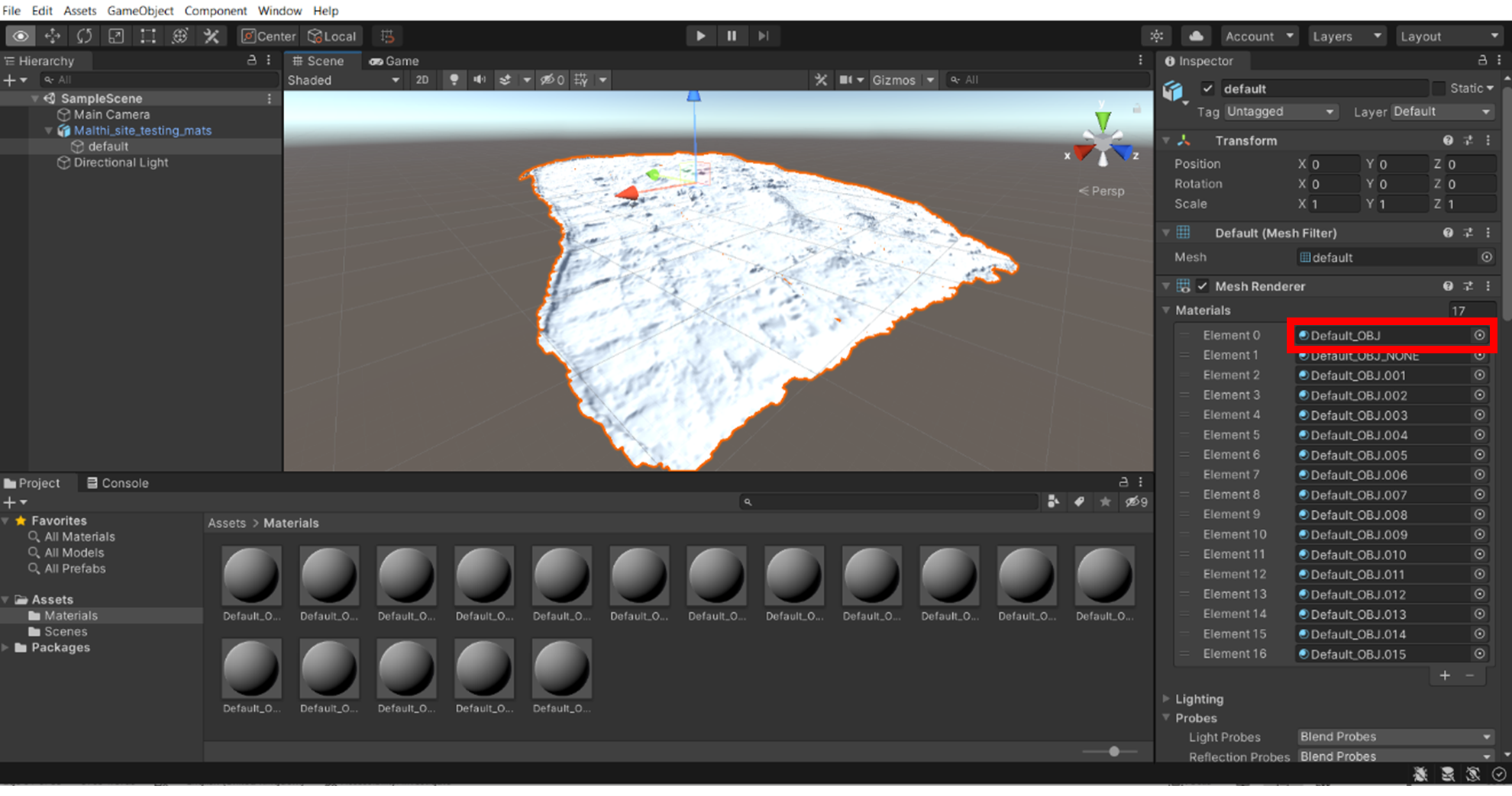
If something doesn’t look quite right, you can check the ‘Inspector’ for your laser scanned data – for each dataset that you broke down the original laser scan data into, there will be a specific material slot. If you open this ‘material slot’ as in the image below, you can check that the correct Normal map has been assigned by clicking on the normal map slot (highlighted with a red box) – it will highlight the normal map that is assigned to this material slot in the ‘Assets’ folder.
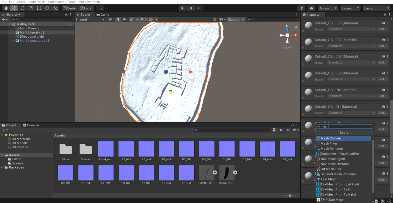
Now, to ensure that the user will be able to walk on your laser scan data, we need to add something called a ‘Mesh Collider’. This will ensure that the laser scan data is treated as a ‘solid surface’, enabling characters to ‘collide’ with the site data. To add a Mesh Collider to your laser scan data, ensure that your mesh is highlighted and its details are visible in the Inspector. In the Inspector window, scroll all the way down to the ‘Add Component’ option. Then, search for the ‘Mesh Collider’ component, as shown below. Select Mesh Collider, and it will be added to the list of components (likely above the material slots). Once this is applied, check the ‘convex’ box. This process may take some time to complete.
At this point, you have now converted your laser scan data into a ‘solid surface’ for your users to (eventually) navigate! If you are happy with this, skip to the ‘Adding the First Person Controller’ section below.
If, instead of wanting to keep your normal maps, you want to work with Unity’s ‘Terrain Engine’, you will first need to convert your laser scan mesh into a ‘Terrain’. Unfortunately this is not an inbuilt function in Unity, so you will need to download the ‘Object2Terrain’ script. While it is not recommended that you download scripts from sketchy sites, this particular script is recommended by a wide variety of online tutorials (and me).
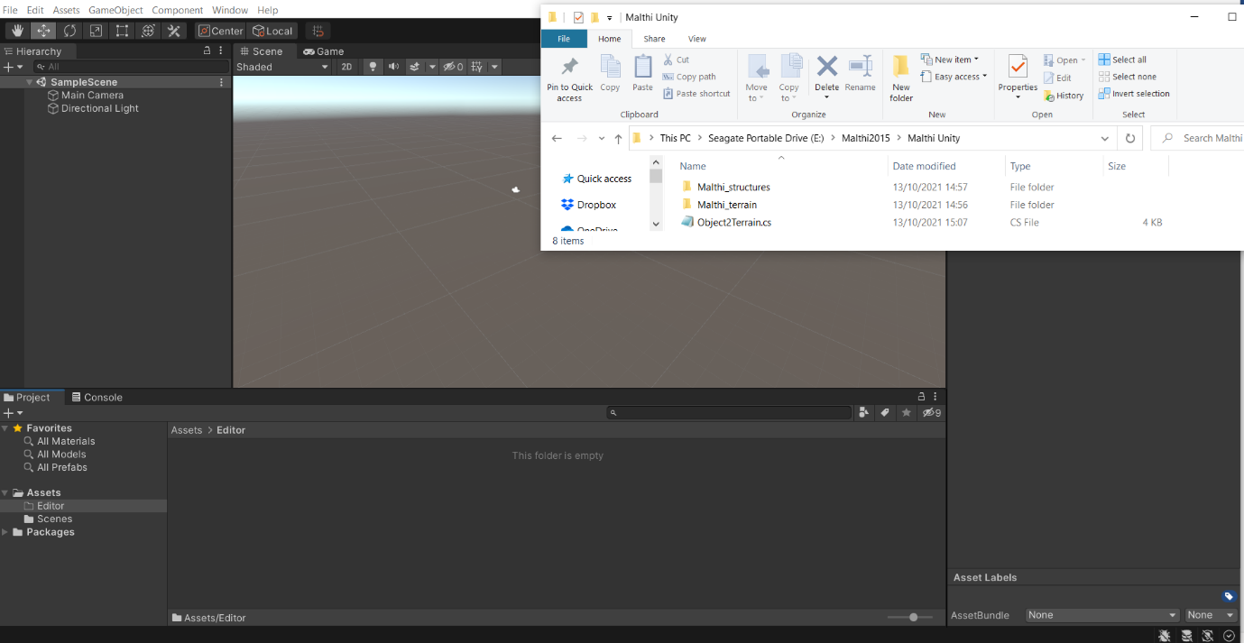
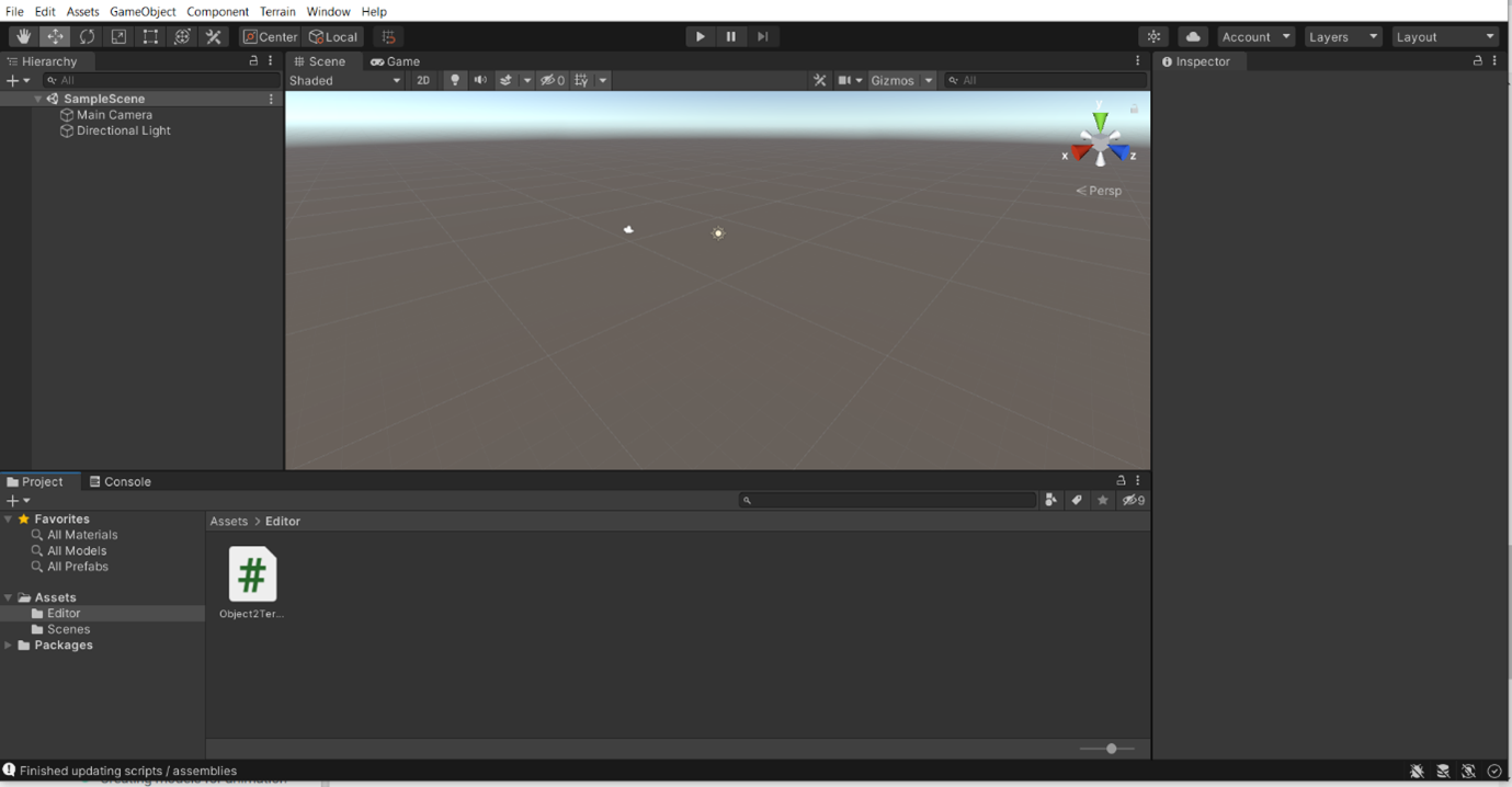
- Once you have acquired this script, right click in your Assets folder and ‘Create > Folder’. When you name this folder, name it Editor – ensure it has a capital E and that you’ve spelled it correctly, otherwise the script will not work.
- Open the newly created Editor folder, then click and drag the ‘Object2Terrain’ script into the Editor folder.
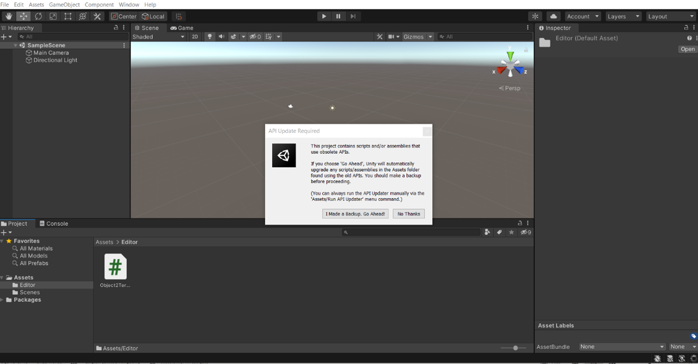
- Unity will then ask if you consent to the script updating – say yes to these and other pop ups that might appear.
- Once this has completed, note that there is a new menu item added to Unity called ‘Terrain’. This has been added by the script.
- Now add your assets – Open the main Assets folder, and drag your decimated laser scan data into the ‘Assets’ folder.
- Drag your mesh from the ‘Assets’ folder into the 3D Viewer.
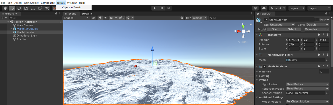
- With your mesh highlighted, rotate the model so that the surface of the site is pointing up (note that the Y axis is up in Unity). The ‘Inspector Window’ will provide many options. Under ‘Transform’, change the rotation of the X Axis to 270.
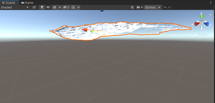
- Take note of the grid that you can see in the scene – to create a terrain, you want your original mesh to be located above the grid. Use the ‘Move’ tool – drag up on the arrows that appear on the mesh until the grid lines are clearly positioned below the mesh.

- Once you are certain the mesh is positioned above the grid, ensure that the laser scanned mesh is highlighted. Then, navigate to the ‘Terrain’ drop down menu, and select ‘Object to Terrain’.
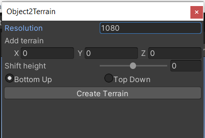
- Selecting ‘Object to Terrain’ will prompt a new dialog box to appear. It asks for you to set the resolution of your terrain (the example mesh has been set to 1080), along with a few other options. Ensure that ‘Bottom Up’ is selected, as the script will prompt Unity to extrude a mesh to match the current elevation of your mesh (essentially, it will project a terrain mesh upwards from the grid, until it matches/adheres to the contours of your decimated mesh).
- It is important that you do not exceed 2000 for any of the values in this dialog box, as this may cause the software to crash.
- After the script completes, a new mesh will appear in the 3D viewer (likely in a check-box texture, as shown below). This is your new terrain, derived from your decimated mesh. This will now enable you to easily apply textures to your mesh and to use the Terrain tools built into Unity’s interface.
- Now, add your structures to the Assets folder like you did with the original mesh. Drag these into the 3D viewer and align it with your Terrain.
- Make sure you save!
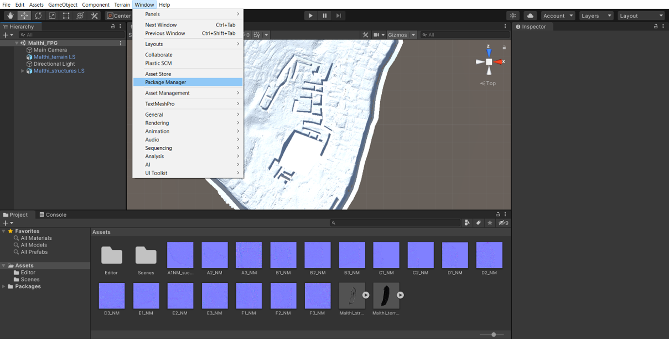
Whether you decided to go with the ‘Terrain’ or the ‘Mesh Collider’ approach to creating the floor of your experience, you can now add your user’s first-person player character. To do this, navigate to the ‘Window’ option and select ‘Package Manager’. (Note: The following instructions assume that you have added a first person player controller from the Unity store, as outlined at the start of this exercise.)
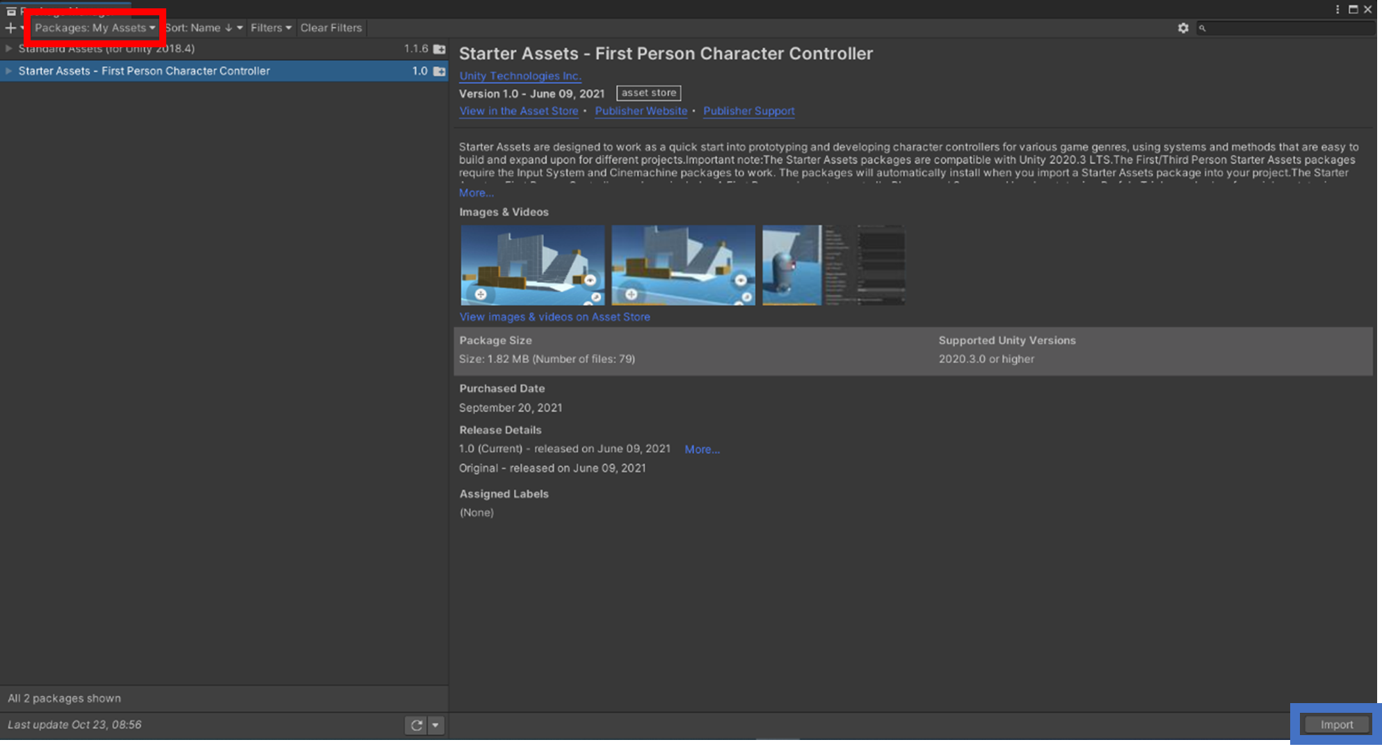
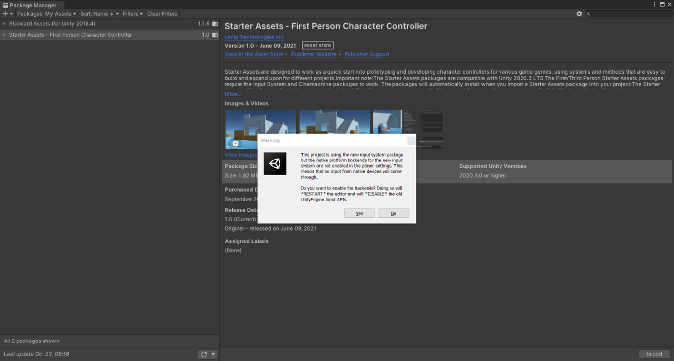
In the Package manager, change the ‘Package’ drop down menu to ‘My Assets’ (highlighted with a red box below). From here, choose ‘Starter Assets – First Person Character Controller’ and click ‘Import’ in the bottom right hand corner (highlighted with a blue box below).
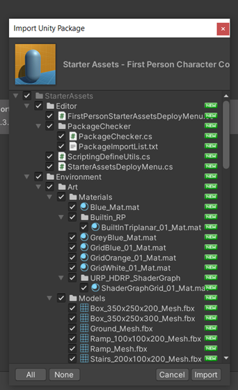
Unity will then take some time before coming up with another pop up as shown below, click import again.
Unity will then take some time to add these components to your project. After some time, a new pop up will appear, asking if you want to enable backends. Click YES, which will cause Unity to do some more processing, and then will restart completely.
Be sure to save!
- The Starter Assets have now been added to a new folder called ‘Starter Assets’. In this folder, navigate to the ‘FirstPerson’ folder by double-clicking.
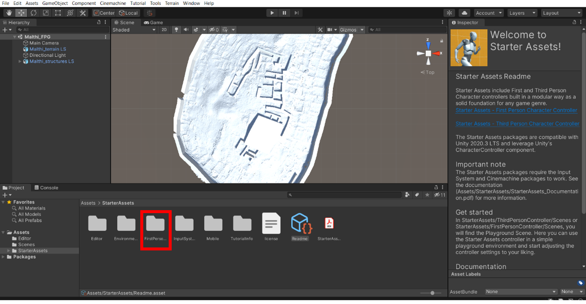
- Then navigate to the ‘Prefabs’ folder. You will want the ‘Nested Parent’ asset. Like you have done with the others, click and drag the controller in, but be sure that you position it somewhere above the site. If you need to reposition it, you will need to zoom out significantly to find the ‘move’ interface on screen.
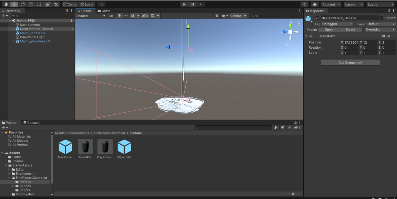
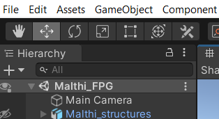
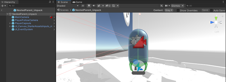
- Take some time to examine the individual components of the ‘Nested Parent’ character – you can do this by clicking the arrow next to it in the ‘Hierarchy’ window.
- Essentially, the capsule acts as the ‘player’, which houses the main camera, which is then directed to ‘follow the player’. There is also the on-screen interface.
- Because there is a camera incorporated into the capsule, we do not need the additional ‘main camera’ that the 3D template started us out with. Go back to the main hierarchy list and delete the ‘Main Camera’ there.
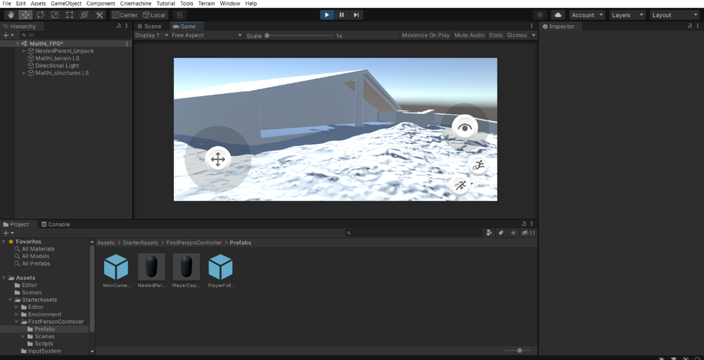
- Now it is time to test your experience! Above your 3D viewport, you may have noticed a ‘play’ button. Press the play button to begin.
- You will now take control of your ‘player capsule’. Move your character in the viewport much like you would most PC games: use the ‘WASD’ keys to move the character, move your mouse to change where your character is looking. The space key will cause the character to jump, and holding a ‘Shift’ key will cause your character to run.
- If you want to exit the ‘test’ phase, hit the ‘Esc’ key to make your mouse visible again, then press either the ‘pause’ button, or press ‘play’ again to reset the position of your first person player controller.
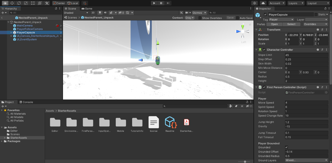
- If you want to change how quickly your character can move, or to change its height, open the ‘Nested Parent’ layer in the Hierarchy window and highlight the ‘Player Capsule’. Under ‘First Person Controller (Script)’, you will see a number of options that you can change.
- Be sure to test after each of these changes you make to see how it affects the experience, because it can cause some problems. For example, if you make it so that your character can move quite quickly, this may cause the camera to ‘clip through’ the player capsule.
Try it yourself! You may have noticed that your character is currently able to move through the walls of your reconstruction. How would you ensure that your player character collides with these structures?
Now that you have the basics in place, you can add further detail. If you went with the ‘Terrain’ option above, you can easily add a ground texture (after adding it to your assets through the asset store, or by downloading a texture from online and dragging it into your assets). Select your ‘Terrain’ in the hierarchy, then under ‘Terrain’, click the gear image. Under the ‘Basic Terrain’ settings, you can set its ‘Material’ to your preferred texture.
If you have instead chosen to keep your normal maps intact, you will already have all of the detail from the original laser scan data preserved. Adding additional textures may occlude those details, but you may wish to add some sort of colour. This is slightly more complicated than the steps above, as you will need to ‘unpack materials’ from the 3D model to make them editable, and then manually reassign your normal maps to each segment again, even if you did this in the steps above. You will need to do this regardless of whether you exported your site map as an OBJ file or FBX file.
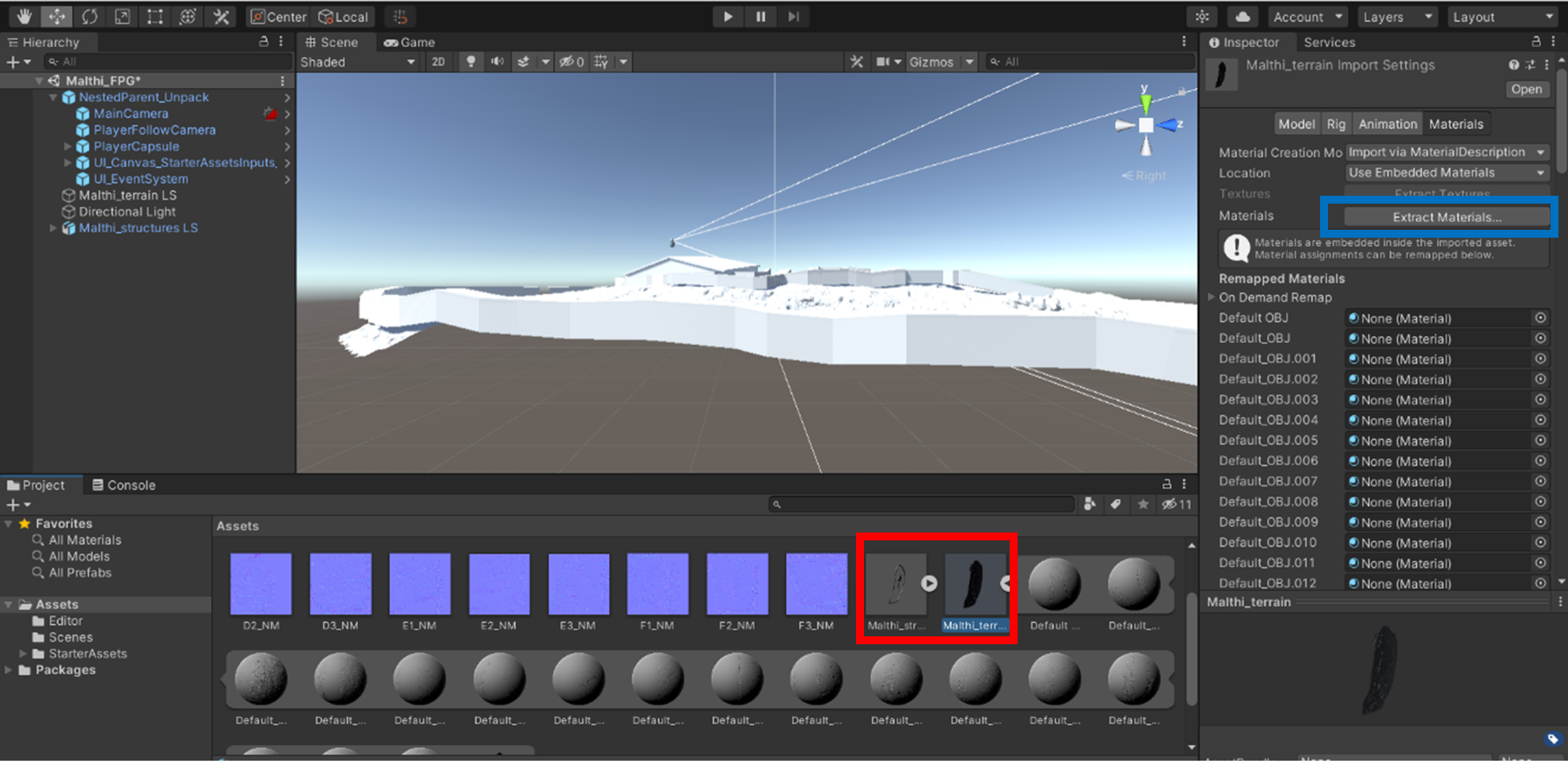
- To make your materials editable, click on your original mesh in the ‘Assets’ folder below (highlighted with a red box) so that the Inspector displays the materials information. Create a Materials folder, then click ‘Extract materials’ from the Inspector (highlighted with a blue box). From the pop up menu, select your materials folder.
- Once the materials are unpacked, click on your mesh in the scene twice to open all of the options available in the Inspector tab. You will now see a Materials drop down menu under ‘Mesh Renderer’ that are interactable. Double-click on one of the materials to open the inspector for that material (highlighted with a red box below).
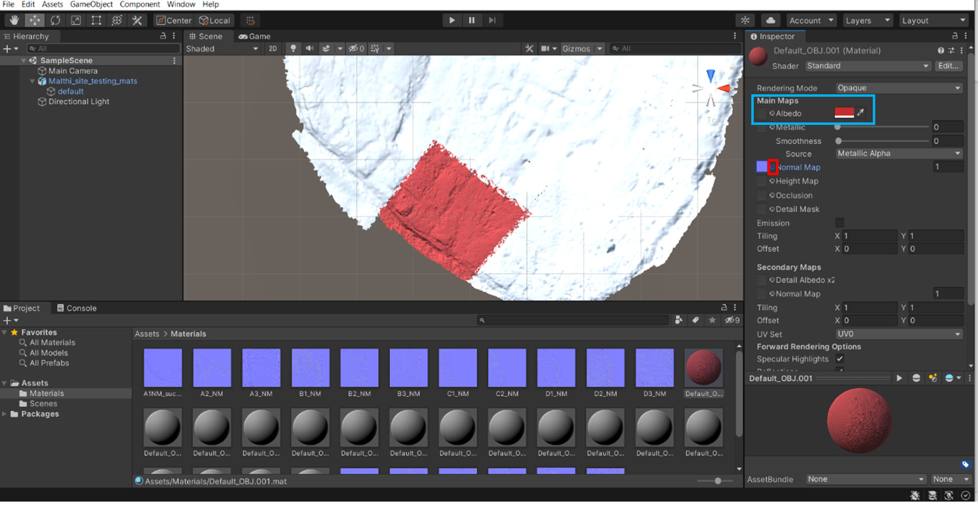
- If you haven’t already, ensure that your normal maps are also imported into the Unity project (preferably in the same folder as your unpacked materials). Begin assigning normal maps to the corresponding material. If you did not name your material slots in Blender, it is likely that this will not be immediately clear which normal map belongs to each material. To simplify this, change the colour of the material by clicking the box next to ‘Albedo’ in the Material inspector and pick a colour (highlighted with a blue box below). As long as you named your mesh sub-sections in a structured way, it should be easy to find the corresponding normal map for the section that has had its colour changed. Click the circle next to ‘Normal Map’ (highlighted with a red box below) and assign the correct file. It should be immediately apparent if the normal map is the correct one, as your details will appear.
Note: Unity may not recognise that these are Normal maps upon import (especially if you are working with an OBJ file). Simply click on the normal map and change (or if you assign a normal map to a material, it will ask if you want to fix this now and do it automatically).
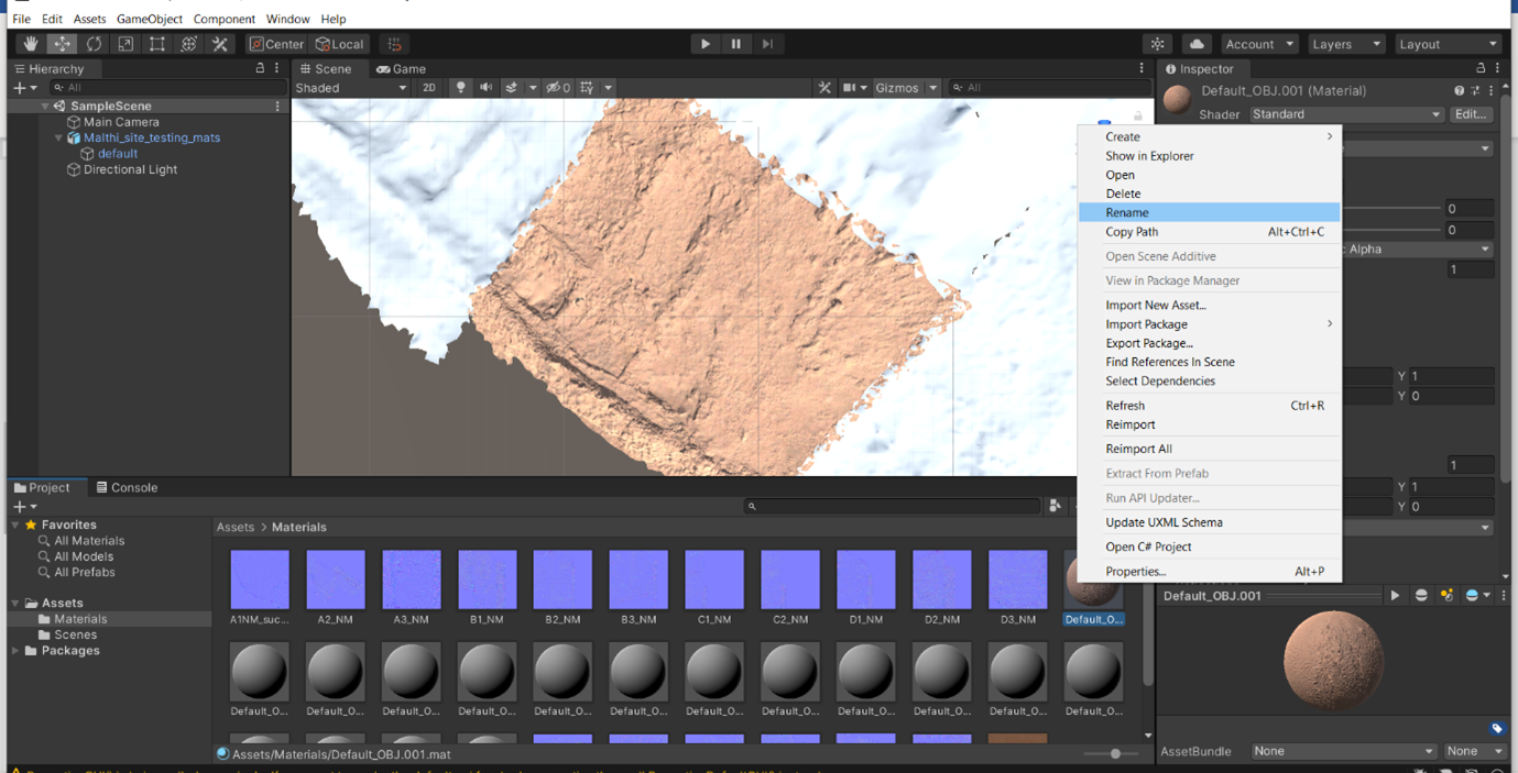
- To make future changes easier, be sure to rename the Material to match its corresponding Normal Map after you have identified it, by right-clicking on the Material in the folder and selecting ‘Rename’. You can then experiment with different settings for each material by adding textures or colour until you get the look you want for your site.
Think and respond: What other details can you add to your reconstruction? What is necessary to address the aims of the project? Other textures? Should the light source in the scene be positioned in a certain direction (where would the sun be above the actual site of Malthi during the morning? The afternoon? The evening?) As you test your experience, what is missing? Do you need to add a bounding box to ensure your users cannot fall into the ‘void’? What about sound?
While this tutorial has introduced you to a few of the basics behind creating a digital walkthrough of your reconstruction of the site of Malthi, there are many other things you would need to consider to create a truly engaging and immersive experience. Because Unity is widely used, there will more than likely be a YouTube video demonstrating how to add whatever functionality you may want to add. However, you may need to reframe your archaeological queries into a more general or videogame-inclined query before pursuing it. For example, if you wanted to add multiple phases of activity to your site, searching for this may not yield too many results. If you instead reframe this as ‘how to allow players to change between Scenes in Unity’, you may find more useful results about triggers or interfaces to incorporate into your project.
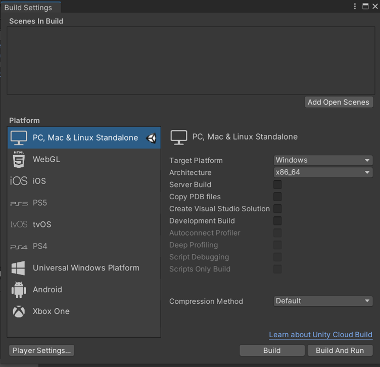
Now, how will your Unity project be made available? There are a number of options for you to explore if you navigate to ‘File>Build Settings’, as shown below. If you want to publish it on a website, you will likely need to publish it for WebGL – Unity provides a tutorial specifically for this here.
Thinking about going further
You may also want to produce an AR or VR application to allow for a fuller exploration of your reconstruction, like the Villa Livia Reloaded gesture-based VR exhibit. These can get quite complex, though the Cine project has produced a series of toolkits to make the construction of these more accessible. Their VR toolkit is available here. Photosphere exhibits, like those hosted at Roundme, can be employed as VR experiences as well, just with hotspot navigation. You could adapt your project in Unity to a VR output, or you could use something completely different, like Aframe. However, whether this would be a useful output for your project will be determined by the project aims, the budget available, the planned use for this application (will you be demonstrating the application at conferences/outreach events? How many headsets do you need to have available?), and the amount of time available to complete it.
Think and respond: Now that you have basic experience with both approaches, given the requirements/parameters of the project set out in Exercise 1, do you think that Sketchfab or Unity would be a better output? Why have you made that choice? What are the benefits of using Sketchfab, despite its limited functionality? What are the benefits of Unity, despite the amount of learning and time it takes to create an engaging experience?
- Ed González-Tennant’s Rosewood Cemetery on Sketchfab: https://sketchfab.com/3d-models/virtual-rosewood-cemetery-3cbb80a2442042818b2759281e9985e8
- Bob Marshall’s Portfolio of 2D Renders: https://www.artstation.com/artwork/48RWl2
- Cine’s Roundme of St Catherine’s Church and Graveyard Reconstruction, Co. Donegal Ireland: https://roundme.com/embed/553737/1812563
- Villa Livia Reloaded: http://www.v-must.net/villa-livia-reloaded
- Open Virtual Worlds:
-
3DHOP: https://www.3dhop.net/index.php Marco Potenziani, Marco Callieri, Matteo Dellepiane, Massimiliano Corsini, Federico Ponchio, and Roberto Scopigno. 2015. 3DHOP. Computers and Graphics. 52, C (November 2015), 129–141. DOI: https://doi.org/10.1016/j.cag.2015.07.001
-
A-frame: https://aframe.io/
-
Europeana Pro: https://pro.europeana.eu/project/v4design
- Share3D: <https://pro.europeana.eu/project/share3d> -
Godot Engine: https://godotengine.org/
-
Sketchfab: https://help.sketchfab.com/hc/en-us/articles/211640363-VR-AR-Editor
Papadopoulos, C. and Schreibman, S. 2019. Towards 3D Scholarly Editions: The Battle of Mount Street Bridge. Digital Humanities Quarterly. 13(1): 31-57. http://www.digitalhumanities.org/dhq/vol/13/1/index.html.
Plaksin, Andrey: https://sketchfab.com/3d-models/the-tomb-of-nefertari-3d-vr35-v0-73-90034cbe58904828a11429395cef9125
Watterson, A, Anderson, J & Baxter, K 2020, Designing Digital Engagements: Approaches to creative practice and adaptable programming for archaeological visualisation. In Proceedings of EVA London 2020. http://www.seriousanimation.com/hillforts/
- Object2Terrain Script download: https://www.mediafire.com/file/3oyvdjcjix2d3iu/Object2Terrain.cs/file
Unity User Manual 2020.3 (https://docs.unity3d.com/Manual/index.html)
- First Person Controller: https://assetstore.unity.com/packages/essentials/starter-assets-first-person-character-controller-196525
- Importing from Blender: https://docs.unity3d.com/530/Documentation/Manual/HOWTO-ImportObjectBlender.html
- Mesh Collider: https://docs.unity3d.com/Manual/class-MeshCollider.html
- Normal Maps: https://docs.unity3d.com/Manual/StandardShaderMaterialParameterNormalMap.html
- Terrain Engine: https://docs.unity.cn/560/Documentation/Manual/script-Terrain.html
- WebGL: https://learn.unity.com/tutorial/how-to-publish-for-webgl
- de Byl, Penny. 2018. “FBX Importing to Unity 2017/2018+ Where did my textures go?” Youtube. Uploaded by Holistic3d, 25 January 2018, https://www.youtube.com/watch?v=xOeodlLTx8g.
- Imphenzia. 2020. “LEARN UNITY - The Most BASIC TUTORIAL I'll Ever Make”. YouTube. Uploaded by Imphenzia, 24 July 2020, https://youtu.be/pwZpJzpE2lQ.