lesson 01 set alt5 for gpio 14/15 #251
Comments
|
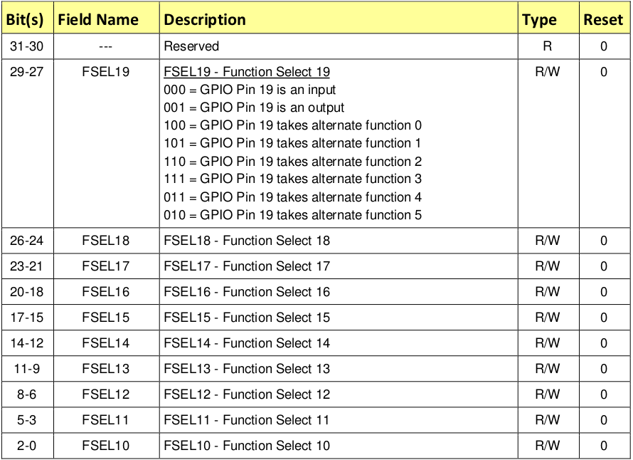
for the GPFSEL1 register, bits 12-14 control gpio 14 and bits 15-17 control gpio 15. (7 << 12) is putting 111 in the bits 12-14 and &= ~ is clearing them, essentially. 2 << 12 is setting bits 12-14 as 010. Same goes for the 15-17 bits. |
|
@rockytriton Thx for your answer. It's more clear for me. I've a last question how we choose 010 and 111 ?
|

|
15th GPIO alt 5 = RXD1. From the table at the top 010 sets alt 5. The 111 is just to mask all 3 bits so we can clear them first before setting the values. selector &= ~(7<<15); That creates a mask with 15 to 17 bits set to 111, then ~ inverts the bits so all bits are set except for 15 to 17, then selector &= that to ensure that bits 15 to 17 are cleared (set to 0) but the remaining bits on selector are left as-is. Now that we clear those 3 bits, we can set the value to 010 by ORing it with this line: selector |= 2<<15; |
|
@rockytriton Okay thank you very much for your explanations :)
|
I'm currently read the first lesson and I can't understand why we use 12 and 15 to speak about 14/15 gpio
The text was updated successfully, but these errors were encountered: