Home
- Hardware - Computer
- Hardware - Connecting RS485 to control panel
- Installing AqualinkD
- Make AqualinkD
- Upgrading AqualinkD to latest release
- AqualinkD Docker container
- Notes on Aqualink PDA only (non RS panels)
- Supported protocols (before you configure)
- AqualinkD service configuration
- AqualinkD serial logging
- AqualinkD WEB UI configuration
- AqualinkD Scheduler
- AqualinkD Manager
- AqualinkD Log
- Common Problems
- Notes on Panel versions & protocols
- RS485 protocol, wiring & adapters
- Apple HomeKit configuration
- Domoticz configuration
- HASSIO configuration
- Meteohub configuration
- Generic configuration (Alexa, Google, Smartthings etc)
- API configuration
- MQTT configuration
Raspberry Pi Zero is the perfect device for this software but any Linux device with a USB connection will also work. AqualinkD comes pre-compiled for Raspberry PI, but all the source is available and designed to be compiled on any Linux based OS with no external dependencies, making it very simple for compiled for any Linux device. Even if you have never compiled anything before. It's been tested on a myriad of different devices, so if your preference is something other than a Raspberry Pi Zero you will be fine as long as it can run Linux.
All Raspberry PI's (except Pi4) are inherently unstable devices to be running 24/7/365 in default Linux configurations. This is due to the way the hardware address the CF card, a power outage will generally cause CF card corruption. Pi 4 have addressed the hardware limitation, more recent version of RaspberryOS have overcome this for all Pi version.
To make this extremely stable installation, my recommendation is to use what is called a "read only root" installation of Linux. Converting Raspbian to this is quite simple but will require some Linux knowledge. There are two methods; one uses overlayfs and if you are not knowledgeable in Linux this is the easiest option. There are a some downsides to this method on a PI, so my preferred method is to simply use tmpfs on it's own without overlayfs ontop, this is easier to setup initially, but will probably require a few custom things to get right as some services will fail. Once you are up and running you should research this topic. My Pi Zero running AqualinkD has been running like this 24/7/365 for over 8 years without one failuer or CF corruption. There are plenty of resources and even some scripts that will do everything for you. Below are two links that explain the process.
Good overlayfs tutorial on PI Forums
I have my own scripts to do this for me, and probably won't ever document or publish them, but thay are very similar to the 2nd link above.
If your hardware supports booting of anything other than a CF card (like the Pi 3), I strongly suggest you use that options with some form of SSD as it's a lot easier then RO Root described above.
You will need a USB2RS485 adapter This one is highly recommended. For more information on adapters and RS485 wiring click here for RS485 overview and adapters.
The adapter connects the computer running AqualinkD to the RS485 interface used by your pool equipment. (If you have an inside controller / keypad mounted on your wall this is usually the best place, if not, the outside control panel is the next best place).
The simplest configuration is to connect the data + and data - from the USB2RS485 adapter to the data + and data - lines of the RS485 interface of any piece of pool equipment. Some USB adapters will have 3,4 or 6 connections, the 3rd is for ground, This can be important or problematic depending on your specific install, and the 4th power should generally not be used a USB2serial adapter. Standard RS485 pool equipment cable is 4 wires, (Data + & - and Power + & Ground -).
The wire colors will depend on your installation, and label colors have changed over the years so it is hard to tell you exactly what colors to connect to. You should get your pool equipment manual and check but below is the most common information.
The control panel will have a 4 post connector at the top right, (some will have 2). This is the RS485 interface. The wire colors will be labeled but not with what they actually do. This is usually (Green, Yellow, Black, Red).
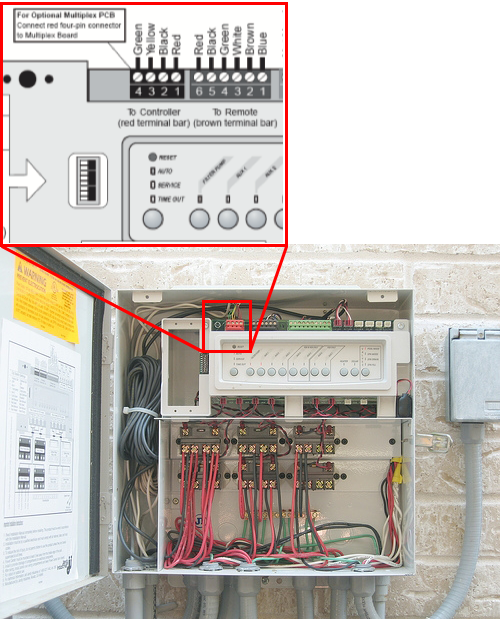
In this example, you want the Yellow & Black wires, (Pin 2 & Pin 3), connect these to your RS4852USB adapter. You can always pick these wires up from any wired control panel inside your house. Pins are usually as follows
| RS Panel | USB Adapter | Description | Connection |
|---|---|---|---|
| Pin #2 Black | RS485 #A | Data + | (Connect #2 to #A) |
| Pin #3 Yellow | RS485 #B | Data - | (Connect #3 to #B) |
###Note on wire. The wire and connections are very critical to getting a clean signal, if you get a lot of "checksum errors" in the logs this is usually due to wiring problems.
Recommended wire is 24AWG twisted pair. Complete info is in below paragraph taken from RS Cable Selection
The RS-422 specification recommends 24AWG twisted pair cable with a shunt capacitance of 16 pF per foot and 100 ohm characteristic impedance. While the RS-485 specification does not specify cabling, these recommendations should be used for RS-485 systems as well.
Connect the USB2RS485 adapter to your RaspberryPI and find out the USB port. Run the below command to make sure the Linux kernel recognizes the adapter.
dmesg | grep usb

This should output something similar to below
...
[    1.643842] usb 1-1: Product: FT232R USB UART
[    1.646974] usb 1-1: Manufacturer: FTDI
[    1.649988] usb 1-1: SerialNumber: A50285BI
.....
[   11.227839] usb 1-1: Detected FT232RL
[   11.414036] usb 1-1: FTDI USB Serial Device converter now attached to ttyUSB0
Notice the last line, that is your device, add /dev/ to it for complete path /dev/ttyUSB0
Check and make sure you are getting something from the USB device.
sudo -s eval 'stty raw -echo < /dev/ttyUSB0; cat -vte /dev/ttyUSB0'
That should give you lots of junk and a few words like below:
^C^@JANDY AquaLinkRSp^P^C^@^P^B^@^A^@^@^S^P^C^@^P^B*^@<^P^C^P^B^H^B^@^@^@^@^@^\^P^C^@^P^B^@^A^@^@^S^P^C^P^B$
^B^@^@^@^@^@^^^P^C^@^P^B^@^A^@^@^S^P^C^@^P^B`^@r^P^C^P^B^H^B^@^@^@^@^@^\^P^C^@^P^B^@^A^@^@^S^P^C^P^B$
^B^@^@^@^@^@^^^P^C^@^P^B^@^A^@^@^S^P^C^@^P^B+^@=^P^C^P^B^H^B^@^@^@^@^@^\^P^C^@^P^B^@^A^@^@^S^P^C^P^B$
^B^@^@^@^@^@^^^P^C^@^P^B^@^A^@^@^S^P^C^@^P^B`^@r^P^C^P^B^H^B^@^@^@^@^@^\^P^C^@^P^B^@^A^@^@^S^P^C^P^B^H^C^@ AIR TEMP 87M-_F  c^P^C^@^P^B^@^A^@^@^S^P^C^P^B$
^B^@^@^@^@^@^^^P^C^@^P^B^@^A^@^@^S^P^C^@^P^B8^@J^P^C^P^B^H^B^@^@^@^@^@^\^P^C^@^P^B^@^A^@^@^S^P^C^P^B$
If you get this far, things are looking good. Go to installing AqualinkD.
If you are using a raspberry PI with Raspbain you can simply use the below to install. Install first time. (This installs a script to your machine, and executes it)
cd ~
curl -s https://raw.githubusercontent.com/sfeakes/AqualinkD/master/extras/aqua.sh -o aqua.sh && chmod 755 aqua.sh && ./aqua.sh release
Once you have run the above there will be a script in your home directory aqua.sh this is what you run from now on to perform upgrades.
~/aqua.sh release      <- Download & install latest AqualinkD stable release.
~/aqua.sh latest       <- Download & install latest AqualinkD version. (development release)
~/aqua.sh force_latest <- Force latest option (don't run any version checks)
~/aqua.sh install      <- Install to local filesystem, (config files will no be overwritten)
~/aqua.sh clean        <- Remove everything, including configuration files
The script downloads the latest version from github AND installs to your filesystem, AND starts / stops deamon.
MAKE SURE TO CONFIGURE AQUALINKD PROPERLY.
- Get a copy of the repo using git.
sudo apt-get install git
cd ~
mkdir software
cd software
git clone https://github.com/sfeakes/AqualinkD.git
-
There is a chance the pre-compiled binary will run.
-
try to run it with :-
sudo ~/software/AqualinkD/release/aqualinkd -d -c ~/software/AqualinkD/release/aqualinkd.conf
-
If it runs but gives you errors, this is good! you can simply install and configure.
sudo ~/software/AqualinkD/release/install.sh- Go to configure section AqualinkD service configuration
-
If it faild to run with some form of error on the binary file you'll need to build a new one. If you do not have a build environment, please see Make section before running the below
cd ~/software/AqualinkD
make clean
make
sudo make install
-
Go to configure section AqualinkD service configuration
-
edit
/etc/aqualinkd.confto your setup -
Test everything works :-
sudo aqualinkd -d -c /etc/aqualinkd.conf- point a web browser to the IP of the box running aqualinkd
-
If all is good enable as service
- sudo
systemctl start aqualinkd
- sudo
Makefile should be self explanatory.
You need to install linux dev tools
sudo apt install build-essential before running make.
As of V2.3.3 AqualinkD uses systemd journal for logging, so to build with everything enabled you need to install libsystemd, the following will install that for you. (This is only needed to build, not run)
sudo apt-get install libsystemd-dev. Alternatively you can disable aqmanager and AqualinkD will use syslog for logging. To do this edit the Makefile and set AQMANAGER to false (from true). Around line 16 AQ_MANAGER = false
If you installed AqualinkD using the above you can upgrade AqualinkD to the latest version with these commands.
cd ~/software/AqualinkD
git pull
sudo ./release/install.sh
First. A container is NOT the prefered way to install AqualinkD, their are none on the usual advantages that a container can provide that relate to AqualinkD, with one exception :- You don't want to run AqualinkD on a device like a Pi.
So if your setup means you can run your RS485 cables to a machine / server, or you want to use a wifi RS485 adapter then this is a good option.
Since AqualinkD needs to be compiled for the target machine archicture and I am not a fan of using emulation inside or for a Docker (Discussion for a different place), if one of the official containers does not suit you target machine architecture, it's recomended you build one. This however does not mean that install is any different from a usual docker deployment, just the fist time the container is run, it will take a little longer as it will be built on and for your host machine.
AqualinkD prebuild containers here are for the following
- ARM64 Any Raspberry Pi running a 64bit OS, Apple M1/2, many other ARM devices. (all will be 64 bit OS)
- AMD64 Any PC running a 64 bit Linux OS.
- Anything else, please build yourself, with tools supplied it's no harder (or even different) than using an pre-build image.
AqualinkD also uses a multistage build progress, using one container to compile/build AqualinkD and a seperate container to deploy AqualinkD. This is because to run AqualinkD you don't need much, but to build it you need a number of tools. So once build you should / can prune your images & volumes to save disk space.
To Deploy the container.
Simply take the docker-compose.yml from the release directory docker-compose.yml and use in the notmal way for your specific setup.
Please make sure to read the details of the file below, and modify to your setup accordingly.
If using the command line:- Create a directory where you want your container to be run from, place the docker-compose.yml into that directory, create a sub-directory called config, then run docker compose up (or) docker-compose up . depending on the version of docker you have installed. This will download all necessary immages, build AqualinkD in a build container, then deploy AqualinkD into a different container, then finally run aqualinkd. Any subsequent times you run docker compose up . it will simply run the AqualinkD container.
mkdir ~/aqualinkd
cd ~/aqualinkd
wget https://raw.githubusercontent.com/sfeakes/AqualinkD/master/docker/docker-compose.yml
mkdir config
sudo docker compose up
Once built and you have run it, you can clean up any of the junk used to build the image with docker image prune
Their are some things to note in the configiration.
Example docker-compose.yml
services:
  aqualinkd:
    image: sfeakes/aqualinkd:latest                                          # <- Comment out if building
    #build:                                                                  # <- Uncomment if building
    #  context: https://github.com/sfeakes/AqualinkD.git#master:docker       # <- Uncomment if building
    #  args:                                                                 # <- Uncomment if building
    #    AQUALINKD_VERSION: v2.3.6 # Make sure to change to correct version  # <- Uncomment if building
    #  tags:                                                                 # <- Uncomment if building
    #    - aqualinkd:v2.3.6                                                  # <- Uncomment if building
    ports:
      - "6171:80"
    volumes:
      - type: bind       # AqualinkD config directory
        source: ./config
        target: /aquadconf
        read_only: false
      - type: bind       # systemd logging
        source: /var/run/systemd/journal/socket
        target: /var/run/systemd/journal/socket
        read_only: false
      - type: bind       # systemd logging
        source: /var/log/journal
        target: /var/log/journal
        read_only: true
      - type: bind       # time
        source: /etc/localtime
        target: /etc/localtime
        read_only: true
      - type: bind       # timezone
        source: /etc/timezone
        target: /etc/timezone
        read_only: true
    devices:             # Map USB
      - "/dev/ttyUSB0:/dev/ttyUSB0"
    logging:
      driver: journald
- You need to pass the USB2RS485 device from your host to the contaner
/dev/ttyUSB0:/dev/ttyUSB0, so modify that as needed. The format is<source>:<target>, so leave the<target>as /dev/ttyUSB0, that way you don't need to modifyaqualinkd.conf, and change<source>to appropiate USB port on your host machine.
- Since you have this on a server, I'll assume port 80 is used, so we are mapping port 6171 on the server to 80 on the container. This means that to get to aqualinkd use
http://<host-ip-address>:6171in a web brower to get to aqualinkd's web ui. Change this to whatever you prefer.
- AqualinkD needs an area for config files, that's'
./configas per above example, but can be any directory you want, this NEEDS to be mapped to/aquaconfinside the container. You don't need to worry about populating any files in this directory, AqualinkD will do this for you the first time it starts.-
aqualinkd.confThis is the main configuration and will need to be edited for your specific panel. -
aqualinkd.scheduleThis is AqualinkD scheduler, do not modify this file. -
config.js(optional) if you want to customise the webui, copy this file from AqualinkD repo, place it here and modify as needed.
-
- Note, this is the only directory / file(s) you need to worry about when changing container versions and such, everything else is throwaway. (Unless you want to backup your container)
- AqualinkD uses systemd journal for logging. Since you shouldn't really put systemd inside a container (at present, I expect this to change in the future). AqualinkD overcoms this by addind a lightweight journal to the container that really only acts as a passthrough to the hosts systemd. The volume mapping lines that contain systemd and journal do just that. These chould not need to be modified.
- /var/run/systemd/journal/socket - is so AqualinkD can write to host journal.
- /var/log/journal - is so AqualinkD can read the journal logs.
- If your system doesn not use systemd, then you can remove these lines, but AaqualinkD managment console (aqmanager) will not have any logging information.
- The
logging: driver: journaldis not for aqualinkD, it's for the container. Since we have journal, let's use it for the docker, that way your logs don't go into oblivion like many docker installs. Simply delete if you don;t want this.
- AqualinkD needs to know the time and time zone you are in, rather than deploying all this inside the container we take it from the host machine, that's what the
localtimeandtimezoneentries are for. Again these should not need to be modified, unless your host stores this someplace else.
- If you need to run a command inside the container before aqualinkd starts, create a file called
aqexec-pre.shand place it in the/aquaconfdirectory described above. An example of this would be to use SOCAT to bind a port to a device for the EW-11 WIFI module. Example of this is hereaqexec-pre.sh
It is recomended that you upgrade your PDA only chip to a RS & PDA chip in your control panel, here is information to do that: Upgrade PDA to RS
PDA only panels are supported in AqualinkD but there are limitations :-
- Can switch devices on/off.
- Can set and read heater setpoints.
- Can set and read SWG information.
- Freeze protect setpoints will depend on your panel version.
- Programming light for different modes is NOT supported; only on/off will work.
- It is very important to label the devices acurately in the AqualinkD configuration as to how they are actually displayed on the Real PDA. This is the only way AqualinkD can do device mapping.
- It will be slow to turn a device on or off (~5 seconds) since the panel has to be put in programming mode.
- While the Jandy control panel can support up to 4 PDA's; it can only support one being awake at any given time. For this reason AqualinkD will go into sleep mode ASAP to let other PDA's work. It will wake every 30 seconds to poll for any device changes, and will wake at any MQTT / WebAPI request, it will action that request and go to sleep again, for these reasons AqualinkD can seem slow to update status. There is a configuration option to turn this sleep mode "off" but it will render a real Jandy PDA inoperable. Leaving the AqualinkD web page open in any browser will stop AqualinkD going to sleep (this is by design).
- Known issues
- If you stop and restart AqualinkD too quickly, there is an issue with initilizing and you may lose devices like Heater setpoints. (Just make sure to stop, wait a few seconds before restarting)
- Putting the control panel into Service mode seems to kill AqualinkD when in PDA mode.
Depending on the version, Jandy control panels can accept input commands on 5 known protocols, these are names after the device they support. AllButton, OneTouch, AqualinkTouch, PDA & RS SerialAdapter. Ignoring PDA (explained below) Each one of these protocols has it's good and bad points, only AqualinkTouch support the full range of panel features but it's also the newest and their for only supported on the fewest(or latest) amount of panels. The one protocol that every panel supports is AllButton, it's also the second fastest protocol (unless you need to program something). So the main AqualinkD code is around this protocol so we can support the widest range of panels. But since the AllButton protocol can be slow in some instances, and it doesn't support Variable Speed Pumps or ChemLink, AqualinkD will make use of other protocols (if you enable and configure them correctly). Hence AqualinkD can also use the other 3 protocols at the same time as using AllButton. The fastest and best protocol by a long way is RS SerialAdapter but this also supports the fewest features. So it's always good to enable rssa_device_id in the configuration to make use of this. Setting & Retreiving Pool/Spa Heater setpoints, retreiving status information on RS12/16 panels will now be instant. Enabeling OneTouch or AqualinkTouch is necessary for VSP or Chemlink support, AqualinkTouch can very signtly speed up setting SWG, time & Color Light modes but unless you have a specific need (ie VSP / Chemlink) they don't give you much. (But this may change in the future). AqualinkTouch is much prefered over OneTouch.
PDA Only panels. At some point, Jandy decided to sell a stripped-down panel (functionality-wise) with a PDA looking device to control it. These panels will ONLY support the PDA protocol, where as RS panels will support all protocols. But this protocol is a real headache and very slow. Strangly enough the OneTouch protocol is clearley the next itteration of the PDA protocol, and far more stable. AqualinkD can be set in PDA only mode, and it will do most things, but it is very slow and error prone compared to the other protocols, and very difficult to fully test in any of the hardware I have available. So this is also not the focus protocol of AqualinkD
If you have more than one wired keypad or PDA only, then go to the Serial Logging section below to find a good device ID.
First stop the service if it's running.
sudo systemctl stop aqualinkd
Edit the configutation file /etc/aqualinkd.conf so it is appropiate for your setup.
The directory where the web files are stored. You can leave this alone on a default installation.
web_directory=/var/www/aqualinkd/
As of Version 2.3.3 AqualinkD has moved to journal logging and AQManager. Please see AqualinkD Log & AqualinkD Manager
Log to file and/or syslog, comment out if you do not want to log to seperate file.
This is usually only used when debugging a problem.
#log_file=/var/log/aqualinkd.log
Log level. [DEBUG_SERIAL, DEBUG, INFO, NOTICE, WARNING, ERROR]
Pick the highest level, and all levels below will be sent to syslog and/or log_file. Your syslog settings may be set to only display messages above a certian level in which case make sure you use the log_file settings to capture everything
log_level=NOTICE
Display any ERROR or Warning messages in web interface.
display_warnings_in_web=false
The socket port that the web daemon listens to
If you change this from 80, remember to update aqualink.service.avahi
socket_port=80
The serial port the daemon access to read the Aqualink RS8.
serial_port=/dev/ttyUSB0
Your RS panel size. ie 4, 6, 8, 12 or 16 relates to RS4, RS6, RS8, RS12 or RS16.
VERY important that you select 12 or 16, if you have either of those size panels.
Also don't think setting a 12 when you have a 8 will give you 4 more accessories to control, it won't the
panel information is needed as different panels use different bits within the RS protocol for status and key presses.
serial_logger will get the panel type string if you don't know it, below are examples.
Must be in format XX-N ???? (XX=RS or PD, N=Circuits, ????=Combo or Only or Dual)
panel_type = RS-8 Combo
#panel_type = PD-8 Combo
#panel_type = RS-16 Combo
#panel_type = RS-2/14 Dual
#panel_type = RS-4 Combo
#panel_type = RS-8 Only
If serial_logger doesn't give you a type string in the format above, you can use the next options to set the specifics. (Number of supported accessories / buttons)
panel_type_size = (6, 8, 10, 12, 14 or 16)
panel_type_combo = (yes or no) (combo panels support BOTH pool & spa)
panel_type_dual = (yes or no) (dual circuit panel)
panel_type_pda = (yes or no)  (PDA panel. only set this if you have to. Panel ONLY supports the PDA protocol)
panel_type_rs = (yes or no)   (RS panel. Panel Supports all protocols)
The id of the Aqualink terminal device. Working RS ID's are 0x0a 0x0b 0x09 0x08 <- 0x08 is usually taken If your panel is a PDA only model, then PDA device ID is 0x60. Other panels support up to 4 PDA's on ID's 0x61, 0x62, 0x63. But you should never need to use those ID's as PDA mode is NOT recomended to use unless you absolutly have no other option.
device_id=0x0a
The ID for rssa_device_id settings, This is for V2.2.1 and above ONLY. If you do NOT have the Jandy RS serial adapter connected to the RS485 bus then this should be used for quicker heater setpoint changes and/or RS16 panels. There is only one known ID at present.
rssa_device_id=0x48
The ID for extended settings, This is for V2.x and above ONLY.
These are to enable Variable Speed Pump information, Chemlink, (one touch macros) & Extended Progamming.
Do not enable this if you don't need it, you'll just waste memory and cpu cycles.
Valid ID's are 0x40, 0x41, 0x42 & 0x43. for OneTouch.
Valid ID's are 0x30, 0x31, 0x32 & 0x33. for Aqualink Touch.
Serial Logging will tell you ID's that are free. Aqualink Touch is prefered over OneTouch if your panel supports both.
extended_device_id=0x41
If you have extended_device_id set, then you can also use that ID for programming some features. This means that you can turn things on/off while AqualinkD is programming certian features. At the moment only heater setpoints & swg boost is on the extended device programming
extended_device_id_programming = yes
Keep the panel time synced with systemtime. Make sure to set systemtime / NTP correctly.
keep_paneltime_synced = yes
Enable AqualinkD scheduler. A version of cron that supports cron.d must be installed for the scheduler to work. If you used the install script and didn't receive any cron warnings, you should be good to go.
enable_scheduler = yes
Putting AqualinkD to sleep when in PDA mode after inactivity: If you have a Jandy PDA then this MUST be set to "yes" as the controller can only support one PDA at any given time. If you don't have a Jandy PDA leave this at "no" and AqualinkD will be a lot quicker. AqualinkD will sleep as it has nothing to do and will wake every 30 seconds to update status. Having Web UI open will force AqualinkD not to sleep.
pda_sleep_mode = yes
Leave this at "No" or commented out. Please see forum for more information, only set to yes when logging information to support new devices. Information will be written to /tmp/RS485.log
debug_RSProtocol_packets = no
Number of milliseconds between sending a reply to control panel.
- Since PDA panels are slower than RS panels it is advised to set this to 4 for PDA panels.
- If you have a Pentair VSP, it's also advisable to set this to 4. Since the Pentaiir VSP uses a different protocol to Jandy, this will allow time for the VSP to send it's alive command.
rs485_frame_delay = 4
Read status information directly from devices on the RS485 bus. AqualinkD will pick up all information from the control panel, but in many cases there is more information available that's not displayed. Use this to enable picking up information from the device directly.
Also note that the panel activly hides information from you. During time when the panel is changing VSP RPM (or the panel looses connection with the pump, which does happen a lot), the panel will actually tell the SWG to go to 0% but will still display a valid % on the jandy keypad. So if you notice this it is perfectly normal and NOT a bug. If you don't like seeing the exact details of the device then don't uncomment the lines below.
swg = Salt Water Generator
ePump = Jandy ePump or ePump AC
vsfPump = Pentair VS,VF,VSF pump
JXi = Jandy JXi heaters
LX = Jandy LX heaters
read_RS485_swg = yes
read_RS485_ePump = yes
read_RS485_vsfPump = yes
read_RS485_JXi = yes
read_RS485_LX = yes
If you have a SWG, set this to "yes". AqualinkD can only detect a SWG if it's actually generating due to the way the protocol works, so after a restart you will not be able to see/access a SWG until the the next time the pump cycles. This will force AqualinkD to setup a SWG on startup.
force_SWG = yes
AqualinkD can take sime time to find heater setpoints (if they exist), This will force the pool & spa heaters to be listed as thermostats vs switches on startup.
force_PS_setpoints = yes
If equiptment is in freeze protect mode some commands like pump_off/spa_on are ignored. You can force these to work by setting the below.
override_freeze_protect = no
AqualinkD can take sime time to find chemical feeder (if panel supports it), This will force the chemical feeder to be listed on startup.
force_chem_feeder = yes
Convert Deg F to Deg C when posting to Domoticz or MQTT. Most automation hobs will only accept temperatures in Deg C, and most Jandy control panels are set for Deg F. So setting these will convert the temperatures for you. Web interface and Web API's will not do any conversion.
convert_mqtt_temp_to_c = yes
convert_dz_temp_to_c = yes
Default is to use pool water temperature as spa water temperature when spa is off (and therefor not able to report water temperature). Enable below to report 0 as the spa temp when spa is off. This is for MQTT cnnections, WEB socket and WEB API always report TEMP_UNKNOWN (-999) allowing the consumer to decide how to report.
report_zero_spa_temp = no
Default is to not report changes to pool temp when the filter pump is off or in spa mode. Enable below to report 0 as the pool temp when the filter pump is off or when in spa mode. This is for MQTT cnnections only, WEB socket and WEB API always report TEMP_UNKNOWN (-999) allowing the consumer to decide how to report.
report_zero_pool_temp = no
MQTT Server connection information If you don't use MQTT, comment all this out, if you use MQTT but not Domoticz MQTT then comment out the two dz topics.
mqtt_address = localhost:1883
mqtt_user = someusername
mqtt_passwd = somepassword
#mqtt_dz_pub_topic = domoticz/in
#mqtt_dz_sub_topic = domoticz/out
mqtt_aq_topic = aqualinkd
#mqtt_hassio_discover_topic = homeassistant
If you have colored lights, then can be programmed by control panel or AqualinkD (if control panel version doesn't support specific light or light mode you want then use AqualinkD to program it, if it does then use the control panel). AqualinkD will be able to set the light mode/color in eitehr configuration
IF YOU WANT AQUALINKD TO PROGRAM THE LIGHT MODES, THEN IT MUST NOT BE CONFIGURED AS A LIGHT/SWITCH IN THE JANDY CONTROL PANEL, IT MUST NOT BE CONFIGURED AS A COLOR LIGHT IN THE JANDY CONTROL PANEL.
All lights work with an on/off pulse to set the mode and advance to the next mode, but the timings of these pulses are different between manufactures. Below are the settings AqualinkD can control, please read your light manufacturer manual and enter the appropiate values.
Note, The light color names / shows are configured in the web interface. /var/www/aqualinkd/config.js -or- <aqualinkd git directory>/web/config.js
If you want AqualinkD to control your color light, then the below are important. If you want the control panel to control the light then these can be ignored. Light programming mode. 0=safe mode. Any number greater than 0 is the seconds to wait between button presses. 0.4 seems to be the minimum, (worked for light modes below 10 presses). 0.6 seems to work about 95% of the time, but modes above 20 presses can be hit or miss. 0 will simply wait for the controler to send the response back before sending the next request. This is equivelent to about 1.2 seconds.
light_programming_mode=0
Light programming assumes that the light needs to be on before sending the first off/on pulse (above setting). If the light is off when a request is made to change "light show", then the below value is used to turn it on for x seconds before it starts programming.
light_programming_initial_on=15
Turn the light off for the below time before start programming pulses.
light_programming_initial_off=12
Everything in this section is for Domoticz ID's. So if it ends with dzidx and you don't use Domoticz, then simply comment it out and move on. Domoticz ID's for sensors, get the ID from your Domoticz Virtual Sensor (described in Domoticz section), and place it here.
air_temp_dzidx=13
pool_water_temp_dzidx=14
spa_water_temp_dzidx=15
SWG_percent_dzidx=151
SWG_PPM_dzidx=153
Try to read labels from Control Panel. (not supported in PDA mode).
use_panel_aux_labels=no
These are all the button labels / options / pump and light configurations you want to use.
Simply change these to your setup, valid options for wach button are :-
None of these are mandatory unless you have PDA or RS16 panel, then _label is mandatory
- RS16 note The RS protocol doesn't support a binary button state for buttons 14 to 17 (AuxB5 to AuxB8), so the only way AqualinkD can get the state is to read text on the labels, so
Button_14_label, Button_15_label, Button_16_label & Button_17_labelMUST be set and to the identical value the control panel has those labels.
button_??_label=Filter Pump  <Label you want to see>
button_??_dzidx=37           <Domoticz IDX>
button_??_pumpID=0x60        <RS485 ID of VSP>
button_??_pumpIndex=1        <Pump index Jandy panel is configured to use>
button_??_lightMode=4        <Color light mode>
If using PDA mode, The Labels below are of the utmost importance, the labels MUST match the labels in the "EQUIPTMENT ON/OFF" menu of the PDA device.
RS 16 Panels have no protocol bit representation for AUXB5 to AUXB8, only text, so as with PDA Those labels MUST match the control panel.
Below is an example of how different Panels map into the buttons.
#
#             |  RS-6 Combo  |  RS-6 Only   | RS-8 Combo   | RS-2/6 Dual  | RS-2/10 Dual |  RS-16 Combo |
#             --------------------------------------------------------------------------------------------
# Button_01   | Filter Pump  | Filter Pump  | Filter Pump  | Filter Pump  | Filter Pump  | Filter Pump  |
# Button_02   | Spa          | Aux_1        | Spa          | Spa          | Spa          | Spa          |
# Button_03   | Aux 1        | Aux 2        | Aux 1        | Aux 1        | Aux 1        | Aux 1        |
# Button_04   | Aux 2        | Aux 3        | Aux 2        | Aux 2        | Aux 2        | Aux 2        |
# Button_05   | Aux 3        | Aux 4        | Aux 3        | Aux 3        | Aux 3        | Aux 3        |
# Button_06   | Aux 4        | Aux 5        | Aux 4        | Aux 4        | Aux 4        | Aux 4        |
# Button_07   | Aux 5        | Temp 1       | Aux 5        | Aux 5        | Aux 5        | Aux 5        |
# Button_08   | Pool Heater  | Temp 2       | Aux 6        | Aux 6        | Aux 6        | Aux 6        |
# Button_09   | Spa Heater   | Solar Heater | Aux 7        | Pool Heater  | Aux B1       | Aux 7        |
# Button_10   | Solar Heater |              | Pool Heater  | Spa Heater   | Aux B2       | Aux B1       |
# Button_11   |              |              | Spa Heater   | Solar Heater | Aux B3       | Aux B2       |
# Button_12   |              |              | Solar Heater |              | Aux B4       | Aux B3       |
# Button_13   |              |              |              |              | Pool Heater  | Aux B4       |
# Button_14   |              |              |              |              | Spa Heater   | Aux B5       |
# Button_15   |              |              |              |              | Solar Heater | Aux B6       |
# Button_16   |              |              |              |              |              | Aux B7       |
# Button_17   |              |              |              |              |              | Aux B8       |
# Button_18   |              |              |              |              |              | Pool Heater  |
# Button_19   |              |              |              |              |              | Spa Heater   |
# Button_20   |              |              |              |              |              | Solar Heater |
Optional, ( button_01_pumpID & button_01_pumpIndex ).
If you have a Variable Speed Pump, then assign the RS485 ID to the button below so RPM/GPH/WATTS are displayed.
Format is button_01_pumpID=0x60
- Pentair pump ID's
- 0x60 to 0x6F (0x60, 0x61 0x62, 0x64, 0x65, 0x66, 0x67, 0x68, 0x69, 0x6A, 0x6B, 0x6C, 0x6D, 0x6E, 0x6F)
- Jandy pump ID's
- 0x78, 0x79, 0x7A, 0x7B
button_01_pumpIndex=1
If you have assigned this pump an index number in your Aqualink control panel, (Between 1 & 4), put it here or VSP, RPM, Primp information to be captured.
Set Colored Lights. All colored light modes are set by cycling or pulsing on/off commands to the light. Jandy control panel can do this for most lights depending on version, or you can get AqualinkD do it in cases your panel doesn't support your specific light or a specific mode you may want. In both cases AqualinkD can set the specific light mode, but you must configure if AqualinkD pulses the on/off or if AqualinkD tells the Control Panle to pulse the on/off. You do this by setting a light mode to a specific button. Light mode 0 is AqualinkD programs the color, anything else is let the control panel set the color.
- You can not mix n match, if your control panel is configured for a color light on a button then you MUST let AqualinkD know that by setting a light mode other than 0, and aqualinkd will not program the light color.
-
button_xx_lightMode=(0=Aqualink program, 1=Jandy, 2=Jandy LED, 3=SAm/SAL, 4=Color Logic, 5=Intellibrite) - If you use mode 0 please make sure to check/set these value (same as V1.x), details are configuration.
- If you use mode 1-6 your control panel HAS to be configured for that same light type (below)
Below is the table of lights & modes that Jandy control panel can configure.
----------------------------------------------------------------------------------------------------------
   | 1=Jandy        | 2=Jandy LED    | 3=SAm/SAL      | 4=Color Logic  | 5=Intellibrite | 6=Dimmer       |
----------------------------------------------------------------------------------------------------------
 1 | Alpine White   | Alpine White   | White          | Voodoo Lounge  | SAm            | 25%            |
 2 | Sky Blue       | Sky Blue       | Light Green    | Blue Sea       | Party          | 50%            |
 3 | Cobalt Blue    | Cobalt Blue    | Green          | Royal Blue     | Romance        | 75%            |
 4 | Caribbean Blue | Caribbean Blue | Cyan           | Afternoon Skies| Caribbean      | 100%           |
 5 | Spring Green   | Spring Green   | Blue           | Emerald        | American       |                |
 6 | Emerald Green  | Emerald Green  | Lavender       | Sangria        | Cal Sunset     |                |
 7 | Emerald Rose   | Emerald Rose   | Magenta        | Cloud White    | Royal          |                |
 8 | Magenta        | Magenta        |                | Twilight       | Blue           |                |
 9 | Violet         | Violet         |                | Tranquility    | Green          |                |
10 | Color Splash   | Slow Splash    |                | Gemstone       | Red            |                |
11 |                | Fast Splash    |                | USA            | White          |                |
12 |                | USA - Show     |                | Mardi Gras     | Magenta        |                |
13 |                | Fat Tuesday    |                | Cool Cabaret   |                |                |
14 |                | Disco Tech     |                |                |                |                |
Labels for standard butons RS-8 Combo panel used as example.
button_01_label=Filter Pump
button_01_pumpID=0x78
button_01_pumpIndex=1

button_02_label=Spa Mode

button_03_label=Cleaner

button_04_label=Waterfall

button_05_label=Spa Blower

button_06_label=Pool Light
#button_05_lightMode=0

button_07_label=Spa Light
#button_05_lightMode=0

button_08_label=NONE

button_09_label=NONE

button_10_label=Pool Heater

button_11_label=Spa Heater

button_12_label=Solar Heater
These are all the button labels you want to use for the web interface and Domoticz virtual sensors. If you have an RS8 Allbutton keypan, most of this is a direct representation of the buttons on that keypad.
Simply change these to your setup, comment out ones that end in _dzidx if you don't use Domoticz.
If using PDA mode, PDA Labels below are of the utmost importance, the PDA labels MUST match the labels in the "EQUIPMENT ON/OFF" menu of the PDA device.
-
button_xx_labelis Mandatory in all configurations -
button_xx_PDA_labelis Mandatory for PDA only, ignore otherwise. -
button_xx_pumpIDis Optional, only for VSP information (details below) -
button_xx_pumpIndexis Optional, only for VSP, MUST be the pump number Jandy control panel has it assigned to (1 to 4) -
button_xx_lightModeis Optional, only for colored lights (details below) -
button_xx_dzidxis Optional, the domoiticz virtual device ID.
button_xx_pumpID, If you have a Variable Speed Pump, then assign the RS485 ID to the button below so RPM/GPH/WATTS are displayed.
Format is button_01_pumpID=0x60. Leave blank/comment out if you don't have a VSP.
If you don't know your VSP ID, you can use Serial Logging to find it.
- Pentair pump ID's are 0x60 to 0x6F so (0x60, 0x61 0x61, 0x62, 0x64, 0x65, 0x66, 0x67, 0x68, 0x69, 0x6A, 0x6B, 0x6C, 0x6D, 0x6E, 0x6F)
- Jandy pump ID's are 0x78, 0x79, 0x7A, 0x7B
button_xx_lightMode, Set the colored light type. If you use 0 (AqualinkD to program) then the control panel MUST be configured for basic light, otherwise if you have colored light, set the type here.
- 0=Aqualink program, 1=Jandy Color, 2=Jandy LED, 3=SAm/SAL, 4=Color Logic, 5=Intellibrite, 6=Jandy Dimmer
Example:-
button_01_label=Filter Pump
#button_01_dzidx=37
button_01_PDA_label=FILTER PUMP
button_01_pumpID=0x60
button_01_pumpIndex=1

button_02_label=Spa Mode
#button_02_dzidx=38
button_02_PDA_label=SPA

button_03_label=Cleaner
#button_03_dzidx=39
button_03_PDA_label=CLEANER

button_04_label=Waterfall
#button_04_dzidx=40
#button_04_PDA_label=AUX2
button_04_pumpID=0x61
button_04_pumpIndex=2

button_05_label=Spa Blower
#button_05_dzidx=41
#button_05_PDA_label=AUX3

button_06_label=Pool Lights
button_06_lightMode=0
#button_06_dzidx=42
#button_06_PDA_label=AUX4

button_07_label=NONE
#button_07_dzidx=43
#button_07_PDA_label=AUX5

button_08_label=NONE
#button_08_dzidx=NONE
#button_08_PDA_label=AUX6

button_09_label=NONE
#button_09_dzidx=NONE
#button_09_PDA_label=AUX7

button_10_label=Pool Heater
#button_10_dzidx=44
button_10_PDA_label=POOL HEAT

button_11_label=Spa Heater
#button_11_dzidx=56
button_11_PDA_label=SPA HEAT

button_12_label=Solar Heater
#button_12_dzidx=NONE
button_12_PDA_label=EXTRA AUX

# There are plenty more buttons to configure on RS12 & RS16 panels.
Once configured, start AqualinkD
sudo systemctl start AqualinkD
The default Device ID of 0x0a will usually be fine for most setups as it's the second all button keypad address, but if you have 2 all button keypads, or something else using this address, you'll need to fine a better address. If two devices share the same address on the RS485 buss, you will have a lot of issues.
Included is a serial loging tool that can let you know all information on the RS485 buss, you can also use this to find a good address.
If you had to make AqualinkD then you will also have to make the serial logging tool.
cd ~/software/AqualinkD
make slog
If you didn't have to make AqualinkD or have already made serial logger, then simply make sure AqualinkD is not running and run the serual logging tool.
Make sure all devices are on before running serial_loger
Some RS485 devices sleep (like PDA & iAqualink), and others don't respond unless they are on and activly doing something (Like SWG & VSP). So make sure all Pumps are on, and all keypads are awake before running serial_logger, that way you'll get an accurate disply of what's on the RS485 bus.
sudo systemctl stop AqualinkD
cd ~/software/AqualinkD
sudo ./release/serial_logger /dev/ttyUSB0
--- example output ---
Notice:  RS Serial: Jandy Control Panel Model   : RS-8 Combo
Notice:  RS Serial: Jandy Control Panel Version : REV T.0.1
Notice: Jandy ID's found
Notice: ID 0x50 is in use  <-- Salt Water Generator (Aquarite mode)
Notice: ID 0x08 is in use  <-- RS Keypad
Notice: ID 0x31 is in use  <-- Aqualink (iAqualink / Touch)
Notice: ID 0x09 is not used  <-- can use for Aqualinkd
Notice: ID 0x0a is not used  <-- can use for Aqualinkd
Notice: ID 0x0b is not used  <-- can use for Aqualinkd
Notice: ID 0x60 is not used  <-- can use for Aqualinkd (PDA mode only)
Notice: ID 0x40 is not used  <-- can use for Aqualinkd (Extended Device ID)
Notice: ID 0x41 is not used  <-- can use for Aqualinkd (Extended Device ID)
Notice: ID 0x42 is not used  <-- can use for Aqualinkd (Extended Device ID)
Notice: ID 0x43 is not used  <-- can use for Aqualinkd (Extended Device ID)
Notice: ID 0x32 is not used  <-- can use for Aqualinkd (Prefered Extended Device ID)
Notice: ID 0x33 is not used  <-- can use for Aqualinkd (Prefered Extended Device ID)

Notice: Pentair ID's found
Notice: ID 0x10 is in use  <-- Pentair Master (Probably Jandy RS Control Panel)
Notice: ID 0x60 is in use  <-- Pentair VSP
Notice: ID 0x20 is in use  <-- Remote wired controller
Notice:
Any address listed with Aqualinkd can be used. This is the device_id address in the config file.
Any address listed with Extended Device ID can be used. This is the extended_device_id address in the config file.
Make note of the Jandy Control Panel Model, you will need that for aqualinkd configuration.
Note, if you have a lot of devices on your RS485 buss then you will need to increase the number of packets to log to find a good ID. -p 2000 is usually enough for busy RS485 buss's.
Command line options for serial_ligger are :-
-d        (print out every packet)
-p 1000   (log 1000 packets, default is 200, 0 will run indefinatly until you press CRTL-C)
-i 0x08   (just log information to and from 0x08, you can pass multiple -i XxXX to log multiple ID's)
-
use http://aqualink.ip.address/ or http://aqualink.ip.address/simple.html to access web UI
-
Both interfaces, edit
<install_dir>/web/config.jsthere are two arrays that can be modified-
devicesList any device you want to see in there (commanent out the ones you don't), the odrer of that list will be the display order of devices.- Note :- By default Solar_Heater and SWG/Percent and are disabeled.
-
light_programIf you have a programable light (and it's configured inaqualinkd.confas a light for AqualinkD to program and not the control panel), then list the light modes here.
-
-
Default interface (not simple.html) has more configuration options
- In
<install_dir>/web/config.js-
var background_url='hk/background.jpg';Change that any valid picture or URL. iehttp://192.168.1.224/snap.jpegfor a camera. -
var background_reload = 10;Change to reload the image ever x seconds, use 0 for static image. -
turn_on_sensortiles=trueTiles that have no state like "Temperature" are shown as off, this wil show them as on. -
show_vsp_gpm=falseVariable Speed Pumps will display the "settable" value, ie RPM or GPM depending on model, you can force all to show RPM with this option. -
var link_spa_and_spa_heater = trueThis will turn on/off the Spa Heater as you turn on/off Spa Mode - There are plenty of colors to change if you like.
- look in
<install_dir>/web/hkhopefully customizing icon are self explanatory. - icons should be around 50x50 pixles and in PNG format.
-
- In
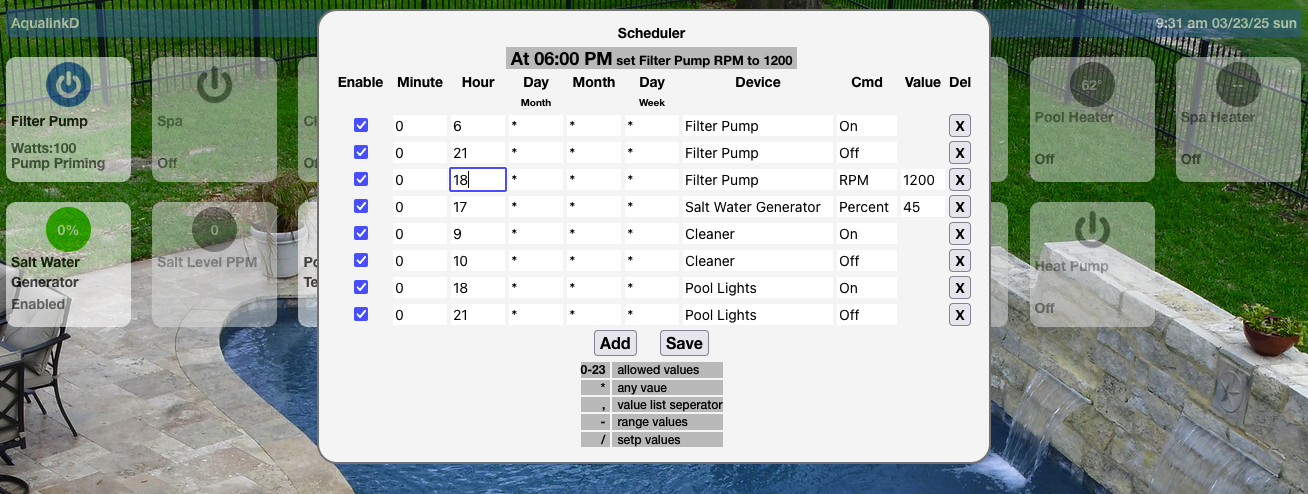
- This does not overide, modify or change any schedules you have programed at the Jandy panel, so it's best to clear all panel schedules.
- To enable AqualnkD scheduler, make sure
enable_scheduler = yesis inaqualinkd.conf - The Scheduler is shown be selecting the time in the top left of the WebUI.
- AqualinkD scheduler depends on cron.d, so a version of cron that supports cron.d must be installed AND enabeled. Look in file
/etc/defaults/cronfor a line like below
# Extra options for cron, see cron(8)
#
# For example, to enable LSB name support in /etc/cron.d/, use
EXTRA_OPTS='-l'
Aqualinkd will write the schedule to /etc/cron.d/aqualinkd
- If you are using read only root file system it will issue a command similar to
mount / -o remount,rwbefore writing andmount / -o remount,roafter writing. - If you are using read only root with something like overlayfs, then AqualinkD will just save the file and expect overloayfs to do the appropiate update to the root filesystem.
cron is an extremely powerful scheduler, that supports a full calendar year and there for you can schedule pool equiptment for seasons. But as such can be a little difficult to understand at first, AqualinkD does provide some help on the options available for each entry in the WebUI and will also show a human readable version or each schedule by clicking on any of the entry cells. Below is an example
Their are also plenty of resources online that explain cron scheduling.
Access AqualinkD Manager using aqmanager.html (example URL below) http://aqualink.ip.address/aqmanager.html
It's purpose is to control and configure AqualinkD without the need of manually editing the configuration files.
At present you can re-start aqualinkd, change logging parameters, down load logs, run serial logger.
Below is an example.
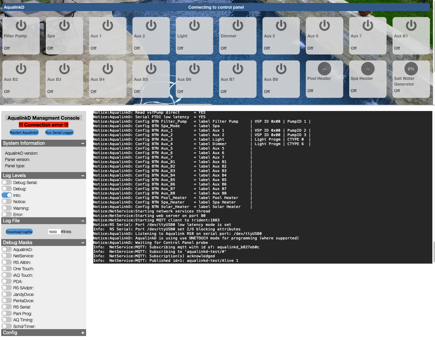
Logging options
- Log Level -> This changes the entire AqualinkD logging to the selected level
- Debug Mask -> This will set a specific subsystem of AqualinkD into debug logging. ie
RS Serialwill just put the RS485 serial comunication into debugging mode.
AqualinkD uses systemd journal for logging (unless compiled without it), to read logs you can use AqualinkD Manager or linux journalcrl
Few examples
- List all aqualinkd messages
sudo journalctl -t aqualinkd - Tail the log
sudo journalctl -t aqualinkd -f - Detail of eash log message
sudo journalctl -f -o json-pretty
Change the level of logging can be done temporarly with AqualinkD Manager or permanently by editing aqualinkd configuration file.
There are several ways to achieve Apple Homekit ingetration, each have their pros and cons.
Both depend on HAP-NodeJS as the base.
-
Homebridgeextends HAP-NodeJS to a generic plugin environment, then there is a AqualinkD plugin for this environment. -
Homebridge UIextends Homebridge with a UI, and automates the install of AqualinkD plugin -
Homekit2MQTTextends HAP-NodeJS to a MQTT only environment, then you simply configure all the devices you want to the AqualinkD MQTT topics.
Homebridge UI seems to have become the defacto standard to use. This describes that install, for any of the other installs please see the Homebridge section of the Legacy wiki
All integrations also depend on a MQTT broker being available.
Head over to Homebridge io and install Homebridge with Homebridge UI following their instructions.
Install a MQTT broker before HomeBridge-AqualinkD, if you already have a MQTT broker, skip the appropiate sections.
Simple go to your local Homebridge UI, Select the Plugins menu (top), Search for AqualinkD, and hit the install button.
Once Installed, hit the configure option and setup the following. Below is an example, simply change to your install.
-
Namekeep this as AqualinkD. -
serverThe machine name or IP of where AqualinkD is rinning -
portThe port AqualinkD is running on (default80unless you changed that in aqualinkd.conf) -
MQTT ServerThe machine name or IP of where your MQTT broker is runing -
MQTT PortThe port MQTT is configured for (1883by default) -
MQTT TopicThe topic for AqualinkD messages (defaultaqualinkdunless you changed that in aqualinkd.conf) -
MQTT UserLeave blank for none -
MQTT PasswordLeave blank for none
You can expand the Exclude Devices and add items to exclude (example Solar Heater)
Once done, save and restart Homebridge, and all your divices will appear in your Apple Home

If you don't already have an MQTT broker Installed, install one. Mosquitto is recomended, this can usually be installed with apt-get
sudo apt-get install mosquitto
Make sure to configure and make sure it starts on boot.
With MQTT
- Enable MQTT in Domoticz, and install a MQTT broker.
- Create a virtual device for each piece of pool equiptment you have, eg Filter Pump, Spa Mode, Pool Light, Cleaner.
- Place the Domoticz IDX for each device in the aqualinkd.conf file under the appropiate button. Then modify each virtual device.
Without MQTT
- Follow generic hub setup.
You can start by using this template. Copy
HASSIO Implimentation.txt
into your config.yaml and modify as needed.
As of AqualinkD 2.3.5 you can use MQTT discovery within Home Assistant / HASSIO.
Simply set the configuration options below in aqualinkd.cfg
By default Home Assistant discovery topic is homeassistant if you have not changed that, just uncomment / edit the below value.
mqtt_hassio_discover_topic = homeassistant
Other configuration options that are highley desired are below.
convert_mqtt_temp_to_c = no
mqtt_timed_update = yes

force_PS_setpoints = yes
force_Frzprotect_setpoints = yes
force_SWG = yes
force_chem_feeder = yes
-
convert_mqtt_temp_to_cMost automation hubs expect temperature in DegC and will then convert to DegF depending on your viewing preferance, Home Assistant is not one of them. So you should turn this off unless you have specifically configured HomeAssistant to receive DegC. Note this means that you can not use both Apple Homekit and HomeAssistant integrations at the same time (unless you configure HomeAssistant to default to DegC)
-
mqtt_timed_updateBy default AqualinkD will only post to MQTT when a device has changed, if HomeAssistant doesn't receive a message within a certian time frame, it marks the entity unavailable, this forces AqualinkD to post updates even if a device hasn't changed.
AqualinkD will take some time to discover certian devices on startup, since it posts to the HomeAssistant discover topic at startup these devices may not be available, So you should force these devices to be available at startup. If you do not have a SWG or Chemical Feeder, then set those to no.
-
force_PS_setpointsis for Heaters (Pool & Spa).
-
force_Frzprotect_setpointsis if you have freeze protect enabled.
-
force_SWGis for Salt Water Enerator.
-
force_chem_feederis for Chemical Feeder.
Once you have set all these accuratly, and start AqualinkD you should see all the devices being populated in Home Assistant. Each time AqualinkD starts, it will post an update, so if you to miss something, somple restart AqualinkD.
AqualinkD will create a Device in Home Assistant, called AqualinkD and assign an area called Pool to this Device, it also ties all Entities (Sensors/Switches/Climate) to this Device. If AqualinkD goes off-line, all these Entities will be 'unavailable', until AqualinkD is back up and running.
If you need to Delete an entity/device, you simply need to delete that MQTT message for that device, their is a great post about that on the Home Assistant forumm. Deleting Auto discovered entity
These messages will be under the topic homeassistant/<type>/aqualinkd/aqualinkd_<unique id>/config
HomeAssistant will automatically add the device name to the entity name (very anoying), this is a design feature. So you will see AqualinkD Filter Pump rather than Filter Pump, I can not change this behaviour from AqualinkD. But there does seem to be a post on how to rename in bulk on their form MQTT Discovery add device name to entity
If you want to log/track air & water temps within MeteoHub, simple configure it to poll the below URL and water & air tempratures will be sent in a format native to MeteoHub.
http://aqualinkd.ip.address:port?command=mhstatus
t0 will be air temp and t1 water temp.
To use. copy the meteohub-aq-plugin.sh script from the extras directory to your meteohub box, edit the script and use your IP address in the line that makes the URL call, below.
wget -O /dev/stdout 'http://your.ip.address.here/?command=mhstatus' 2>/dev/null
In meteohub create a new weatherstation plug-in, plug-in path is the path to the above sctipt, and his save. 2 new sensors should now show up as thermo in the sensor page.
AqualinkD offers 3 ways to connect to it from other devices MQTT, Web API's & Web Sockets.
- MQTT is a realtime pub/sub style event system and will require you to install a MQTT server, like Mosquitto
- WEB API's simple poll based way to get information and request something to be done
- WEB Sockets is realtime and realy only applicable for the WEB UI's included. it's not documented. If someone wants to use this, let me know and I can document it. (or look at the index.html and it should be easy to work out)
All Hubs will use either MQTT or WEB API to counicate with AqualinkD. MQTT is prefered, but it will depend on your setup and how you want to achieve the integration. The MQTT and WEB API defails are detailed in below sections.
All Hubs you will Create a device for each piece of pool equiptment you have, eg Filter Pump, Spa Mode, Pool Light, Cleaner, Water Temperature etc t,brhen configure that device to use either the MQTT or API endpoints listed below to both get the status and set the status for that device.
How you do this will obviously depend on your hub. If your install is not listed in one of the specific sections, once you have configured it, PLEASE post the info in issues section of this site, and I will add it to this page to help others.
You only need to do the configuration in the cloud, since the Smartthings hub itself (Box that you have on your lan) can talk directly to AqualinkD.
Two links that may help
https://docs.smartthings.com/en/latest/cloud-and-lan-connected-device-types-developers-guide/building-lan-connected-device-types/building-the-device-type.html#rest-requests
https://community.smartthings.com/t/generic-camera-device-using-local-connection-new-version-now-available/3269/57
Alexa is a cloud only hub, (please read section below for limitations)
There is a homebridge2alexa project that looks like the best bet (although not tested). So, read the below link, if it's something you want to try, follow the install instructions for Homebridge-AqualinkD above, once running, install this plugin in the same homebridge enfironment. https://github.com/NorthernMan54/homebridge-alexa#readme
Other Alexa options.
Alexa does support direct connection (ie not going through the internet) for the Philips Hue devices. There are lots of projects that simulate Hue devices and allow you to comunicate to your own API's. I have not tried any of them, but the one listed below look like it would be the simpliest to configure (but comes at a cost, see last comment in this section).
https://github.com/armzilla/amazon-echo-ha-bridge
You should simply be able to put the AqualinkD API endpoints in the ha-bridge configutation, like this
{
    "name": "pool pump",
    "deviceType": "switch",
    "offUrl": "http://aqualinkd.ip.address:port?command=Filter_Pump&value=off",
    "onUrl": "http://aqualinkd.ip.address:port?command=Filter_Pump&value=on"
}
Hue devices are limited to on / off and set a %, that should be all that's need for AqualinkD.
The above is java based and depends on some very heavy resources like ElasticSearch, it doesn't seem like the best option for a SBC deployment like a RaspberyPI. The below project has the same functionality and it a lot lighter weight, but looks harder to configure.
https://github.com/bwssytems/ha-bridge
There are also lots of Node Red projects that will do this as well, if you like tinkering that may be a good option as well. Below is an example.
https://flows.nodered.org/node/node-red-contrib-alexa-local
Another interesting option for Alexa is below, it's designed to link Alexa to Homebridge, since AqualinkD can use Homebridge for it's Apple integration, this may be worth investigating further. https://github.com/NorthernMan54/homebridge-alexa If there is any interest I could develop a HomeBridge plugin rather than using HomeKit2MQTT that would connect all this together. Please post in the issues if this is desired.
You will need to way for the cloud server to comunicate directly with AqualinkD, Hubs like Alexa have no real way to comunicate directly to your a device on your LAN other than through the cloud. There are lots of ways to do that, all with their own pro's and cons.
- Google MQTT proxy alexa for a lot of examples.
- Or use a proxy like http://docs.bespoken.tools/en/latest/commands/proxy/
The API has changed segnificantly in V2, V1 is still supported for the moment, but will be removed in the future so plase upgrade to V2.
The V2 API is designed to be identical to the MQTT topics, so if some option you may want is missing from this documentation, please check the MQTT documentation.
Getting status for AqualinkD can be done with either of the following http GET methods.
http://aqualinkd.ip:port/api/devices     <- Detailed information of each device
http://aqualinkd.ip:port/api/status      <- Overview of status of each device.
http://pool.feakes.lan/api/schedules     <- List of schedules
Both return JSON, the both return the overall status of aqualinkd, but /devices will return a lot more information specific to each device. Example command.
curl http://localhost/api/devices
To set a device, you call the device URI with the value you want to change, in either form-post or json format.
Example PUT to turn on the filter pump.
curl -X PUT -d value=1  "localhost/api/Filter_Pump/set"
curl -X PUT -d '{"value":"1"}'  "localhost/api/Filter_Pump/set"
Many devices have other options can be set, you address these in the URI for example, to set the filter pump RPM, you use the below
Example PUT to set the filter pump RPM.
curl -X PUT -d value=2895  "localhost/api/Filter_Pump/RPM/set"
curl -X PUT -d '{"value":"2895"}'  "localhost/api/Filter_Pump/RPM/set"
Below is a list of the URI's that can be used.
On Off commands. (value 1=on, 0=off)
/api/Filter_Pump/set
/api/Spa_Mode/set
/api/Aux_?/set                (<?=1 to 7>)
/api/Aux_B?/set               (<?=1 to 8> RS12 & RS16 panels only)
/api/Pool%20Light/set         (You can also use your Labels, %20 is space in a URI)
/api/Pool_Heater/set
/api/Spa_Heater/set
/api/SWG/Boost/set

Setpoint commands (value = 0 to 105)
/api/Pool_Heater/setpoint/set
/api/Spa_Heater/setpoint/set
/api/SWG/Percent/set
/api/Freeze_Protect/setpoint/set

With rssa_device_id set, you can increase / decrease heater setpoints from their current value
/api/Pool_Heater/setpoint/increment   (number ie 1 or -1)
/api/Spa_Heater/setpoint/increment   (number ie 1 or -1)

Pump RPM/GPM commands. (value RPM or GMP to set)
/api/Filter_Pump/RPM/set
/api/MyPumpLabel/RPM/set

Or you can address the pumps through their #
/api/Pump_?/GPM/set    (? = 1 to 4)
/api/Pump_?/RPM/set    (? = 1 to 4)

Set color light mode. As with on/off you can use Aux_3 or Label
/api/Pool%20Light/color/set   (value will be 1 to 16 - or 0 for current mode)
/api/Pool%20Light/program/set (alias for above)

Timers can be set on anything with on/off
/api/Filter_Pump/timer/set    (value in minutes, will turn device on wait x min turn device off)
You can also open a websocket and receive realtime status updates. The status json will be posted to this socked every time it changes. You can also post json commands over the websocket, but this is NOT recomended. This is reserved for the webUI and as such does change between releases. If you do want realtime updates, MQTT is the prefered method.
curl -i -N -H "Connection: Upgrade" -H "Upgrade: websocket" -H "Host: localhost" -H "Sec-WebSocket-Key: SGVsbG8sIHdvcmxkIQ==" -H "Sec-WebSocket-Version: 13" http://aqualinkd.ip:port
Aqualinkd supports generic MQTT implementations, as well as specific Domoticz one described above.
To enable, simply configure the main topic in aqualinkd.conf.
mqtt_aq_topic = aqualinkd
Then status messages will be posted to the sub-topics listed below, with appropriate information. Each button uses the standard Aqualink RS controller name, so Aux_1 might be your pool light. Note, all Temperatures will be in C, if you have your pool controller configured to F aqualinkd will automatically do the conversion.
Device state information. Devices <Buttons> will be a 1 or 0 for state. 1=on 0=off
aqualinkd/Filter_Pump
aqualinkd/Spa_Mode
aqualinkd/Aux_?                     (<?=1 to 7>)
aqualinkd/Aux_B?                    (<?=1 to 8> RS12 & RS16 panels only)
aqualinkd/Aux_?/delay               (<?=1 to 7>) (0 off, 1 on. If a device has been turned on, but a delayed start is active. Same as flashing LED on keypad)
aqualinkd/Aux_?/timer               (0 off, 1 on. Timer is active)
aqualinkd/Aux_?/timer/duration      (Duration left on timer, in minutes)
aqualinkd/Freeze_Protect            (0 off, 1 on. Freeze protect is activly turning on equiptment)
aqualinkd/Freexe_Protect/enabeled   (0 off, 1 on.)
aqualinkd/Pool_Heater               (0 off, 1 on. Heater is running, heating water)
aqualinkd/Pool_Heater/enabled       (0 off, 1 on. Enabeled means on but not necessarily heating ie, water has reached target temp)
aqualinkd/Spa_Heater                (0 off, 1 on. Heater is running, heating water)
aqualinkd/Spa_Heater/enabled        (0 off, 1 on. enabeled means on not necessarily heating ie, water has reached target temp)
aqualinkd/SWG                       (0 off, 2 on and generating salt.)
aqualinkd/SWG/enabled               (0 off, 2 on but might not generating salt - SWG reported no-flow or equiv.)

Temperatures simply be a number posted to the topic. (float or int)
aqualinkd/Temperature/Air
aqualinkd/Temperature/Pool
aqualinkd/Temperature/Spa
aqualinkd/Pool_Heater/setpoint
aqualinkd/Spa_Heater/setpoint
aqualinkd/Freeze_Protect/setpoint

aqualinkd/display_message           (Any text message to display, either from panel or aqualinkd)

Other Information that's available depending on equiptment
aqualinkd/SWG/Percent               ( SWG Generating %, i.e. 50)
aqualinkd/SWG/PPM                   ( SWG Parts Per Million i.e. 3100)
aqualinkd/SWG/Percent_f             (since we use a homekit thermostat for SWG and use degC as %, we need to pass degF for US phone)
aqualinkd/SWG/fullstatus            (0 on, 1 no flow, 2 low salt, 4 high salt, 8 clean cell, 9 turning off, 16 high current, 32 low volts, 64 low temp, 128 check PCB, 255 off)
aqualinkd/CHEM/pH                   (pH reading if Chemlink installed)
aqualinkd/CHEM/pH_f                 (since we use a homekit temperature for pH and use degC as pH, we need to pass degF for US phone)
aqualinkd/CHEM/ORP                  (ORP reading if Chemlink installed)
aqualinkd/CHEM/ORP_f                (since we use a homekit temperature for pH and use degC as ORP, we need to pass degF for US phone)
aqualinkd/Battery                   (0 Low, 1 Ok. State of the 9v battery in the RS control panel.)
aqualinkd/Service_Mode              (0 off, 1 on, 2 timeout mode)
aqualinkd/Alive                     (Last Will Message, 0 = aqualinkd offline, 1 = aqualinkd alive)

aqualinkd/Filter_Pump/RPM           (VSP RPM Information if available)
aqualinkd/Filter_Pump/Watts         (VSP Watt Information if available)
aqualinkd/Filter_Pump/GPM           (VSP GPM Information if available)
aqualinkd/Aux_?/RPM                 (<?=1 to 7>. If Aux_? is assigned to a VSP pumpID and information is available)
aqualinkd/Aux_?/Watts               (<?=1 to 7>. If Aux_? is assigned to a VSP pumpID and information is available)
aqualinkd/Aux_?/GPM                 (<?=1 to 7>. If Aux_? is assigned to a VSP pumpID and information is available)
To turn something on, or set information, simply add set to the end of the above topics, and post 1 or 0 in the message for a button, or a number for a setpoint. Topics Aqualinkd will act on. (Freeze_Protect does not support changing state, you can only change the setpoint)
aqualinkd/Filter_Pump/set
aqualinkd/Spa_Mode/set
aqualinkd/Aux_1/set
....Aux 2-6.../set
aqualinkd/Aux_7/set
aqualinkd/Pool_Heater/set
aqualinkd/Spa_Heater/set
aqualinkd/Pool_Heater/setpoint/set
aqualinkd/Spa_Heater/setpoint/set
aqualinkd/SWG/Percent/set
aqualinkd/SWG/Percent_f/set          ( Set % as a degF to degC conversion for Homekit)
aqualinkd/Freeze_Protect/setpoint/set

# Change Pump RPM/GPM. RPM or GPM will be dependant on pump config.
aqualinkd/Pump_?/GPM/set      (? = 1 to 4)
aqualinkd/Pump_?/RPM/set      (? = 1 to 4)
aqualinkd/Filter_Pump/RPM/set (can also address pump through label and not #)

# Set color light mode.
aqualinkd/Aux_1/color/set    (value will be 1 to 16 - or 0 for current mode)

# Timers can be set on anything with on/off
aqualinkd/Filter_Pump/timer/set    (value in minutes, will turn device on, wait x min, turn device off)

# With rssa_device_id set, you can increase / decrease heater setpoints from their current value
qualinkd/Pool_Heater/setpoint/increment   (number ie 1 or -1)
aqualinkd/Spa_Heater/setpoint/increment   (number ie 1 or -1)
Example that would turn on the filter pump
aqualinkd/Filter_Pump/set 1
Since AqualinkD supports chemical feeders but many use their own, you can set the pH and ORP values from external sources (rather than RS485), this way you'll get the values in the AqualinkD web UI / Homekit / etc. You set these in the exact same way as the above, either MQTT or HTTP, and you just use the set option
Using curl to do http put
curl -X PUT -d '{"value":"7.5"}'  "localhost/api/CHEM/pH/set"

Using mosquitto_pub to post MQTT message
mosquitto_pub -t aqualinkd/CHEM/pH/set -m 7.2
By far the most common problem is checksum errors, and these are usually due to wiring quality.
If you are having issues of AqualinkD not being responsive to commands or not retrieving correct information from control panel, it is usually due to the quality of data that can be retrieved off the RS485 bus.
Look in the logs, if you see lots of checksum errors this is what's causing it. Checksum errors are caused by one of two things, a conflicting device on the RS485 bus or bad wiring. Use the serial_logger to find out which. If the serial_logger does not show checksum errors, then it's usually a conflicting device that causing the errors, if you see checksum errors in the serial_loger then it's usually a wiring issue. Replacing the USB2RS485 adapter would be the other problem. Go to the AqualinkD serial logging section of this Wiki for more information.
This can happen for multiple reasons. The most common is wiring, the second most common is a VSP pump loosing connection (again sometimes wiring). This has only been reported with Pentair VSP (not Jandy VSP), if the control panel looses connection from the pump it will set the SWG to 0%, then back to it's previous % once the connection is back. I assume it does this to be safe since doesn't know the pump state. The control panel will activly hide this bounce to 0 and back from and devces (like keypads / PDA / iAqualink etc), since AqualinkD reads the SWG messages directly, it shows this bounce. Usually it's no thing to worry about, but their are two config options you can use to hide this. One turn off reading SWG messages directly read_RS485_swg = no, this will make AqualinkD read the % from the control panel, which hides the bounce. Two use the option swg_zero_ignore_count = 20, that will make AqualinkD read 0% for 20 consecutive messages before it shows 0%.
Again the most common cause is wiring. There is one reported case of this happening (that wasn't fixed by wiring) and I think it may be covered in the next section.
RS485 protocol basically works by
- The master (control panel) sending a message with a specific device ID in it.
- The master then expects an acknowledgment reply from that device within a specific time period (~40ms).
- The master then send another message to a different ID (and again expect a reply).
- If the device doesn't reply, it assumes it's dead.
So if a device reply's too late, ie the master has already sent the next message, the device is replying to the wrong message, and this can cause havoc on the control panel.
Pentair protocol has a TO and FROM ID's in each message, I assume to overcome this problem, so if a message is out of order, the master can figure it out. Jandy protocol only has a TO ID in the message, so has no way to tell the message was delivered late.
Ontop of this, when you have Pentair devices (like VSP) on the same bus as Jandy (which is supported), the messages can become embedded in each other and out of sync, This leads to the SWG bouncing to 0% problem mentioned above.
Since RS485 doesn't support read & write at the same time, but USB devices do, the USB2RS485 devices have to manage this some how. Without going into details of how they overcome this, the FTDI converters seem to work the best. These devices also have to buffer the read & write, as does the linux kernel (and device driver) before AqualinkD even receives the message. So with all this buffering that can happen, but with the control panel expecting a reply in under 20ms, that usually doesn't leave much room for error. Usually, AqualinkD will read calculate what to do and write the reply in under 2ms, then with buffering in linux / device it totals about 10ms. I have tested many USB2RS485 converters and some will take 20ms or longer simply to receive the message and post to kernel, and that's before AqualinkD receives it. So in those cases, there can be issues. But if ANYTHING is taking up CPU or other USB bandwidth this can have a dramatic effect on messages being sent in time.
So if you believe you are hitting these problems, there are a few things to check.
- Make sure you have a FTDI USB2RS485 adapter (not clone), little more detail here adapters
- Check the kernel sees it as FTDI adapter, and has loaded the right driver,
- As of AqualinkD 3.2.0f if you see the below message when AqualinkD starts up, you are good. (Or at least the kernal is identifying the adapter as FTDI)
RS Serial: Port /dev/ttyUSB0 low latency mode is set
- If you see either of the below, it's not so good.
Doesn't look like your USB2RS485 device (/dev/ttyUSB0) supports low latency, this might cause problems on a busy RS485 busUnable to set port (/dev/ttyUSB0) to low latency mode
- As of AqualinkD 3.2.0f if you see the below message when AqualinkD starts up, you are good. (Or at least the kernal is identifying the adapter as FTDI)
- Check your Pi hasn't been throttled or seen undervolt. AqualinkD provides a script in the extras directory you can run to check this
- if you see ERROR in any of the below lines, that needs to be fixed.
sudo ./extras/pi_health.sh
CPU temperature: 47.6
CPU Voltage: 1.3500
Undervolt : OK
Undervolt history : OK
Throttled : OK
Throttled history : OK
Frequency Capped : OK
Frequency Capped history : OK
-
Make sure you don't have anything running (or cron jobs) that take considerable CPU or USB bus time, on all pi's before the 4 that can be hard since a ton of stuff is built into the broadcom USB chip. If things happen on a regular bases (like on the hour) this can be the problem.
-
As or AqualinkD 3.2.0f, their are two config option that you can play with. These won't fix the problem, but might help highlight the source of the issue. Both of these should be considered expermental. And it's best not to use both at the same time.
-
prioritize_ack = yesThis will send the Acknoligment before AqualinkD process the message. -
serial_readahead_b4_write = yesThis will read / clean out any kernel buffering before sending, it will simply highlight an issue, it will not fix it. If you see the below message in the logs, AqualinkD was about to send a message after it should have.ERROR on RS485, AqualinkD was too slow in replying to message! (please check for performance issues)
-
The serial_logger will let you know how fast your bus is (this will depend on how many devices you have), but below is an average bus. As you can see, that averages 45ms between each message.
RS Serial: RS485 interface received 600 packets in 28 seconds (~21.43 Msg/Sec)
At present AqualinkD will do everything a RS6/8/12 keypad can do as this is the protocol it mimics. But there are sometimes a few other pieces of equipment on the RS485 bus that are also sending information to the control panel, that the control panel will either not fully support or not support with a RS6 keypad. For instance, Salt Water Generator (SWG) sends far more information to the control panel, than the control panel sends the RS6 keypad about the SWG. In this case, AqualinkD watches these messages so it can have a complete and upto date information about a SWG. At the moment, it's only SWG that AqualinkD can do this for. I'd like to do this for all other devices like Variable Speed Pumps, Chemical Feeders, Heat Pumps etc, but without personally having these devices to play with, I'll need the help of the community, so that's what this section is for.
First of all, don't expect this to happen over night, I'll usually need logs from several different people for each device, and maybe multiple sets. There are 3 main steps to follow
- Set AqualinkD to log the RS485 information.
- Record what you actually did with the equipment.
- Post it to the github discussion board. AqualinkD discussion board
Details on each step
-
Edit /etc/aqualinkd.conf and make sure RS485 debugging is turned on
debug_RSProtocol_packets = yes- MAKE SURE to turn this off once finished (comment out or set to no)
- Each time you start AqualinkD a log file will be created
/tmp/RS485.log. AqualinkD will overwrite this file every time it starts, and for speed will "lazy write" to the file. This means you have to stop AqualinkD for the complete information to be written. So please remember to move/rename it each time you start AqualinkD.
-
Run through a series of small commands recording everything you can.
- In general, you will need to start AqualinkD, change something on the equipment and stop AqualinkD. Keep logs in as many and as small changes as possible. for example, if logging a Variable Speed pump (VSP), the below would be very useful.
- Start AqualinkD, turn VSP on, record what RPM / Watts, stop VSP, stop AqualinkD. Save log and information.
- Start AqualinkD, turn VSP on, record what RPM / Watts, change RPM, record what RPM / Watts, stop VSP, stop AqualinkD. Save log and information.
- Start AqualinkD, turn VSP on, record what RPM / Watts, change RPM (different RPM than before), record what RPM / Watts, stop VSP, stop AqualinkD. Save log and information.
- In general, you will need to start AqualinkD, change something on the equipment and stop AqualinkD. Keep logs in as many and as small changes as possible. for example, if logging a Variable Speed pump (VSP), the below would be very useful.
-
The logs might be quite large, so zip them up and post them to the forum. Please be aware that without detailed information of what you did / what was reported the logs are not very useful. AqualinkD discussion board
In full debug or serial debug mode AqualinkD will spit out a ton of information, most of which is probably not relevant to what you are trying to do. As such, you can set certain parts of AqualinkD into debug mode and leave other parts in normal logging. First understand the normal logging options below, this will set the base level of logging. You ONLY select / uncomment one of these levels.
#log_level=DEBUG_SERIAL
#log_level=DEBUG
#log_level=INFO
#log_level=NOTICE
log_level=WARNING
#log_level=ERROR
Next you can put specific areas of AqualinkD into DEBUG mode, while leaving all others in the mode above. You can select / uncomment MULTIPLE of these.
#debug_log_mask = 1    // AQUA_LOG Aqualink general debug
#debug_log_mask = 2    // NET_LOG network utils debug
#debug_log_mask = 4    // AQRS_LOG AqualinkRS debug (general information fro panel)
#debug_log_mask = 8    // ONET_LOG Onetouch debug
#debug_log_mask = 16   // IAQT_LOG iAqualink debug
#debug_log_mask = 32   // PDA_LOG  PAD debug
#debug_log_mask = 64   // RSSA_LOG RS Serial Adapter debug
#debug_log_mask = 128  // DJAN_LOG Jandy device debug (SWG, VSP, etc)
#debug_log_mask = 256  // DPEN_LOG Pentair debice debug (VSP)
#debug_log_mask = 512  // RSSD_LOG Serial Connection debug
#debug_log_mask = 1024 // PROG_LOG Programming debug
#debug_log_mask = 2048 // DBGT_LOG Debug timing information
#debug_log_mask = 4096 // TIMR_LOG Timer & Scheduler debug
debug_log_mask = 512 // RSSD_LOG Will be like setting SERIAL_DEBUG, but you will only get RS485 messages and not put the rest of AqualinkD in DEBUG mode. If you are interested in a specific RS485 device only, then you can filter the messages further with the below, and is will only print RS485 messages from (and AqualinkD messages to) that specific ID. Only ONE ID is supported.
RSSD_LOG_filter = 0x48
Also don't forget the below options to log all RS485 information. (None of the above-mentioned settings will effect how these setting log).
# All RS485 Information will be written to /tmp/RS485.log & /tmp/RS485_raw.log respectively
debug_RSProtocol_packets = no  // Information will be formatted as AqualinkD decodes the bytes into packets.
debug_RSProtocol_bytes = no    // Raw byte bump of everything read.
AqualinkD supports many protocols the complete list is below. But for referance here are a few things to consider.
- AllButton is required and is the protocol AqualinkD uses for all of it's comunication (unless below options are set in which case it's used for most but not all comunication). This is the
device_idseting- VSP is the only thing not supported with this protocol.
- OneTouch or iAqualinkTouch protocol is required for full VSP support, this is
extended_device_idsetting. If you have this enabeled, then using this protocol to changing time / setpoints / SWG is also slightly quicker than the Allbutton protocol and can be enabeled withextended_device_id_programming=yes.- If your panel supports it that iAqualinkTouch is prefered over OueTouch.
- Serial Adapter protocol is instant in changing heater setpoints, this is
rssa_device_id.- This will also poll the panel for setpoints at regular intervals to keep AqualinkD and Panel in sync. ie AqualinkD expects you to only change setpoints from AqualinkD and no other keypad unless this is enabeled.
- RS16 Panels have 4 status LED's missing and information on these status is missing from all protocols so getting device updates on those 4 devices can be slow, using
rssa_device_idwill speed this up, but it won't be instant like the status of devices upto RS12.
Below is protocols and panel revisions.
# Possible Online       | As Shown in Diagnostics| Possible Unit  | Unit Order*  | Earliest PPD| AqualinkD |
# Devices               | While Online           | Numbers        | Important?   | Revision    | Support   |
#-----------------------|------------------------|----------------|--------------|-------------|------------
# All Button            | CONTROL PANEL          | 1,2,3,4        | No*          | C           | Yes
# AquaLink PC           | CONTROL PANEL 4        | 4              | Yes**        | C           | No
# OneTouch              | ONETOUCH               | 1,2,3,4        | No           | I           | Yes
# Wireless OneTouch***  | ONETOUCH               | 1,2,3,4        | No           | I           | (as above)
# Serial Adapter        | SERIAL ADAPTR          | 1,2,           | No           | I           | Yes
# PHASTLink Serl Adptr  | SERIAL ADAPTR          | 1,2            | No           | I           | (as above)
# SpaLink® RS           | SPALINK                | 1,2,3          | No           | G           | No
# Dual Spa Side Switch  | SPA SW BOARD           | ----           | ----         | C           | No
# iAqualink Touch       |                        | 1,2,3,4        | No           | R           | Yes
# Tele-Link®            | TELELINK 1             | 1              | ----         | C           | No
# Auxiliary Power Center| REMOTE PWRCNTR         | 1,2,3          | Yes          |             | No
# LX Heater             | LX HTR                 | 1,2            | Yes          | H           | No
# AquaPure® Chlorinator | AquaPure               | 1              | ----         | I           | Yes (read only)
# AquaPalmTM            | AQUAPALM               | 1              | ----         | MMM         | Yes (Beta)
# RS InterLink          |                        | ----           | ----         | N           | No
# LXi Heater            | LXi HTR                | 1,2            | Yes          | N           | No
# Jandy VSP (ePump)     | Jandy ePUMP            | 1,2,3,4        | No           | ??          | No
# Pentair VSP (VF/VS)   | Intelliflo VS or VF    | 16 total       | No           | ??          | Yes (read only)
#

* Unit order. Yes means that the unit number must be set correctly or the device will not work properly. The unit number is set by slide-on jumpers, a DIP switch, or a wire, depending on the type of device.
**If an AquaLink PC is online, there must NOT be an All Button or OneTouch jumpered, as in number 4.
***Wireless OneTouch is shown as any other OneTouch. Its jumpers must not match the jumpers in any other OneTouch.
Below are the configuration variables along with valid ID's, the serial_logger tool can provide information about ones that are inuse or free
# AqualinkD.conf      | RS485 Protocol       | RS485 ID
# setting             |                      |
#---------------------|----------------------|------------------------
#  device_id          | All Button ID's      | 0x0a, 0x0b, 0x09, 0x08
#  extended_device_id | OneTouch ID's        | 0x40, 0x41, 0x42, 0x43
#  rssa_device_id     | Serial Adapter ID's  | 0x48, ?x??
#  extended_device_id | iAqualink Touch ID's | 0x30, 0x31, 0x32, 0x33
#  device_id          | PDA ID's             | 0x60
#  force_SWG = yes    | AquaPure® Chlorinator| 0x50
#  button_??_pumpID   | Jandy VSP ID's       | 0x78, 0x79, 0x7A, 0x7B
#  button_??_pumpID   | Pentair VSP ID's     | 0x60 to 0x6F
All pool equiptment uses a half duplex RS485 protocol to comunicate between Control Panel, Keypads and inteligent Devices like Salt Water Generators, Variable Speed Pumps, Chemical feeders & some heaters.
There are a few main problems areas that you should have a basic understanding of, that can effect the performance.
- RS485 Wiring and Termination (The majority of issues new people have are here)
- RS485 USB Adapters and how they actually work in reguard to Pool equiptment. (this becomes very important on busy RS485 bus)
Below is a basic diagram of RS485 bus
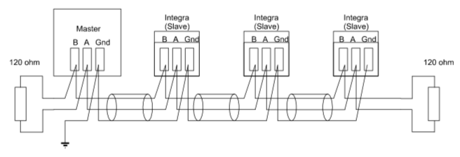
As you can see, each device is connected to 3 wires (Data+, Data- & Ground), and there is a termination resistor at each end of the wiring (or bus).
The ground connection is their so the adapter has a referance point for the voltages in Data+ & Data-, and there is some level of circuit protection.
The termination resistors are their to prodide clear signals and stop reflection. Here is a detailed article on that
With referance to the wiring above, many USB2RS485 adapters don't have the ground wire they only have 2 (data+ & -), and when they do they are not always correctly protected and that can cause a problem in the RS485 bus, like a nearby lightning strike, to kill the adapter (and sometimes the computer it's connected to). But in most cases the lack or ground will not cause you any major problems. But if you are having RS485 issues this is the first point to check. Most (but not all) Pool equiptment has built in termination that can't be changed. Most cheap USB2RS485 adapters are also terminated internally. So this means if you blindly connect everything together you'll end up with too many terminations on the RS485 bus and that will also cause you problems.
The jandy RS485 bus will have aproximatly 20~30 messages a second when not much is going on, and will goes up from their depending on what devices are on the bus and how they are interacting with the control panel. AqualinkD (along with all devices) will read each message and make a quick decision, (ignore message, reply to message, act on message and reply). Since this specific RS485 implimentation is half-duplex, this means that while the interface needs to both read and write, it can't actually do both at the same time. This means that something needs to flip a switch in the adapter to set it to read OR write mode. Most / all adapters do this automatically by making a guess depending on TX/RX pin states. Ontop of that USB chips and/or OS Kernel will also cache messages, and the Jandy protocol only has a message TO id, not a message FROM id (so message order is highley important). So when you have ~30 messages a second on the bus that need to be read and about 0.1 of a second to reply, any form of read / write delay can cause havoc. The combination on these problems togeter means that USB2RS485 adapter choice is important. This is also more important for a Jandy control panel vs a Pentair since the Pentair RS485 protocol has a FROM id, so message order is not as important.
On top of the above, the Raspberry Pi hardware (all version before Pi4) uses the same chip for USB/Network and a whole host of other things, making it IO bound. Can make for a whole host of issues when you consider AqualinkD's main putpost is to interface RS485 with network. While the Raspberry Pi4 has seperated network & USB chips, currently this doesn't help much as the USB interface of the Pre-Pi4's has had a huge developer influance to make it as solid as it currently is, and the Pi4 simply hasn't had that maturity yet.
In writing all of the above, this doesn't mean that you'll get problems with using Pi / USB2RS485 adapter & AqualinkD, it run's exceptionally happily 24/7/365 for 95~97% of the users and installs out their. But if you do run into issues please consider the above, and read the below suggestions.
Most USB2RS485 adapters use a FTDI (or clone) chipset for the USB side, (USB to UART) and a variaty of RS485 chips for the other side (UART to RS458), or in the case of FTDI FT232R chipset it can handle both.
Counterfeit FT232RL chips are quite common, especially on inexpensive hardware, and most simply do no have the realibility of FTDI. More on fake FT232
So in short, it's best to get an USB2RS485 that will give you the option to ground and the choice to terminate or not. Some adapters do this by the way of allowing you to solder a resistor to the board, and others (as in below link) you can simply connect 2 wires together.
Official FTDI USB-RS485-WE-1800-BT Prefered Adapter
OctagonStar USB to TTL/RS485 Serial Converter Adapter Solid choice, but no termination options
Please note, these recomendations are the official FTDI USB2RS485 adapters, there are many others that use the official FTDI chipset.
Official FTDI adapters.
https://www.ftdichip.com/Products/Cables/USBRS485.htm
As stated previously, Pi's can be very IO bound since they all (except Pi4) use the same chip for network & USB and getting the fastest/latest/greatest Pi doesn't really help this. But correct power does, if you have a bad PSU (like cheap wall USB charger) they usually can't keep up with the Pi, and the Pi will start to underclock iteself due to undervolt situations. AqualinkD has a quick and dirty bash script to test if this is the case, simply run ./extras/pi_health.sh as root from the aqualinkd download directory and if you see any errors in undervolt/throttled/frequency cap (or their history), you need to change your PSU.
These two items are everything you need to get started.
CanaKit Raspberry Pi Zero W (Wireless) Complete Starter Kit - 16 GB Edition
FTDI USB-RS485-WE-1800-BT Cable, USB to RS485 Serial, 1.8M, Wire END
You can also power the Pi zero off the RS485 wiring. The below (with some soldering) is the perfect PSU for that
This allows you to hide eveything (Pi / PSU / USB2RS485 adapter) inside a Jandy Keypad (Details to come)