3V3A current draw #48
Comments
|
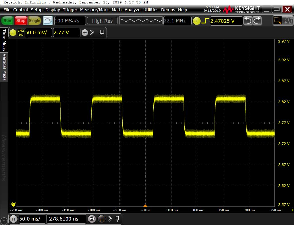
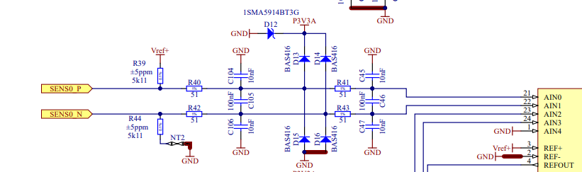
This is the junction between R39 and R40 (i.e. the high side of the thermistor input) Voltage change is approx 100mVpk-pk so current is about 20uA pk-pk. So, this appears to be the sampling current. ADC ref buffers should be enabled. That's out of spec |
|
@gkasprow why is there a 3V3 Zener on the 3V3 rail?
|

|
Yes, removing that diode fixes this |
|
But, we still see 100mV on each ADC input |
|
The sampling issues were a bug in the firmware (setup register bits not correct, so input buffers weren't enabled) cc @astro |
|
The diode was used just in case when somebody connects, let's say 12V to the sensor input. In such a case, R40/R42/R46/R48 would be damaged, not ADC. We should replace it with 3.6V one. |
|
There are 10nF capacitors at the ADC inputs, so it cannot be caused by sampling current |
Sounds good! Just something that doesn't conduct more than a few mA at 3V3!
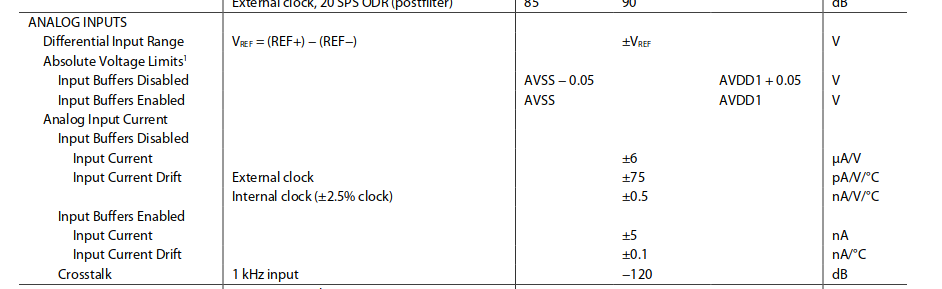
Look at the time scales involved. It's a DC change in the input level that occurs when the inputs are connected to the internal mux. The specification I posted above is 6uA/V (differential inputs) which gives 20uA for a few V differential. So, this is within spec. Just a fw bug that meant that the buffers weren't correctly enabled. |
|
D12 replaced with 1SMA5914BT3G |
|
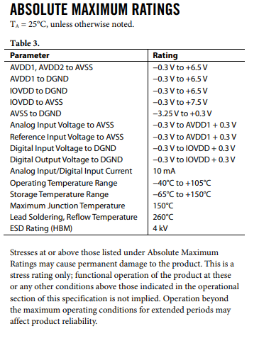
@gkasprow 1SMA5914BT3G is a 3.42V min diode, which still seems a bit low. Can you remind me what the intention of D12 is? Is it to protect the ADC? If so, why not use a 5V Zener (see the ADC abs max ratings below)? In the current hardware, Vref is still ~3.1V which is a bit low (not low enough to cause major issues I think, but lower than we would like).
|
|
Yes, it was to protect the ADC in case of shorting the inputs to 5V |
You mean if the ADC inputs accidentally get shorted to the TEC driver? Unless I'm mis-reading the ADC abs max ratings, this wouldn't be destructive to the ADC. But, maybe you're worried about the higher IO voltage damaging the microprocessor? |
|
It would be destructive to 51OHm resistors because ADC inputs are bypassed by protection diodes. DAC has a dedicated LDO. |
|
U can measure the voltage drop on R35 and see if it is still an issue. We can use a slightly higher voltage diode, but note that if one shorts input to let's say 12V, a lot of current will flow through it and may exceed 6.5V on ADC |
I don't follow you...The Zener doesn't help to protect the 51 Ohm resistors at present...
We should be clear about our goals here... There are lots of places in Sinara where it's easy to cause damage. e.g. connecting a clock input to a 5V TTL will generally do the trick. I don't think it's reasonably possible to protect against that kind of thing so we have to assume a certain level of competence from users. Protecting the ADC inputs from 5V seems like a good idea to me because mis-wiring that connector and accidentally connecting an ADC input to the TEC driver is a relatively easy mistake to make (not that easy given the pin locations but I can see it happening). So, if we can make the system robust to 5V being applied to the ADC then let's do it. However, I do not see any obvious mechanism for 12V getting onto the ADC inputs, so I don't think we should even try to protect against that (and, to do so we'd have to add current limiting resistors in the input path so we'd need to think about noise, offsets etc before doing that).... |
|
@gkasprow without the Zener didoe, what happens if a user applies 5V to the sensor input? As far as I can tell, the ESD diodes will cause the ADC 3V3 rail to increase to close to 5V. That will not be destructive to the ADC. However, it will lead to the ADC digital output logic level going to 5V. Since the microprocessor is powered from 3V3 I assume that will be destructive (but correct me if I'm wrong) or do you think the resistors currently in place will be sufficient for current limiting. My guess is that it will be hard to find a Zener with a low enough leakage current at 3V3 to avoid causing annoying sag in that supply rail, but still low enough voltage to keep the microprocessor within spec for 5V applied to the ADC input. Maybe a better path forwards is to make sure we have current limiting resistors to protect the microprocessor? |
|
4v diode (1SMA5916BT3G) would do the job |
|
works for me... |
|
@astro measured 1.75V across R35, meaning the LDO input voltage is only 3.25V. The LDO output is ~3.0V. Let's go to a 4V diode. |
|
And with the diode removed, the drop is much lower? |
|
That was my observation in the previous hardware revision (which was the same other than the diode)... |
|
Now the voltage drop on R37 is 38mV with TVS installed and the same value with TVS removed, so the current TVS model seem to work fine |
? Did you measure that on hardware? @astro reported 1.75V across R35... |
|
Yes, but I measured it on v2.0 HW. It has a 1SMA5914BT3G diode (814B marking) |
|
in my case it is 1.66V on R35 with diode assembled |
R37 is not relevant for this.
That's about consistent with @astro's findings and suggests that the diode is a problem here. |
|
..and 60mV with diode removed. Sorry, I was measuring on the wrong resistor. Diode current does not pass via R37 |
|
okay, thanks for confirming. Let's verify with the other diode you suggested and check that the voltage drop is acceptable. |
|
I will order 1SMA5916BT3G and 1SMA5915BT3G and see which one works. |
|
with 1SMA5915BT3G i measure 0.76V, |
|
@gkasprow the 1SMA5916BT3G looks like it should be sufficient to prevent damage to the microprocessor. What do you think? |
|
I think so. |
|
fixed |
Input voltage on R35 is 5V0 as expected, output voltage is 2.938V suggest current draw is 62mA, which is more than an order of magnitude more than expected...
The text was updated successfully, but these errors were encountered: