These jumpers configure Arduino Due pins used on the HackEEG shield. For commonly-used settings, see Typical Configuration.
For ADS1299 pin definitions, refer to ADS1299 datasheet.
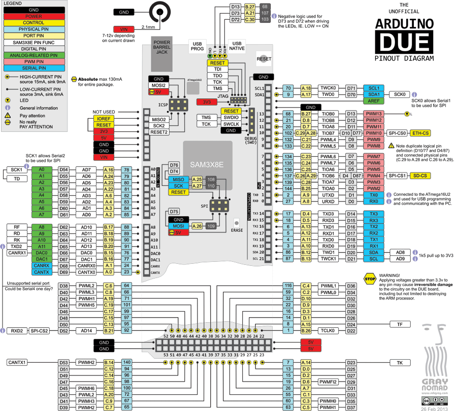
For Arduino Due pin definitions, refer to the Arduino Due pinout diagram, the Arduino Due reference, and the SAM3X8E datasheet.
If you change these jumpers, you must also change the pin definitions in your driver files. For the ads129x_tools driver, this is in the file adsCommand.h
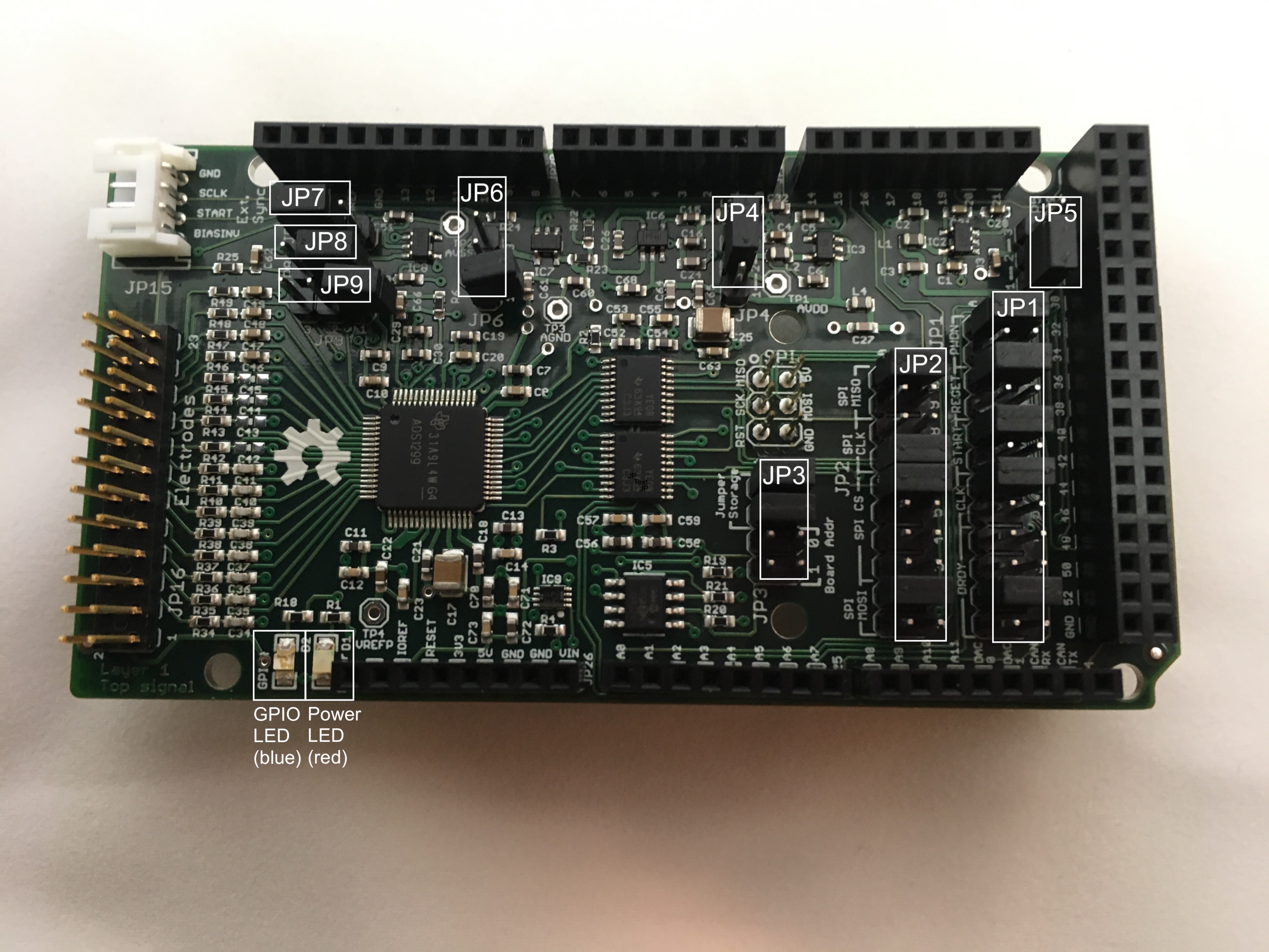
This diagram shows the locations of all the configuration jumpers:
These pins select which ADS1299 pins are connected to which Arduino Due pins. Bridging one pair of jumpers connects the pins together. This enables a stack of shields to use different Arduino Due pins if needed, for instance to connect two HackEEG shields to the native SPI, and two to the USART1 SPI, or to use different Arduino Due PIO pins to control the ADS1299.
For each named signal, you must set exactly one jumper.
| Signal | Jumper # | Arduino pin |
|---|---|---|
DRDY |
1 | D24 |
DRDY |
2 | D25 |
DRDY |
3 | D26 |
DRDY |
4 | D27 |
CLK |
5 | D30 |
CLK |
6 | D31 |
START |
7 | D61 |
START |
8 | D59 |
RESET |
9 | D46 |
RESET |
10 | D47 |
PWDN |
11 | D32 |
PWDN |
12 | D33 |
| Signal | Port | Jumper # | Arduino pin |
|---|---|---|---|
SPI MOSI |
Native | 1 | SPI4 |
SPI MOSI |
USART1 | 2 | D16 |
SPI CS |
Chip Select | 3 | D23 |
SPI CS |
Chip Select | 4 | D52 |
SPI CS |
Chip Select | 5 | D10 |
SPI CS |
Chip Select | 6 | D4 |
SPI SCL |
Native | 7 | SPI3 |
SPI SCL |
USART1 | 8 | A0 |
SPI MISO |
Native | 9 | SPI1 |
SPI MISO |
USART1 | 10 | D17 |
These pins are hard-wired and cannot be configured.
| Signal | Arduino pin |
|---|---|
CLKSEL |
D48 |
| BOARD LED | ADS1299 GPIO4 |
These pins set the 24AA256 I2S EEPROM address 0-3 in binary – they are not connected to Arduino Due pins. The pins are shared with the ADS1299 GPIO, and so can also used as the board address and read via the ADS1299. If not using them as jumpers, external devices can be connected to the header to provide access to the ADS1299 GPIO pins; this usage generally will conflict with using the I2S EEPROM.
| Jumper # | Function |
|---|---|
| 0 | ADS1299 GPIO0 |
| 1 | ADS1299 GPIO1 |
These jumpers configure the instrumentation power supplies that supply the reference voltages for the ADS1299. You can set the ADS1299 to measure voltages in the 0–5V range (unipolar) or in the -2.5V – +2.5V range (bipolar). Bipolar is most commonly used for human or mammal subjects. You must bridge exactly one set of pins on each jumper.
| Pins | Function |
|---|---|
| 1-2 | Sets AVDD to 5V |
| 2-3 | Sets AVDD to 2.5V |
| Pins | Function |
|---|---|
| 1-2 | Sets AVSS to -2.5V |
| 2-3 | Sets AVDD to GROUND |
| Mode Name | ADS1299 Voltage Range | JP4 Pins | JP5 Pins |
|---|---|---|---|
| Unipolar | 0–5V | 1-2 | 2-3 |
| Bipolar | -2.5V – +2.5V | 2-3 | 1-2 |
| Pins | Function |
|---|---|
| 1-2 | Routes SRB1 to BIAS_ELEC on the electrode connector via a 5K resistor |
| 2-3 | Routes a noise source to SRB1 |
| Unconnected | Disconnects BIAS from SRB1 – use in conjunction with JP7/JP8 REF_ELEC functions |
Setting pins 2-3 can be used to test channel noise performance. See section 8.3 of the TI EEG Front-End Demonstration Kit manual. In this mode, BIAS_ELEC and REF_ELEC on the electrode connector need to be connected with a cable, since there is no jumper to do so on the HackEEG board.
| Pins | Function |
|---|---|
| 1-2 | Routes SRB1 to REF_ELEC on the electrode connector via a 5K resistor |
| 2-3 | Routes SRB2 to SRB1 via an opamp |
| Pins | Function |
|---|---|
| 1-2 | Routes REF_ELEC on the electrode connector to the opamp input via a 5K resistor |
| 2-3 | Routes SRB2 to the opamp input |
| Pins | Function |
|---|---|
| 1-2 | Routes BIASOUT to BIAS_ELEC on the electrode connector via a 5K resistor |
| 2-3 | Routes BIASOUT to BIASIN |
| Unconnected | Leaves BIASOUT, BIASIN, and BIAS_ELEC unconnected |