Skip to content
New issue

Have a question about this project? Sign up for a free GitHub account to open an issue and contact its maintainers and the community.

By clicking “Sign up for GitHub”, you agree to our terms of service and privacy statement. We’ll occasionally send you account related emails.

Already on GitHub? Sign in to your account

Add Yeelight YLXD50YL (yeelink.light.ceiling20) support #19

Closed
chris-nite opened this issue Aug 26, 2021 · 19 comments
Closed

Add Yeelight YLXD50YL (yeelink.light.ceiling20) support #19

chris-nite opened this issue Aug 26, 2021 · 19 comments

Comments

@chris-nite
Copy link

chris-nite commented Aug 26, 2021

Hello @syssi ,
thanks again for your great support. As my meteorite lamp is running smoothly since i've upgraded to esphome, i now would like to address my struggling Ceiling Lamp Yeelight YLXD50YL (yeelight ceiling lamp 20), as it is almost always unavailable in HA, as well as there are problems using my CW-LEDs.
This Lamp got a combined Lumen output of 7200lm, as well as a color-LED-Stripe facing to the ceiling.
So far it seems no one have documented anything about this lamp yet, so i teared it apart to see, what i'm working with:

It seems to use a ESP-WROOM-32D Controller on a small WIFI CTRL-Board (VZ6REV 0.1), which fortunately can be removed from the mainboard. The provided PINs allow to directly mount a cable to 3.3V, GND, ADC1, STA.
There are little testpoints from TP1 to TP5.
So far i was unable to find any TX/RX-PINs, so i guess they're hidden in two of these TP, as well as GND0.

I assume as soon as we now, which of those points are important for flashing, it's only a matter of time to get esphome on it.

Do you got hints or any documentation about this Controller @syssi to get started with an USB UART-TTL-Adapter? How is it possible to find out those missing PINs necessary for a flash?

Thanks in advance and best regards.
Chris

@syssi
Copy link
Owner

syssi commented Aug 26, 2021

I try to provide some steps to get the job done:

  1. Lookup the pinout of the ESP32-WROOM-32D. You want to know the position of GPIO0, RXD0 and TXD0. If you are good in soldering you could connect the wires to these pins directly. I recommend to trace the test points (step 2).
  2. Use a multimeter to find a 0 ohm connection between GPIO0, RXD0 and TXD0 and the corresponding TP.
  3. Use a multimeter to find ~0 ohm connections between the ESP32 pins and R, G, B, C, W, STA. We want to know the GPIOs attached to the pin header of the ESP32 daughter board.
  4. Do you know the purpose of the RAD pin?

Ping me if your done. I will provide some more steps. It should be possible to boot the ESP32 without being attached to the lamp (external powered) and play around with the OEM firmware. Use your multimeter to measure the voltag between GPIO and GND. If it's a PWM pin you will be able to drive the voltage between some limits (by controlling the brightness of the lamp f.e.). I assume you can measure 0V between STA and GND if the device is turned off. If you turn the lamp on you should measure ~3.3V. Try to document everything. :-)

@syssi
Copy link
Owner

syssi commented Aug 26, 2021

This is the pinout I'm talking about: https://dl.espressif.com/dl/schematics/pictures/esp32-wroom-32d-front-back.jpg
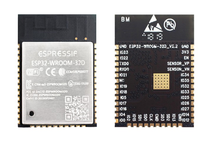
@chris-nite
Copy link
Author

chris-nite commented Aug 26, 2021

Thanks again Sebastian!
I tried to measure all the testpoints, as well as the ESP32 GPIO-PINs.
My multimeter interestingly always showed 100ohm resistance between the (hopefully correct points), when measured between the ESP32 pins and the Testpoints/PIN on the mainboard (it's a Peaktech 3445). I never got 0ohm measurements whatsoever on any of those connections. 100 ohms were the lowest values and only on one of the PINs present while testing. The rest of the pins showed very high ohm-values, so i guess the 100 ohm ones are the right ones. Any idea about this?

Anyway, here are my results:

  • RX --> Testpoint 4
  • TX --> Testpoint 5
  • GND0 --> Testpoint 3
  • Red --> IO33
  • Green --> IO26
  • Blue --> IO27
  • ADC1 --> Sensor_VP
  • STA --> IO22
  • Cold --> IO21
  • Warm --> IO19
  • M1C --> IO16
  • RAD --> high Ohm resistances on all pins (unfortunately i don't know for what this is....)

I didn't try to solder the contacts yet, as the testpoints are amazingly small and i'm not sure, if i got the right solderiron-tips.
Can you please provide me the next steps?

@syssi
Copy link
Owner

syssi commented Aug 26, 2021

  1. Connect RXD, TXD and GND to your TTL adapter.
  2. Power the detached ESP32 board externally by connecting 3.3V + GND. Don't use the 3.3V from the TTL adapter. The adapter doesn't provide enough current to drive the ESP.
  3. Spin up some terminal (screen /dev/ttyUSB0 115200) and try to capture some messages. The baudrate is guessed. If you see a lot of garbage try to reduce the baudrate (19200, 38400, 19200, 9600). If you don't see any traffic try to swap RXD & TXD.
  4. You should see something like this: https://github.com/syssi/esphome-yeelight-ceiling-light/blob/main/logs/ceiling15-stock-firmware.txt
    You can use you phone / app now to control the lamp. Try to identify the voltage limits of every PWM (pulse-width modulation) GPIO (R, G, B, C, W). Which means: Turn the light to red color only. Measure the voltage of the R gpio. Reduce the brightness to the minimum. Measure the voltage of the R gpio again. These are the stock firmware limits we are trying to use at the esphome configuration to drive the lamp at the specifications of the manufacturer. This is just for safety. If you are lazy you could skip this step.
  5. There is no night light available? Normally there is a PWM GPIO labeled as "NL". Do you know the purpose of M1C?

Now we know everything about the stock firmware. The next step is to write a esphome configuration yaml using the GPIOs identified above. Power the ESP32 again (while connecting GPIO0 to GND). The ESP32 goes into a "download mode" now. The mode is advertised at the serial line too (https://github.com/syssi/esphome-yeelight-ceiling-light/blob/main/logs/download-mode-gpio0.txt). Now close the terminal and use "esphpme run yourconfig.yaml" to flash the device. There is no way back! You can try to backup the stock firmware. Most of the time it's not possible.

@syssi
Copy link
Owner

syssi commented Aug 26, 2021

You could use this configuration as starting point:

substitutions:
  name: yeelight_light_ceiling20

esphome:
  name: ${name}
  platform: ESP32
  board: esp32doit-devkit-v1
  platformio_options:
    platform: espressif32@3.0.0
    platform_packages: tasmota/framework-arduinoespressif32 @ 3.10006.210420

wifi:
  ssid: !secret wifi_ssid
  password: !secret wifi_password

ota:
api:
logger:

output:
  - platform: ledc
    pin: GPIO19
    id: output_warm
    power_supply: power
  - platform: ledc
    pin: GPIO21
    id: output_cold
    power_supply: power

  - platform: ledc
    pin: GPIO33
    id: output_red
    power_supply: power
  - platform: ledc
    pin: GPIO26
    id: output_green
    power_supply: power
  - platform: ledc
    pin: GPIO27
    id: output_blue
    power_supply: power

power_supply:
  - id: power
    pin: GPIO22
    enable_time: 0s
    keep_on_time: 0s

light:
  - platform: cwww
    name: "${name} ceiling light"
    id: ceiling_light
    cold_white: output_cold
    warm_white: output_warm
    cold_white_color_temperature: 6500 K
    warm_white_color_temperature: 2700 K
    constant_brightness: true
    gamma_correct: 0
  - platform: rgb
    name: "${name} ambient light"
    red: output_red
    green: output_green
    blue: output_blue
    gamma_correct: 0

@syssi syssi changed the title Yeelight YLXD50YL Support Add Yeelight YLXD50YL (yeelink.light.ceiling20) support Aug 26, 2021
@syssi
Copy link
Owner

syssi commented Aug 26, 2021

Is this true: The mDNS name of the device is yeelink.light.ceiling20?

@ExPeacer
Copy link
Contributor

ExPeacer commented Aug 26, 2021

Hi!
Just made a pull request to support this device. After that I found this issue - what a cool thing! 😎

@chris-nite
Copy link
Author

chris-nite commented Aug 26, 2021

1. Connect RXD, TXD and GND to your TTL adapter.

2. Power the detached ESP32 board externally by connecting 3.3V + GND. Don't use the 3.3V from the TTL adapter. The adapter doesn't provide enough current to drive the ESP.

3. Spin up some terminal (`screen /dev/ttyUSB0 115200`) and try to capture some messages. The baudrate is guessed. If you see a lot of garbage try to reduce the baudrate (19200, 38400, 19200, 9600). If you don't see any traffic try to swap RXD & TXD.

4. You should see something like this: https://github.com/syssi/esphome-yeelight-ceiling-light/blob/main/logs/ceiling15-stock-firmware.txt
   You can use you phone / app now to control the lamp. Try to identify the voltage limits of every PWM (pulse-width modulation) GPIO (R, G, B, C, W). Which means: Turn the light to red color only. Measure the voltage of the R gpio. Reduce the brightness to the minimum. Measure the voltage of the R gpio again. These are the stock firmware limits we are trying to use at the esphome configuration to drive the lamp at the specifications of the manufacturer. This is just for safety. If you are lazy you could skip this step.

5. There is no night light available? Normally there is a PWM GPIO labeled as "NL". Do you know the purpose of M1C?

Now we know everything about the stock firmware. The next step is to write a esphome configuration yaml using the GPIOs identified above. Power the ESP32 again (while connecting GPIO0 to GND). The ESP32 goes into a "download mode" now. The mode is advertised at the serial line too (https://github.com/syssi/esphome-yeelight-ceiling-light/blob/main/logs/download-mode-gpio0.txt). Now close the terminal and use "esphpme run yourconfig.yaml" to flash the device. There is no way back! You can try to backup the stock firmware. Most of the time it's not possible.

Alright, i am at the step of measuring the voltages on the red gpio-PIN. The ESP32 booted up and i got Serial Output running on Putty. Where do i need to place my second multimeter line, to get a voltage reading? (the first one is connected with the Red-GPIO)

Edit: Alright i did it.

@chris-nite
Copy link
Author

chris-nite commented Aug 26, 2021

Here are the voltage-measurements for all the channels:
Red
minimum 40mV maximum 0,752V
Green
minimum 48mV maximum 0,752V
Blue
minimum 40mV maximum 1,338V
Cold
minimum 0,699V maximum 3,208V
Warm
minimum 459,4mV maximum 1,604V
The cold and warm led-readings make perfect sense, as there are double the amount of cold coloured leds on the lamp than the warmwhite ones.

My UART-TTL-Adapter was actually to provide enough current to power on the ESP32 with (!) WIFI, so no external Power-Injection was needed here. The RX and TX-Lines had to be swapped, to get a reading.
Baudrate was spot on with 115200.

@syssi
Copy link
Owner

syssi commented Aug 26, 2021

Good job! Do need assistance for the next steps?

@chris-nite
Copy link
Author

chris-nite commented Aug 26, 2021

It worked!!!! I got Esphome on it through the flasher and will now experiment further, after i've mounted it again into the light itself.
I'll report as soon as everything is working.
Btw. the lamp should have nightlight, because yeelight offered that function in their app. Unfortunately i didn't find a special NL-PIN.
Do i need to add the voltages somewhere in the yaml?
Thanks a lot Sebastian for your amazing support. It helped a lot to get this far.
Cheers

@syssi
Copy link
Owner

syssi commented Aug 26, 2021

The pull request of @ExPeacer contains a nightlight. You should give it a try!

@ExPeacer
Copy link
Contributor

It worked!!!! I got Esphome on it through the flasher and will now experiment further, after i've mounted it again into the light itself.
I'll report as soon as everything is working.
Btw. the lamp should have nightlight, because yeelight offered that function in their app. Unfortunately i didn't find a special NL-PIN.
Do i need to add the voltages somewhere in the yaml?
Thanks a lot Sebastian for your amazing support. It helped a lot to get this far.
Cheers

The NC pin in the left side is the Night Light output pin - GPIO23. Try with that 😉

@syssi syssi closed this as completed in 8f7e652 Aug 27, 2021
@syssi
Copy link
Owner

syssi commented Aug 27, 2021

@chris-nite I would like to add your photos to the repository too. Do you agree?

@chris-nite
Copy link
Author

The nightlight setup worked perfectly with GPIO23. Thanks with that @ExPeacer
Unfortunately i am not able to test out the cold-white-leds at the moment, as there seems to be a problem with my power circuit for powering them up. I already had this problem with the OEM-Image and i thinks it is a hardware failure.
The warm LEDs, Colors and the Nightlight work without any hiccups.

Just one last question. Do i need to insert the Voltage limits somewhere into the yaml-code, so the lamp knows its boundaries? :)

@syssi yes of course.

@syssi
Copy link
Owner

syssi commented Aug 27, 2021

Yes. You should apply the limits. Take a look at this configuration for example:

https://github.com/syssi/esphome-yeelight-ceiling-light/blob/main/yeelight_light_ceiling20.yaml#L31-L32

You have to find to proper yaml values by try and error. Add the lower and upper limit to the configuration (per PWM GPIO), flash the new configuration, drive the device to the limits and measure the voltage at the same pins/places you've used beforehand. If you are above/below the noted limits you have to adjust your configuration an try again. Scaling [0,3.3] to [0,1] isn't enough because of the resistors between the ESP32 GPIOs and the pin header you have used to get the measurements.

@chris-nite
Copy link
Author

In the end i've measured all the voltages and set up some values near those OEM-lmits.
Unfortunately because of the color wheel of HA, it was especially hard to get pure green, blue and red-settings to get the measurements right for those channels. Interestingly mixed colors seemed to somehow increase the voltage especially on the blue channel, than the strongest and purest blue tones (maybe the brightness is getting increased when using mixed colors).
I've to add, that i've not changed minimum voltage limits in the configuration (even though the 0 value is a bit lower than the OEM minimum voltages), because the leds were actually capable of driving lower brightness-levels in esphome than in the stock images, which i prefer.
Unfortunately I couldn't test the cold white leds so far, as the power driving circuit seems to be defect for those (which seem to be a common problem for this light), so i'll have to live with a dimmable warm white light.

Alright, the values are not perfect, but pretty accurate and near those original values, so here you go with my esphome yaml for the light:

substitutions:
  name: yeelight_light_ceiling20

esphome:
  name: ${name}
  platform: ESP32
  board: esp32doit-devkit-v1
  platformio_options:
    platform: espressif32@3.0.0
    platform_packages: tasmota/framework-arduinoespressif32 @ 3.10006.210420

wifi:
  ssid: -------
  password: -------
  fast_connect: true

ota:
api:
logger:

output:
  - platform: ledc
    pin: GPIO19
    id: output_warm
    max_power: 0.490
    power_supply: power
  - platform: ledc
    pin: GPIO21
    id: output_cold
    max_power: 0.98
    power_supply: power

  - platform: ledc
    pin: GPIO23
    id: output_nightlight
    power_supply: power
    
  - platform: ledc
    pin: GPIO33
    id: output_red
    max_power: 0.229
    power_supply: power
  - platform: ledc
    pin: GPIO26
    id: output_green
    max_power: 0.454
    power_supply: power
  - platform: ledc
    pin: GPIO27
    id: output_blue
    max_power: 0.7
    power_supply: power

power_supply:
  - id: power
    pin: GPIO22
    enable_time: 0s
    keep_on_time: 0s

light:
  - platform: cwww
    name: "${name} ceiling light"
    id: ceiling_light
    cold_white: output_cold
    warm_white: output_warm
    cold_white_color_temperature: 6500 K
    warm_white_color_temperature: 2700 K
    constant_brightness: true
    gamma_correct: 0
  - platform: monochromatic
    name: "${name} night light"
    id: night_light
    output: output_nightlight
    gamma_correct: 0
    on_turn_on:
      - light.turn_off: ceiling_light
  - platform: rgb
    name: "${name} ambient light"
    red: output_red
    green: output_green
    blue: output_blue
    gamma_correct: 0

@syssi
Copy link
Owner

syssi commented Sep 1, 2021

Good job!

@devnoname120
Copy link

devnoname120 commented Nov 25, 2022

@chris-nite Are you really sure that it's 7800 lumen? The websites I checked say that it's only 3000 lumen, for example: https://www.xiaomiplanets.com/Review-yeelight-guancan-ylxd50yl/

Also, the YLXD50YL is 30-40€ cheaper than the A2001C550. If the first one is really 7800 lumen then it's very surprising the second one doesn't have colors and only outputs up to 4700 lumen.

Edit: According to this comment the GUANGCAN Pro YLXD49YL is the large living room model and has 7800 lumen. But the YLXD50YL is a smaller version and only has 3000 lumen.

Sign up for free to join this conversation on GitHub. Already have an account? Sign in to comment
Labels
None yet
Projects
None yet
Development

No branches or pull requests

4 participants