This project is a controller for three standard PC fans, controlled by a computer program(Windows 7/10 tested). Video with a demonstration:
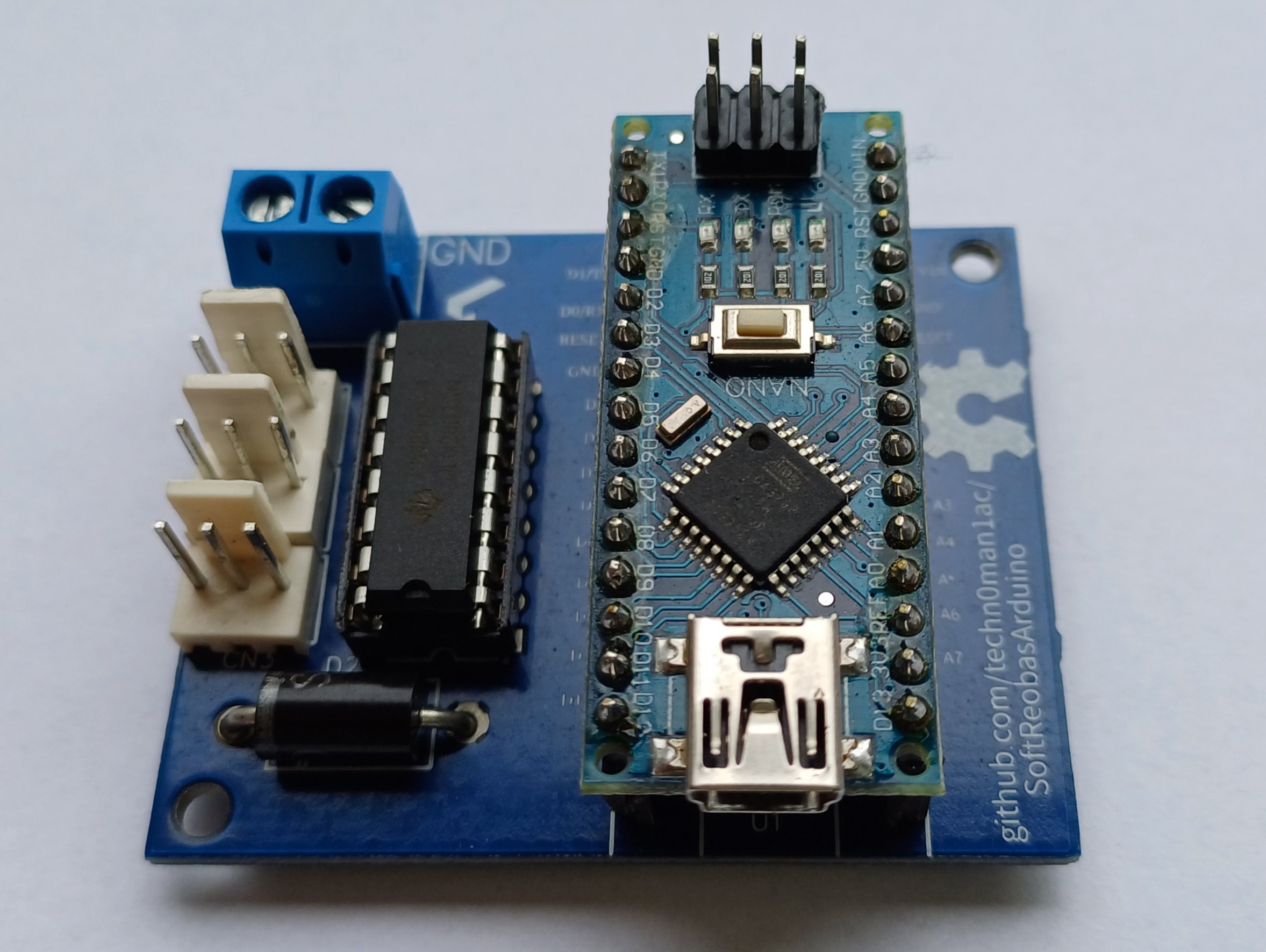
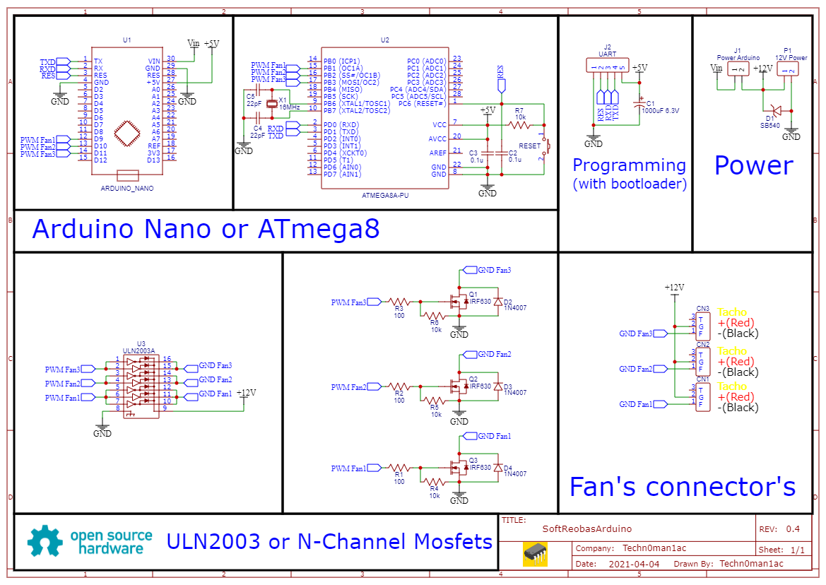
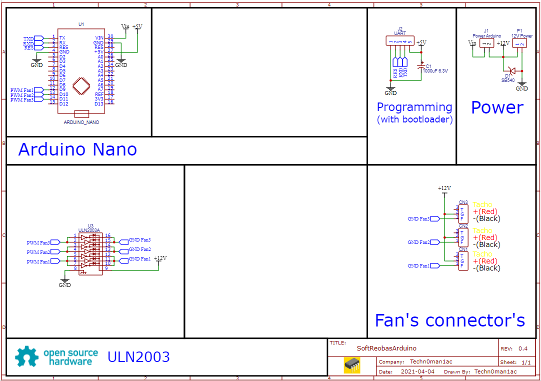
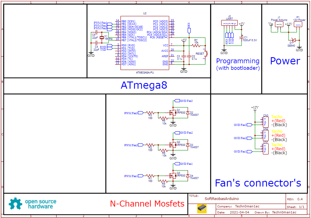
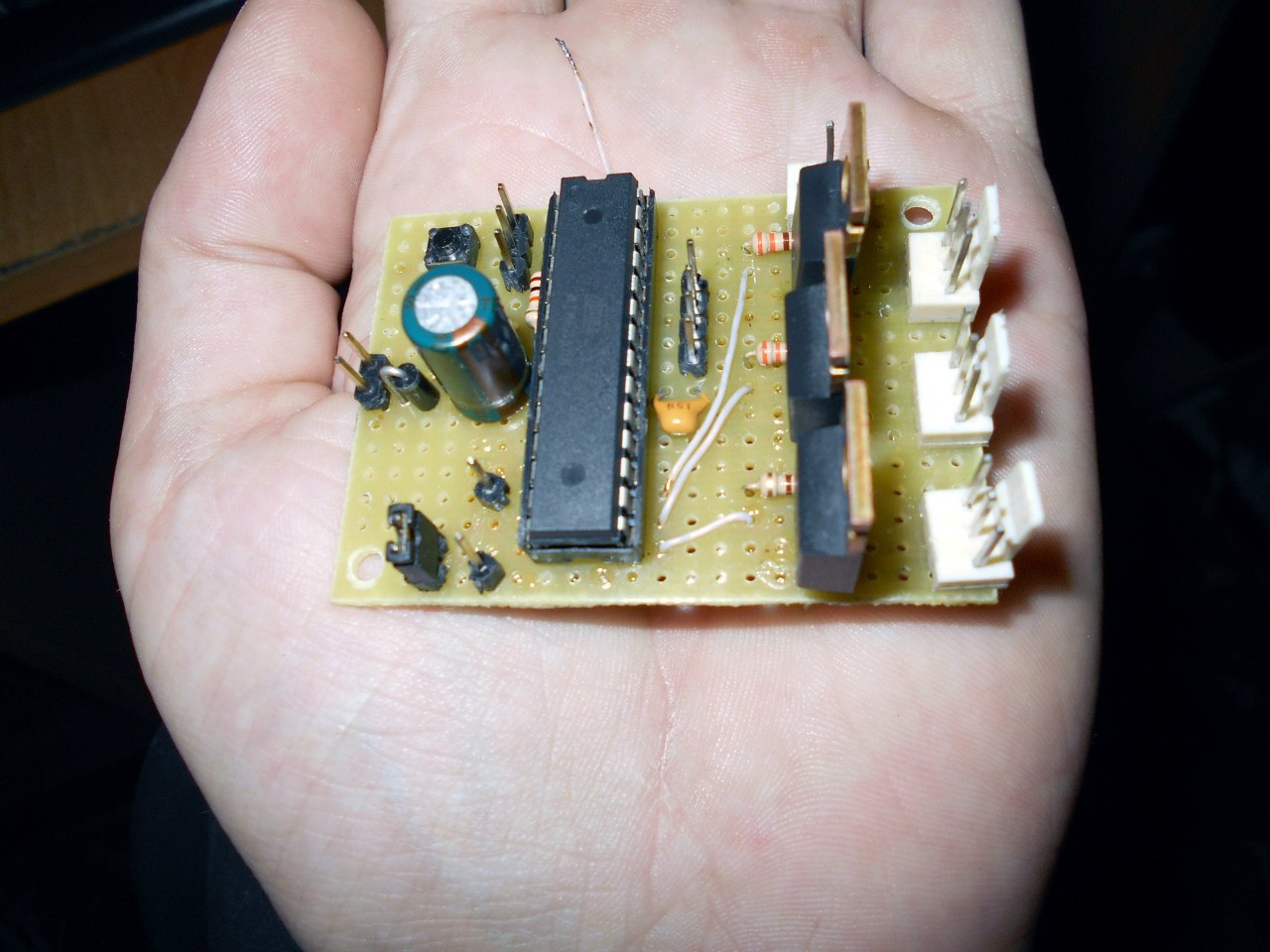
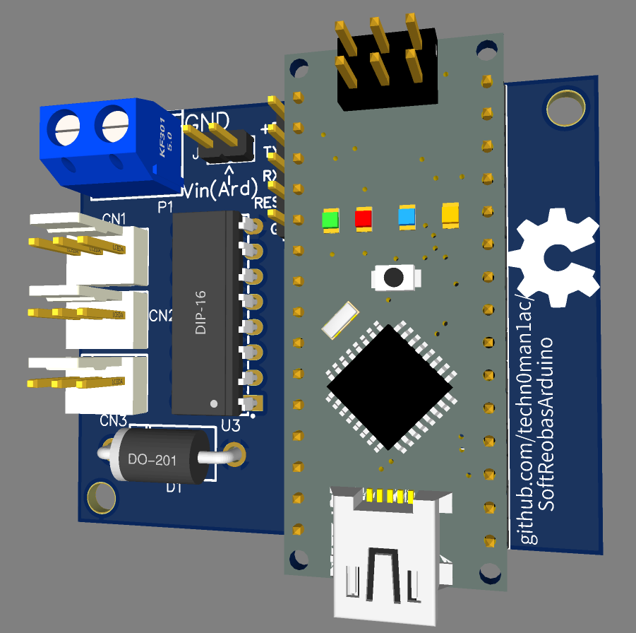
Schematics provide two versions of the board, one - using Arduino Nano and ULN2003(Darlington transistors package), first photo from upper, and second - using ATmega8 CPU and three MOSFET transistors in the TO-220 case(for example IRF540/IRF640/IRF740).
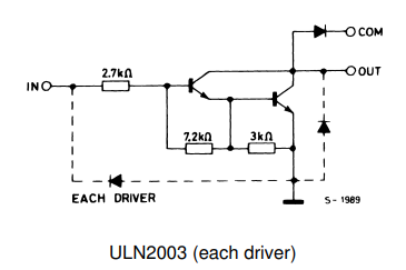
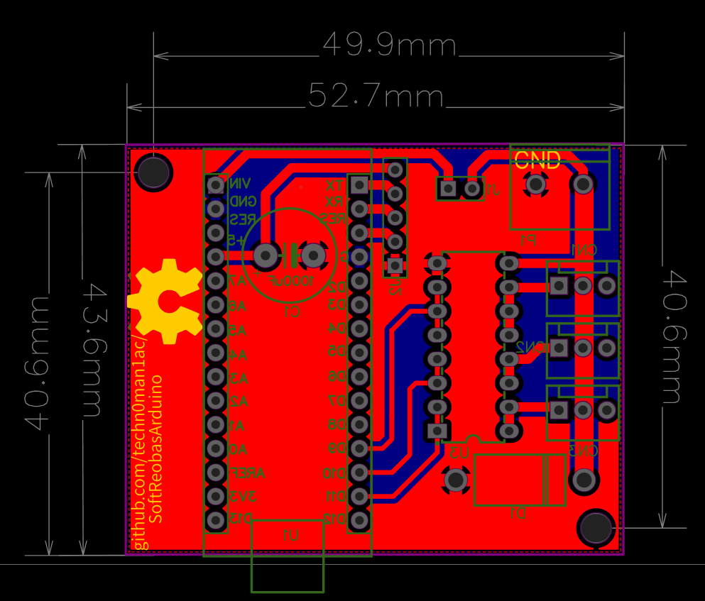
I developed only the first one in PCB format, the second remained in prototype format(last photo). I like the first option because ULN2003 is popular chip that integrates everything from current-limiting resistors to protection diodes in a circuit that only requires a few components:
According to the documentation for ULN2003, the chip can output 500mA per channel, if you look at my schematic, you will see that I have paralleled two outputs for the FAN2 and FAN3 - they can output up to 1000mA per fan, and fan1 has three outputs connected in parallel, correspondingly, the output current can be up to 1500 mA, that is, a more powerful fan can be connected here. However, MOSFET solutions can produce several times more output currents.
You can use both solutions, Arduino Nano or ATmega8, but in the case of ATmega8, you need pre-flash the firmware(with Arduino IDE) and next step - connect a USB-UART adapter to J2 (baud rate 9600), ATmega8 solutuon - need supply +5V for the J2, Arduino Nano have all this in board.
And last - in case ATmega8 you need to know how to Program an AVR Board Using an Arduino Board:
https://www.instructables.com/How-to-program-a-AVR-arduino-with-another-arduin/
The front:
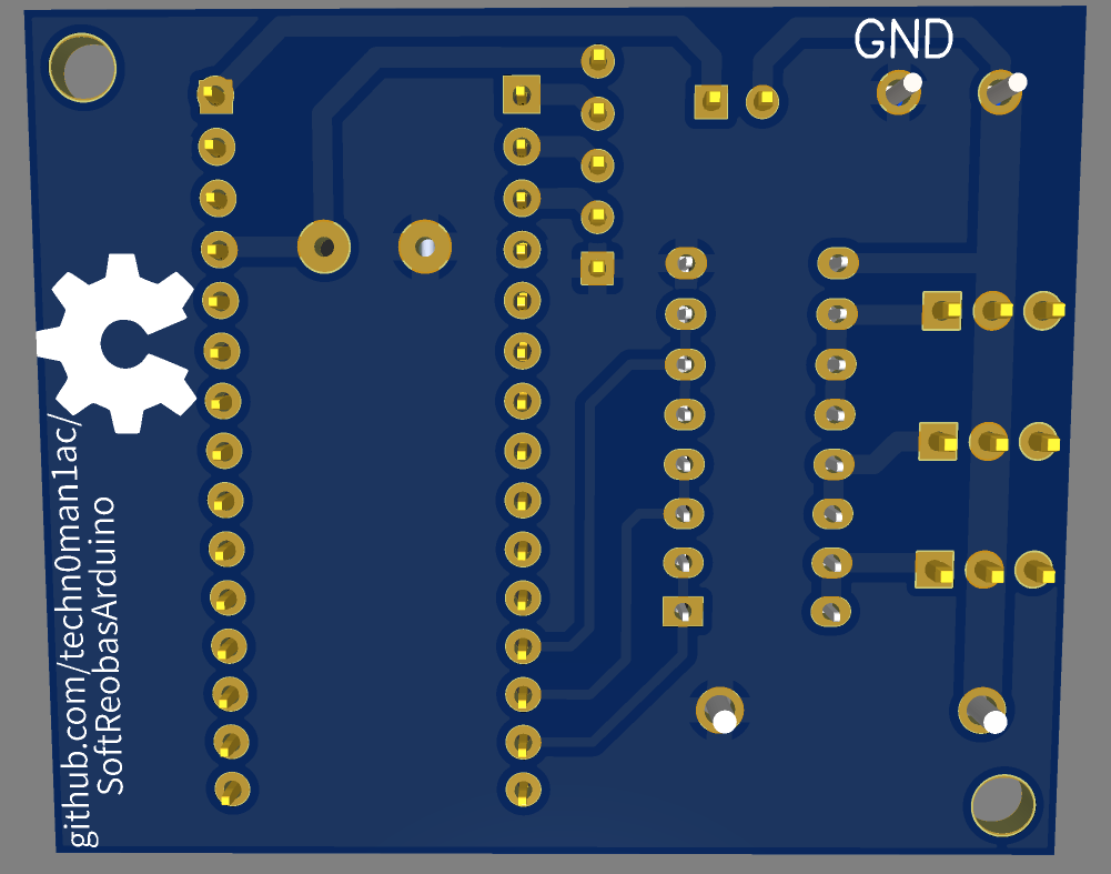
Bottom side:
Board dimensions:
Gerber files for order PCB here:
https://github.com/techn0man1ac/SoftReobasArduino/tree/main/ATmega8Reobas/PCB/Gerbers
Project (circuit and PCB) on EasyEDA(OSHWlab):
https://oshwlab.com/raznie.podelki/softreobasarduino
Source code for Arduino IDE:
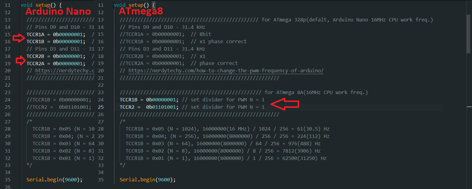
As a CPU, you can use both, ATmega8 or Arduino Nano (by default, the code is selected for Arduino Nano, or ATmega328), if you use ATmega8 CPU, you need to comment out lines 15,16,18,19 and uncomment lines 24 and 25, as in the picture below:
These lines set the PWM frequency at 31 kHz (so that the squeak of the fans is not heard), provided that the controller is clocked at a frequency of 16 MHz. The only thing is that the ATmega8 must operate at a frequency of 16 MHz, that is, it must be clocked from an external quartz.
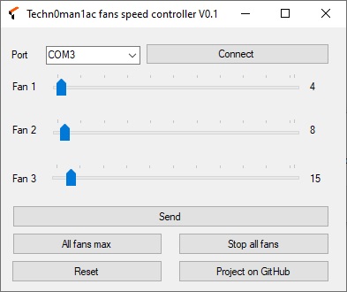
The "Techn0man1ac FSC V0.1" program for PC (tested on Windows 7/10) works as - connect the board to the computer, run program and select "Port" in the drop-down list (top left), choose the number of the USB-UART COM port of the hardware converter, click " Connect" - well done, you can send commands to the board using the user interface buttons:
- "Send" - sends the current values set by the "Fan 1", "Fan 2", "Fan 3" sliders (default is 127, displayed to the right of the slider) to the microcontroller, which stores these values in its EEPROM (non-volatile memory), that is, even after restart the controller will remember this values;
- "All fans max" - this button gives the maximum speed for all fans (also written to EEPROM);
- "Stop all fans" - full stop(without write into EEPROM);
- "Reset" - restart the board;
- "Project on GitHub" - a button that brings the user here to the project page.
Download program "Techn0man1ac FSC V0.1":
https://github.com/techn0man1ac/ATmega8Reobas/tree/main/ATmega8Reobas/WinApp
The protocol of interaction is very simple - the program sends into COM every second the position of each slider in the format d127.64.255 and 127 is the speed of FAN1(CN1), 64 - FAN2(CN2), 255 - FAN3(CN3) but speed is 0..255 like 0..100%, where 255 is 100%.
- If program send "m" - presed button "All fans max";
- "s" - presed button "Stop all fans";
- "r" - presed button "Reset".
CPU recognized its and do some magic - easy peasy, lemon squeeze ;)
Program write on С# in "Microsoft Visual Studio Community 2019 V16.9.2", PS program source code - Fans speed controller(Windows):
Project have Proteus 8 files and full simulate:
https://github.com/techn0man1ac/SoftReobasArduino/tree/main/ATmega8Reobas/Proteus%208
