Updated wiring instructions for Magic LED Controler ?? #231
Comments
|
Original comment by gimi87 (Bitbucket: gimi87, GitHub: gimi87): I started this controller to work (2.0 PCB) and 1.4 version of PCB. Currently i am trying (since i'm discovering git repository) to create a pull request with the code changes and push the graphics with the description. If i will don't do this then i will send an email to the developer about the changes. |
|
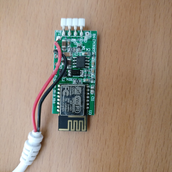
Original comment by Soif (Bitbucket: soif, GitHub: soif): I've successfully flashed this v2.0 board ! While mine has an IR input, wiring must be the same because I've directly soldered to the ESP module (as you can see on the photo). Notice that with this board I had to change the GPI order in hardware.h : happy hacking |

|
Original comment by gimi87 (Bitbucket: gimi87, GitHub: gimi87): I'm so sorry for waiting. I was too busy. Yes this is the correct wiring to program the controller.
So my solution is to use a RST and GPIO0 pin attached to the "dedicated" programmer (like a Witty board or NodeMcu board) which can control additional pins. I attached my code and some graphics with the pin description (and for 1.4 of PCB). -> config/hardware.h -> hardware.ino -> platformio.ini
|


|
Thank you very much, very detailed explanation. |
|
Released with 1.9.6 |
|
Removing milestone: 1.9.6 (automated comment) |
Originally reported by: Vincèn PUJOL (Bitbucket: vincegre, GitHub: vincegre)
Hi
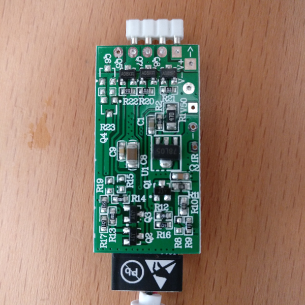
I was looking at Wiki to know how to wire my FTDI adapter on it but discovered mine doesn't have same board as the one in Wiki here: https://bitbucket.org/xoseperez/espurna/wiki/Hardware#markdown-header-magic-home-led-controller
Here are few pictures of it if it can help ??
Thanks!
case.png
The text was updated successfully, but these errors were encountered: