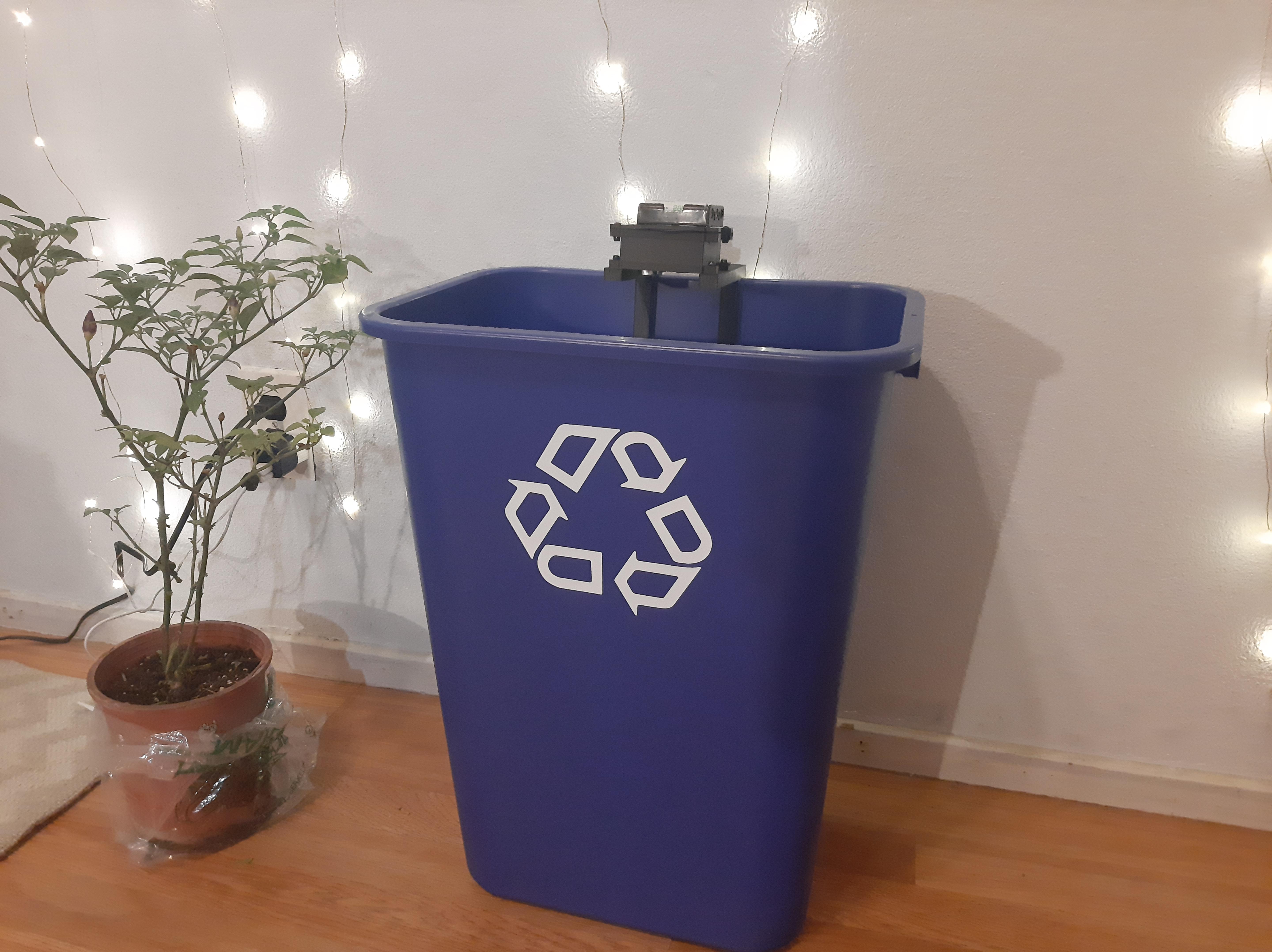
Waste Watcher v1 is an IoT-based sensor module unit that collects bin fullness data and takes images of the trash. The main difference between v0 and v1 is the use of an HTTP server to record data instead of a SD card. This build guide will walk you through the steps of setting everything up. If you need additional help feel free to ask for help on our Discord Server.
- Sends to an HTTP server (You should set up the ZBCE API)
- Modular case design
- Metrics
- bin fullness
- waste images
- Battery Power Integration
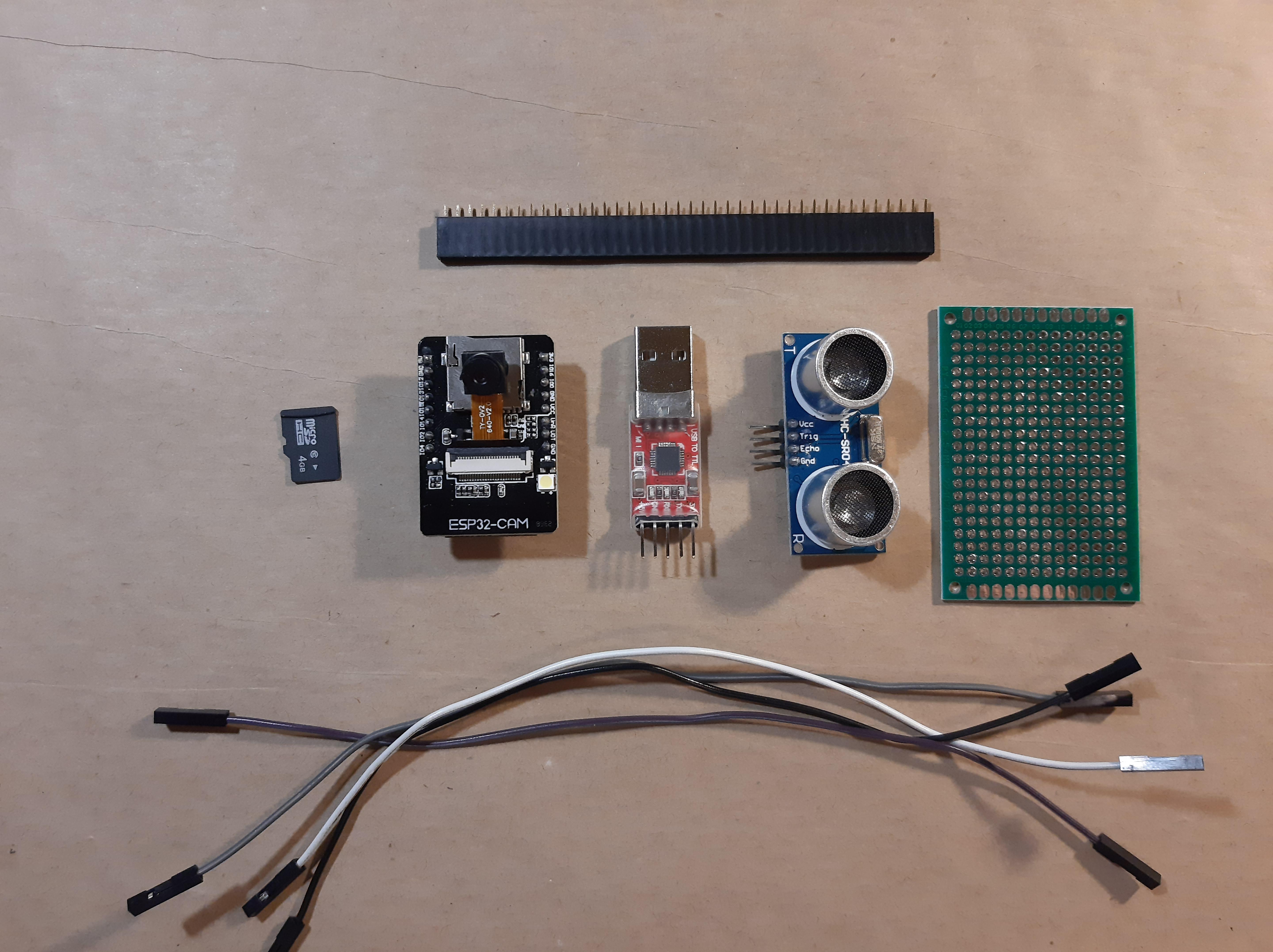
- Supplies
- Solder Components on Prototyping Board
- Download the Arduino IDE and Add ESP32 Package
- Select AI Thinker ESP32-CAM as Board in the Arduino IDE
- Install the NTP Client Library
- Preparing to Upload Code to the ESP32-CAM
- Modify and Upload Code to the ESP32-CAM
- Understanding the Code
- Format and Install Your MicroSD Card
- 3D Printing the Case
- Start Data Logging
-
ESP32-CAM (~$9 per unit)
-
5V Boost Converter (~$1.5 per unit)
-
HC-SR04 (~$1.60 per unit)
-
Solid Wire
-
Prototyping Board (~$0.80 per unit)
-
Female Header Pins
-
Solder
-
PLA Filament
-
8 x 12mm M3 Screws*
-
8 x M3 nuts (nylon nuts recommended)
-
Power Options
- Battery
- 3 AA Rechargeable Batteries (~$4.50 per set of 3)
- 3 AA Battery Case (~$0.76 per unit)
- Direct Supply
- USB cable (stripped to expose V+ wire and GND wire)
- Battery
* 8 mm screws are sufficient, but if you want two bolt the end of the screw you need at least a 12 mm screw (see 3D Printing the Case for a better idea of where the screws will go \
- Soldering Iron
- 3D Printer
- Wire Strippers
- Computer with Arduino IDE Installed
- FT232RL FTDI USB to TTL Serial Adapter Module (~$3.50 per unit)
- 4 Female to Female Jumper Wires
- 1 Jumper Cap or 1 Female to Female Jumper Wire
-
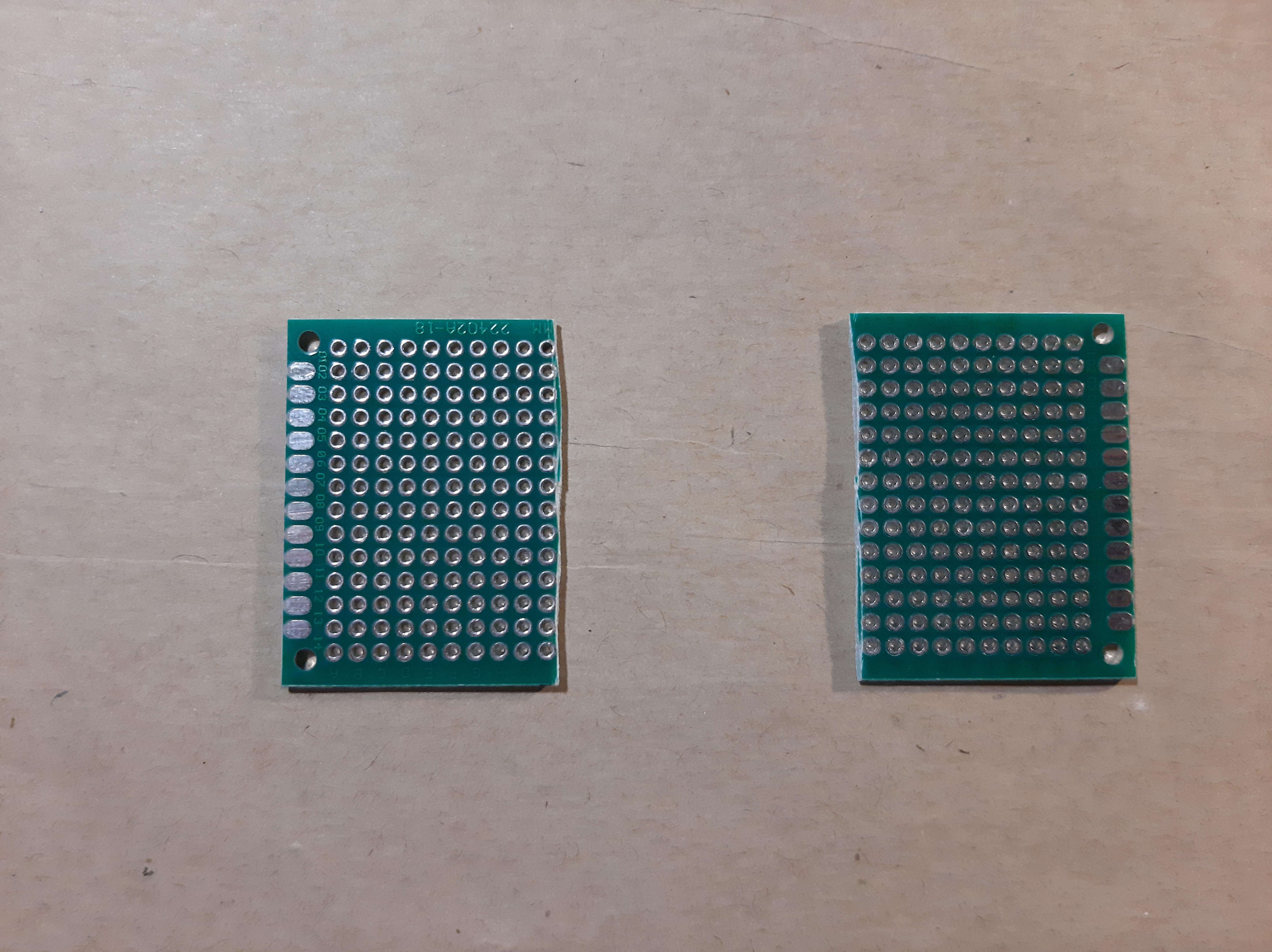
Use a 4cm x 3cm prototyping board. This will be approximately the same size as the ESP32 CAM. I cut a 4cm x 6cm board in half to get that size.
-
Use two 8-pin female headers and place it on the center of board for the ESP32-CAM. I just cut a 20 pin female header piece to get the 8-pin female headers.
-
(Optional) Place a 2-pin screw terminal block connector near the top. You can use this to conveniently plug in my battery pack of 3 AA batteries. If you don't follow this step just solder the wires from your battery pack directly into the prototyping board.
-
Solder wires for HC-SR04 and the 5V Boost Converter. These wires will be used to connect the components to the prototyping board.
-
Solder Components. Once everything is placed, just solder those components in place. See image above of my setup for reference.
-
Plug in your ESP32 CAM into the female headers for referencing the pins. Helps you see which pins for the female headers correspond to which pin on the ESP32 CAM.

-
Solder connections according to wiring diagram below.
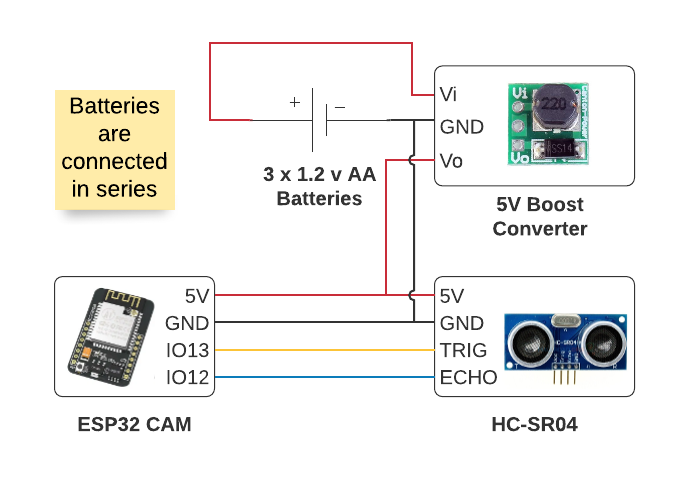
Circuit Explanation
I decided to use the female headers because I wanted to reuse my ESP32-CAM for other projects as well. If you don't mind, you can directly solder everything on the ESP32-CAM.
I was going to write my own instructions for this, but mine was really just going to be a derivative of the one on Random Nerd Tutorials. Their content is really amazing and informative so big thank you and acknowledgement to the blog creators Sara and Rui for making these resources available to the public. So instead, please follow the instructions by watching their video or by following their tutorial, but please stop once you have the Arduino IDE and the ESP32 by Espressif Systems package installed. I will give specific instructions for setting up the ESP32-CAM that varies from the tutorials in the next step.
Video Tutorial: Install the ESP32 Board in Arduino IDE in less than 1 minute (Windows, Mac OS X, and Linux)
Written Tutorial: Installing the ESP32 Board in Arduino IDE (Mac OS X and Linux instructions)
By the end of this tutorial you should have the following:
- An Arduino IDE
- The correct esp32 library added in the Preferences from this source: https://dl.espressif.com/dl/package_esp32_index.json
- esp32 library by Espressif Systems installed from Tools > Board > Boards Manager

Refer to the picture above for reference.
- Near the top left of the Arduino IDE, select Tools
- Then go to Board > ESP32 Arduino > AI Thinker ESP32-CAM
- You might have to scroll down a bit to select AI Thinker ESP32-CAM
We'll be using Wifi and connecting to a NTP server to keep automatically determine the date-time stamp of when the fullness data was collected and when the image was taken. The NTP server is in UTC time, you can add offsets in the code to match your timezone, I explain this in the Code Explanation section.
-
Download the NTP Client Library from GitHub here: https://github.com/taranais/NTPClient/archive/master.zip
-
Unzip the file and go into the folder. Rename the folder NTPClient-master to NTPClient
-
Move the folder to your Arduino IDE installation libraries folder. On Windows, I move the folder here:
C:\Users\REPLACE_WITH_YOUR_USERNAME\Documents\Arduino\libraries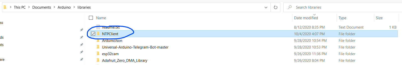 NTP_client_reference.png
 -
Restart the Arduino IDE
Now that you have all the software setup. Let's start with programming the ESP32-CAM.
-
Get your FT232RL FTDI USB to TTL Serial Adapter Module (FTDI Adapter) and your Female to Female Jumper Wires
-
Connect the FTDI Adapter pins to your ESP32-CAM according to the diagram below
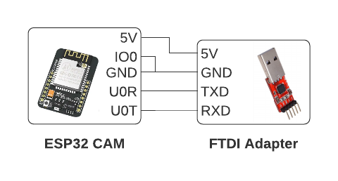
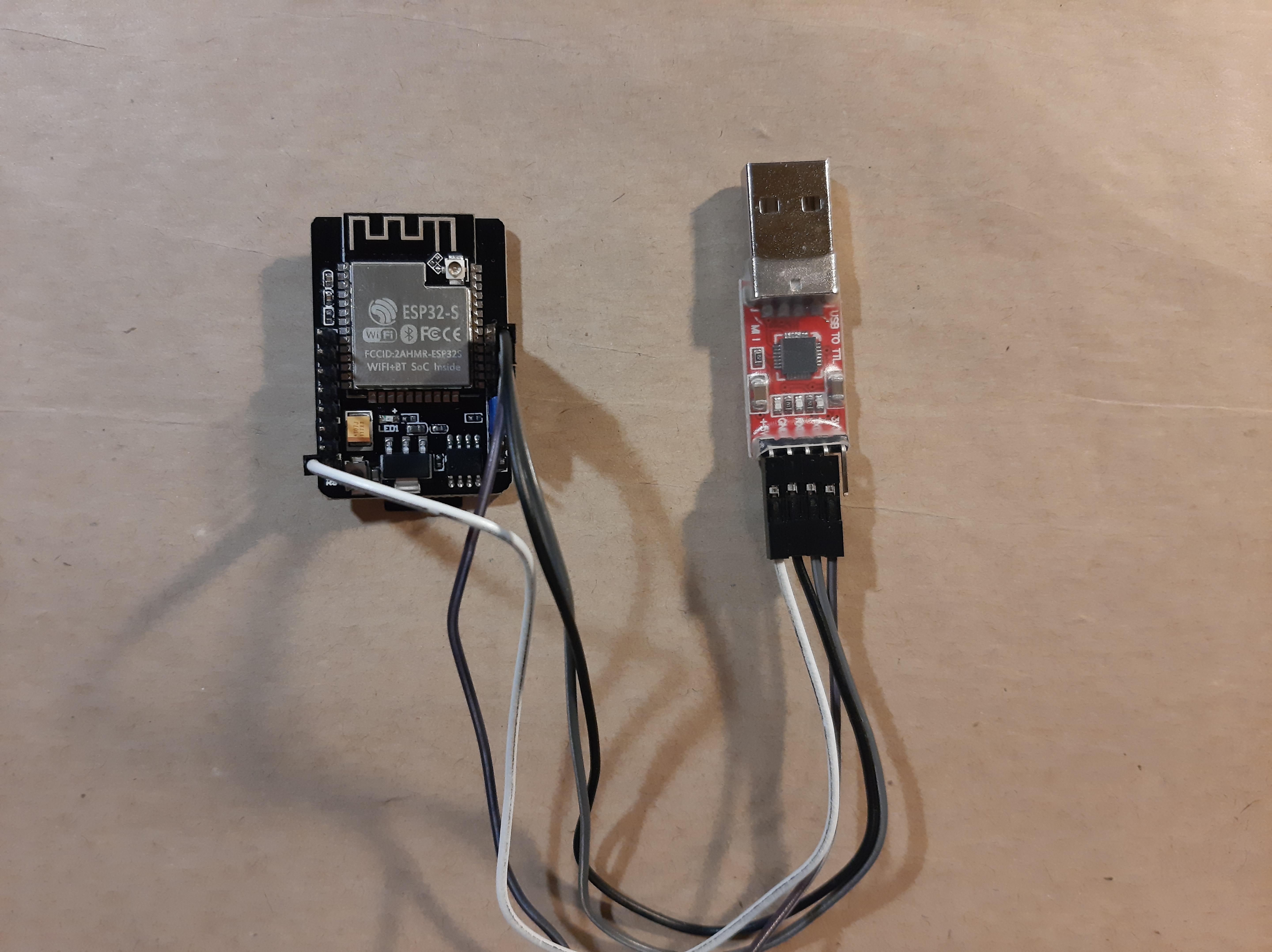
-
Plug in your FTDI Adapter USB side to the computer and make sure that your computer is able to recognize the device. If your computer does not recognize the device follow these steps:
- Locate the required drivers here: https://ftdichip.com/drivers/d2xx-drivers/
- Scroll down to the table and locate the driver for your operating system and follow the instructions
- If you have a Windows machine scroll down to the table and locate the first row and click on the hyperlink labeled as Available as a setup executable
- Once downloaded, run the executable as Administrator
-
Now, we are going put the ESP-32 CAM in programming mode
-
Make sure to connect the IO0 pin to the GND pin using either a female to female jumper wire or a jumper cap.
-
Press the reset push button on the back of the ESP32-CAM and now you should be in programming mode. This will allow you to upload your Arduino Code
Now, we're going to download the code and make some changes so that everything will work. Make sure you are still in programming mode (explained in previous step) and that your FTDI Adapter device is connected.
-
Download the waste_watcher_code folder from GitHub: https://github.com/zotbins/waste_watcher_code
-
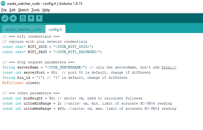
Open up the code in the Arduino IDE. You should see two tabs (one called
waste_watcher_codeand the other calledconfig.h). See image below for reference.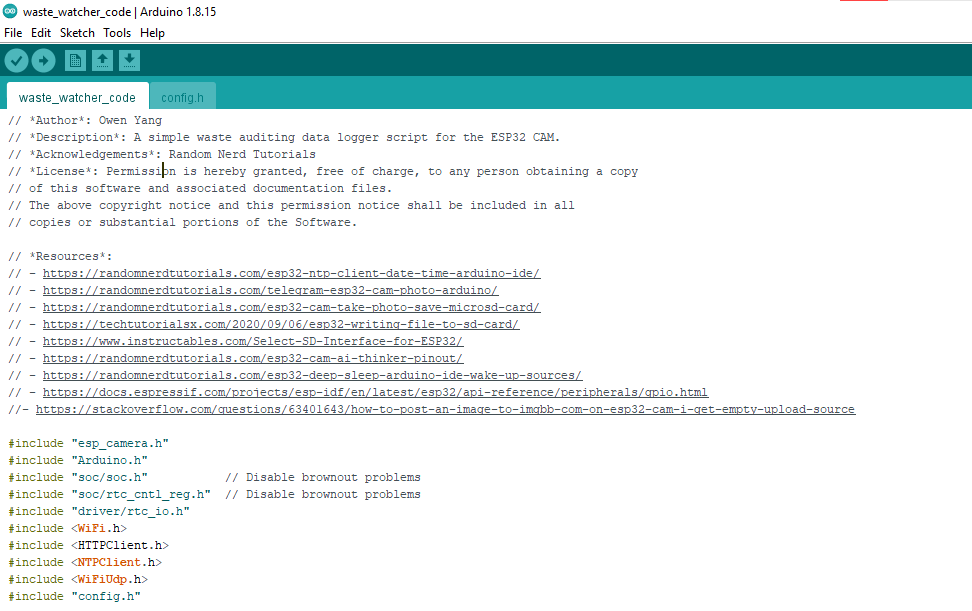
-
Go to the
config.htab so that we can change the parameters -
Change the following variables to match your WiFi Network and your HTTP server that is hosting the ZBCE API
// === wifi credentials ===
// replace with your network credentials
const char* WIFI_SSID = "<YOUR_WIFI_SSID>";
const char* WIFI_PASS = "<YOUR_WIFI_PASSWORD>";

// === http request parameters ===
String serverName = "<YOUR_SERVERNAME>"; // only the serverName, don't add http://
-
Measure the height of your bin and change binHeight value to reflect the height of your particular bin. That way the sensor module can calculate how full your bin is.
const int binHeight = 100; // units: cm, used to calculate fullness
-
In the Arduino IDE, make sure you select the port your FTDI Adapter device is on. Tools > Port
-
Now, compile and upload!
-
To test if the code works, you can open the Serial Monitor on the Arduino IDE, unplug the connection from the IO0 pin and the GND pin, and reset the ESP32-CAM. This should get the ESP32-CAM out of the programming mode and will run the code we compiled and uploaded.
Feel free to skip this section if you are not interested or just save it for later.
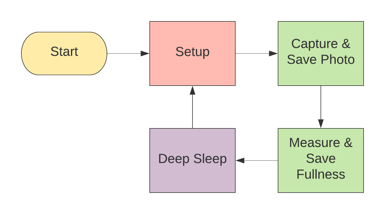
Above, is a quick high-level flow chart that shows the logic of the code. It is pretty simple.
However, if you want a more in-depth explanation, I made a PDF document and made it accessible on GitHub. The code explanation document will go through each block of code and also have some high-level explanation. Please see the code explanation at https://github.com/zotbins/waste_watcher/blob/main/v0/code_explanation.md
- Insert micro SD card into your computer
- Format the SD card to a FAT32 file system
- Once formatted, insert it into your ESP32-CAM
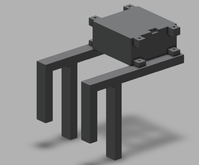
- Download the the STL files from https://github.com/zotbins/waste_watcher/tree/main/v0/stl_files
- Infill: 10-15%
- Supports: Everywhere
- Print two of the sensor_mod_handle.stl
- Print one of the sensor_mod_top_assembly.stl
- Print one of the sensor_mod_bottom_assembly.stl
Currently, this design only fits on a bin with a 1cm width lip. You may have to modify the CAD file. I have included a Fusion360 file called sensor_mod_handle v9.f3d, in the github repository, that you can modify to fit your needs. Another option is to design your own handles for your bin, I made the case pretty modular where you can create a custom attachment with M3 screws.
By this step, you should have uploaded the code to the ESP32-CAM with the micro SD card inserted, have a prototyping board with the soldered circuit (HC-SR04, Female Headers, Battery Pack Holder) on it, and have a enclosure for all the components.
- Plug in ESP32-CAM into your prototyping board
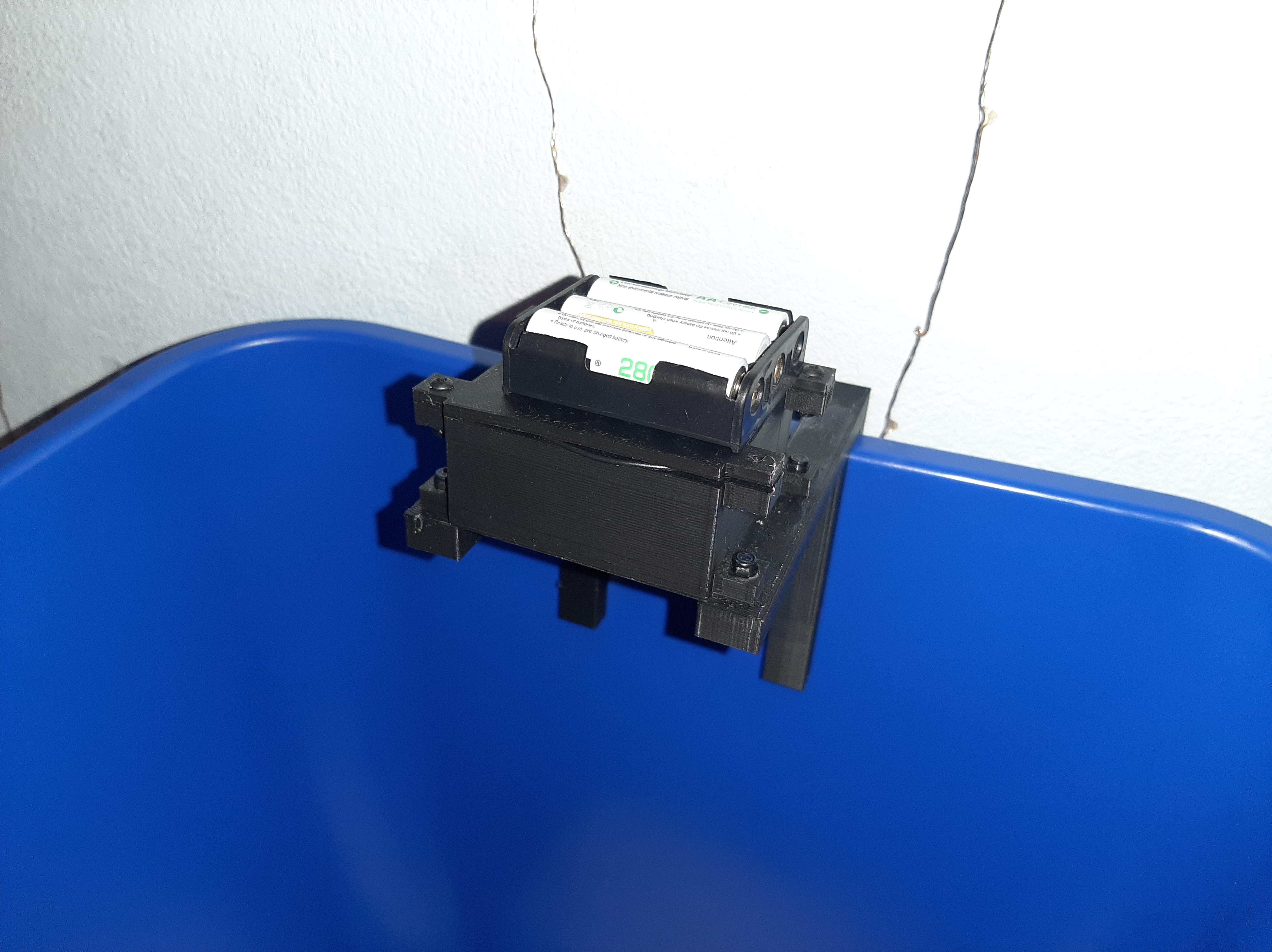
- Put the assembled board into your 3D printed enclosure
- Attach the enclosure onto a waste bin
- Power your module w/ either the a 5V battery pack or a 5V USB cable
- Congratulations! The code should start running and logging data!
- After a period of time, you can go ahead and check the server and look at what you've thrown a way and also see the fullness trend over time. It's definitely more meaningful to collect data over a long period of time than a short period.
Debugging
- The flash on the camera should flash really brightly once and then go into deep sleep.
- If it keeps on flashing a couple times repeatedly every few seconds or so that means that the ESP32-CAM failed to connect to the camera module. Try resetting the board
- More debugging tips to come as I use this more and as I receive more feedback