News Update. THIS PROJECT IS FAILED DUE TO LOW RESPONSIBLE TIME AND ON BOARD MCU SHIFT THINGS OUT TOO SLOW.
Talk directly to the display via STM32 (using HAL).
Display static grayscale image on GU7000-series VFD display from Noritake Itron.
NOTE:It's just the concpet that has not been tested yet. But in theory should work.
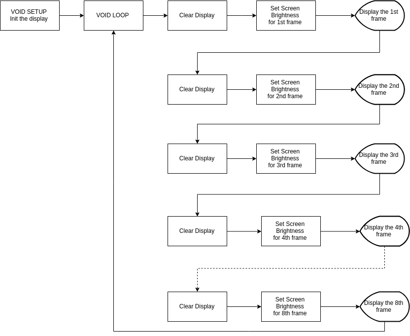
This project can turn your GU7000 series VF display (manufactured by Noritake Itron) into the grayscale-able display. In this case I use GU280x16G-7000. I use ESP-01S and communicate with the display through Async(rs232) but it's 5 volt bus. GU7000 VFD display capable of 8 brightness levels and we can change brightness anytime without to re-init the display. The GU7000 series have feature to display static monochrome image. but what happen if we can display multiple bitmaps and every bitmap has it own brightness level. we can combile multiple bitmaps with multiple brightness levels then our eyes will pick up as static image. This phenomenon call "POV" stand for Persistence Of Vision. It's like tricking our eyes. the flow-chart in the image below is the workflow of FakeGrayscale in void loop. Start from the initializing progress in void setup then jump to void loop. This begins the process of FakeGrayscale.
Software : Arduino IDE and Noritake Itron GU7000 modified library in this repo.
Hardware : In this case I use GU280x16G-7000 Display. You can use any GU7000 series. About Microcontroller. I use ESP-01S.
I modified the Library to at lease fix compile error. but not testing the library yet.
You can change the communication types, baud rate, pinout for arduino and other configuration that need to be done on the real hardware and code itself. for example. My VFD display (GU280x16G-7000) accept Parallel 8bit and Async (RS232) communication method. I prefer the Async because it fit with the ESP-01S use (TX RX and GPIO). Baud rate I will config at 115200 (Maximum) because it's fastest method for my ESP-01S.
Go get arduino IDE first. then setup the ESP8266. You can watch tut on youtube. After done these then go to these steps down below.
sudo apt-get install git
git clone https://github.com/TiNredmc/FakeGrayscale.git
cd FakeGrayscale
mv Library/ GU7000Mod/
cp GU7000Mod/ /your/dir/to/Arduino/libraries
NOTE: you can use your file manager to rename the Library folder. If you have your original library of Noritake. you need to move to other place. overwish IDE will decides to select multiple same library. cp command isn't actually required if you prefer file manager. you need to copy the library to the libraries folder in your Arduino folder. You can find tutorial how to install library manually on youtube.
After done steps above. Execute the Arduino IDE and open the sketch in the FakeGrayscale folder. or open the sketch from the folder via file manager.
to check if everything is right. it will looks like this

next thing to do is select the board setting. you need to use the CheckFlashConfig code to determine the correct flash size and flash mode. Like ESP-01S, The flash size I selected 1M (no SPIFFS) because I don't use OTA update.
after everything set up. you need to know how to flash ESP-01 using USB to UART TTL or what ever. after uploaded, connect the Display to ESP-01S by
Display=============ESP-01S
GND                 GND
SIN                 TX
RESET               RX
BUSY                GPIO2
NOTE: The display shared same ground with ESP-01S but the display need 5 volt and ESP-01S need 3.3 volt. So you need voltage regulator from 5 volt to 3.3 volt for ESP-01S. Like mine I use The USB to UART. It has 2 voltage rail. one for 5 volt and one for 3.3 volt. I can use this to power up whole project using just USB. According to Display module datasheet. It takes about 200mA. The USB to UART can deliver up to 500mA so that's not the problem.
vfd.begin(Display width ,Display height); // width and height of Display. Mine is 280x16.
vfd.interface(interface); // select interface type to communicate with the display.
vfd.isModelClass(7XXX); // type in your model calss of your display. Mine is 7000.
vfd.isGeneration('B'); // uncomment in the code if you use the 7XXXB version.
vfd.GU7000_reset(); // reset the display module. to clear any ghosting on RAM.
vfd.GU7000_init(); // Initialize the display.
vfd.GU7000_clearScreen(); // clear the RAM of the display to make it COMPLETELY blank.
vfd.command(0x0c);
vfd.GU7000_setScreenBrightness(1-8); // set the brightness from 1 to 8. use this command to create FakeGrayscale brightness.
vfd.command(0x1f, 0x58, 1-8);
vfd.GU7000_drawImage_p(bitmap width ,bitmap height ,bitmap's array name); // display the bitmap from PROGMEM.
Noritake Itron For the library and the bitmap hex generator tool.
noisetexturegenerator.com For the noise images
meking66 (UK eBay seller) For selling me the display.
techcrunch-fr (Chinese eBay seller) For the ESP-01S and the adapter mode.
GU280x16G-7000 : https://www.ebay.com/itm/NORITAKE-ITRON-GU280X16G-7000-VFD-MODULE-BRAND-NEW/232628526042?ssPageName=STRK%3AMEBIDX%3AIT&_trksid=p2057872.m2749.l2649
ESP-01S and adapter : https://www.ebay.com/itm/1PCS-ESP8266-ESP-01S-Serial-WIFI-Wireless-Transceiver-Module-Adapter-PCB-Board/173587512779?ssPageName=STRK%3AMEBIDX%3AIT&var=472268429424&_trksid=p2057872.m2749.l2649