Discover Sigfox and Sens'it by building a real-life cold storage management solution
The goal of this repo is to learn how to build a real-life application using Sigfox and Sens'it.
Learn everything you need to know about Sigfox's technology, its advantages and its limitations. Then use that to build whatever you can imagine with the open hardware, firmware and software that is out there.
You can learn it in just a couple of days!
-
Sigfox
a. The technology
b. Sigfox Backend, Sigfox Cloud Platform, REST API and Callbacks
c. Visualizing your data and Sending instructions: Callbacks and Downlinks
d. AT commands -
Sens'it
a. The device
b. SDK and setup
c. Troubleshoot -
Build your own application with Sens'it
a. Presentation
b. Main
c. discovery.c
d. discovery.h
e. Makefile
f. Creating a dashboard in Losant
Sigfox is a Low Power Wide Area Network (LPWAN) complementing existing networks to address the bulk of connected objects.
Sigfox invented a Radio Protocol and used it to build a global network adapted to small data transactions (like the ones generated by objects). Sigfox does not build IoT solutions or sell chipsets. Other IoT networks, like LoRa, exist.

Sigfox's network enables your everyday object to send data captured by its sensors.
The data can then be processed and give new insights on optimizable processes.
However, it is important to understand that the payload (data) that can be sent over Sigfox's network is limited in:
- size (maximum 12 bytes) - this is intrinsic to how the LPWAN technology works, we will come back to that;
- frequency (140 messages a day max) - that is due to the fact that Sigfox uses a public radio frequency and cannot hog it

One BIG advantage of Sigfox's network is how the LPWAN communication works: devices are not connected or paired to antennas, nor do they need to signal their existence regularly (unlike cellular networks). LPWAN works on the Aloha mechanism: "if you have data to send, just send it!"
Antennas are constantly in "Listening mode" and devices can send data whenever they need to (the data is encrypted with an authentification key).
- If antennas are in the area, they will capture it and send it to Sigfox's cloud (through an internet connection)
- If there are no antennas in the area, the message will be lost - in order to increase the chance of an antenna receiving the message, every device will send the same message three times at different moments and frequencies, enabling time and frequency diversity

Therefore, being sure that coverage is available in your area is very important. But worry not, Sigfox network is in constant deployment and offers a wide coverage already, nation-wide in some countries. Check their coverage map here.
Sigfox takes care of the deployment of their own antennas. Which means that you won't need to invest in antennas, their installation nor their maintenance etc., zero CAPEX for you.
The only expense on your side is the connectivity fee that local operators will charge you. Check the pricing for your country here.
So, what is that BIG advantage we were talking about?
There are actually three!
First, this means that your device is constantly in "Sleep mode", and only turns on when it needs to send a message (max 140 times a day, so once every 10 minutes and 16 seconds more or less). This explains why it consumes so little energy (less batteries to change -> IoT solutions are more ecological and economical).
But, most importantly: your signal can travel over very long distances and it cannot be jammed! Unless you have an army-graded jammer...

To jam a signal you have to jam the receiver. As there is no pairing between the device and the antennas, the only receivers in the Sigfox network are the antennas. So, to jam a Sigfox-ready device's message you'd have to jam all the surrounding antennas (one is not enough, since all surrounding antennas will be listenning - spatial diversity).
You could also imagine drowning the device's message in noise, but that too is impossible! As shown in the graph above, the LPWAN uses Ultra Narrow Band (UNB) signals. Sigfox's bandwidth is very narrow (therefore messages sent through it have to be small - 12 bytes max) but this means that every signal will have a very high density - a lot of energy concentrated in an ultra narrow band. A jammer cannot produce enough energy to drown those signals in noise.
Plus, an UNB signal will be powerful enough at its source to travel over very long distances. That is why it's easy imagining IoT applications in the industrial, agricultural, retailing and transportation areas.

Sigfox also allows you to send messages to your device (imagine wanting to change a parameter on your device: the sensitivity of a sensor, closing a valve or making a LED blink to signal acknowledgment of the message by the network...).
That is what we call a downlink (in opposition to the uplink messages that we have been describing until now).
Downlink messages cannot exceed 8 bytes, and Sigfox only allows 4 downlink messages per device a day...
Here you can see what UNB means and how Sigfox uses its bandwidth to send messages in both directions:

(RCx are the different radio regions in the world - the public radio frequency used by Sigfox in each region of the world. Your device has to be compatible with your region's radio frequency - the antennas around you will be listenning on that frequency)
When your device wants to receive a downlink message, the device is actually the one that instigates the communication. It will start by sending an uplink message to Sigfox's network (12 bytes max) with a special command (see more here). Instead of going back to "sleep mode" immediately it will go into "listenning mode". The network will then send a downlink message (8 bytes max) on a randomly selected frequency of downlink agreed with the device. The device receives the downlink message, processes it however it is programmed to and will then go back to "sleep mode".
To sum up:
- Sigfox invented a Radio protocol and is deploying a secured network that enables your objects to communicate (no CAPEX for you)
- The network is limited in frequency (max 140 messages per device a day) and in bandwidth (messages's size cannot exceed 12 bytes)
- This is due to how the LPWAN technology works, which also gives a lot of advantages: low energy consumption, long-distance communication and anti-jamming technology
- You can send messages in both directions between Sigfox and your device (max 4 downlink messages per device a day that cannot exceed 8 bytes in size)
A Sigfox-ready device incorporates a Sigfox radio module. The module allows it to send and receive messages from the Sigfox antennas. But, in order for that to work, the device has to be activated.
If you buy a ready-to-use device, it will most certainly already be activated.
If you're using a devkit (as the ones here) then you will need to activate it. Follow the very simple steps listed here: https://support.sigfox.com/docs/sigfox-activate:-when-and-how-to-use-it
Your device will have an ID that it uses to identify itself on the network (check for a label on the back of your device with a mention of an ID).
It also uses a second number called Porting Authorization Code (PAC) that you can probably find following these instructions.
These identifiers will come in handy if you want to register your device on Sigfox's backend.
This document explains what Sigfox's backend is and how to use it.
TLDR: It basically allows you to manage all your connected devices, connect new ones and manage how messages received from/sent to your devices should be handled (more on this here).
Most of your Sigfox-ready devices will come with an app or website that allows you to visualize the data sent by the device. In that case, you don't need Sigfox's backend, since the manufacturer will have taken care of that.

The devices send messages received by antennas > The antennas send the data to Sigfox's cloud (Sigfox's backend allows you to manage what happens from there on) > The data is usually then sent to data visualization apps or trigger an action or a response (downlink)
If your device doesn't come with an app and you need to build one yourself, this is how you do it.
You will have to setup callbacks or use Sigfox's REST API. Learn more on that here.
Once that is set up you will be able to see your messages being sent and decide what Sigfox should do with them (like a manufacturer would do to build their own app).
One of the things you could do with the data sent by your devices is building a dashboard to visualize them. Two platforms can be very useful for that: Losant and Ubidots. There are many other platforms that can do this, feel free to use the one that you prefer.
How to build a dashboard on Losant to visualize data received through Sigfox callbacks
How to do that with Ubidots
These platforms also allow you to send a downlink message as a response to a callback. To setup that kind of downlink messages follow these steps.
In Losant you can describe what the downlink message should be in the "Webhook reply" block.
For Ubidots, everything is explained here.
In this doc you can see the mention of a "Direct" Downlink mode. If you use that, the data you insert in the "Downlink data in hexa" field will be sent to any device of that Device type that asks for a Downlink message at any time (remember you can only send 4 downlink messages a day per device - and they can't exceed 8 bytes in size).
Finally, it is important to know how to ask for a Downlink message.
As you can read here Sigfox module is controlled through what we call AT commands. You don't need to know much about it. Maybe just that this is what you will need to write if you want to give orders to the Sigfox module. For example, to send a message you will have to send this command to your module:
AT$SF=frame[.bit]
where the frame is the data you want to send (max 12 bytes - max 140 messages a day per device) in hexadecimal base.
The way you actually write this in your code depends on the device you're using - in the example below it is done with the function SIGFOX_API_send_frame described in sigfox_api.h header file.
In simpler examples, like the ones you could find for prototypes that use an Arduino board, you might just need to write Serial.println("AT$SF=data") after turning on the module with digitalWrite(sigfoxModulePin, HIGH).
By the way, you can also get the ID and PAC of the device with this command:
AT$I = Unit
Unit ranges any value from 0 to 11.
The units' meaning might change from one device to the other (depends on the module used), check it on your device datasheet (if available...). For example, 1 might give you the ID and 11 the PAC.
What you need to know regarding Downlink messages is that the network will know your device is waiting for a Downlink message if in the message that it sent (AT$SF=frame command) it includes ,1 at the end of it.
Example:
AT$SF=ffee1234,1
In this case the data sent was "ffee1234" (0xFFEE1234 = 0b1111 1111 1110 1110 0001 0010 0011 0100) and the network knows that it has to send a Downlink message back because of the ,1.
What it sends back depends on what you configured in the backend as explained before (here).
There are a lot of options out there to get started with Sigfox and start developing your own device. As long as you have a Sigfox module on your devkit, you're good to go. Connect whatever sensor you need and start coding.

Devkits you could use:
https://partners.sigfox.com/products/kit
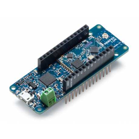
If you've used Arduino or Raspberry Pi before, there are some compatible devkits in the link above. They are pretty easy to handle and usually come with extensive documentation on how to enable the Sigfox module and how to send a message.
Examples using an Arduino compatible board like MKR FOX 1200
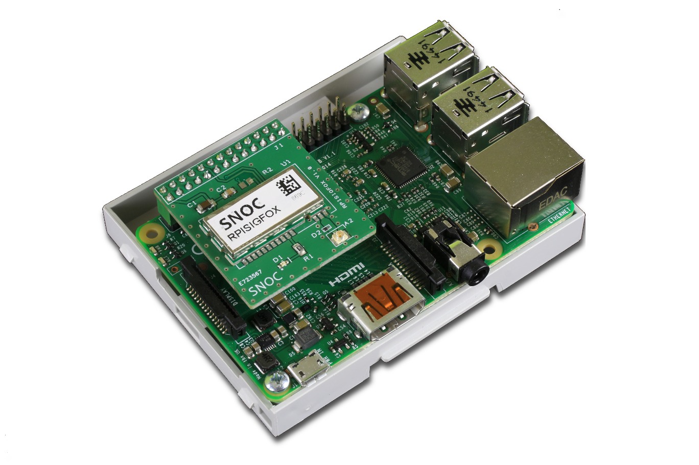
Examples using a Raspberry Pi compatible board like SNOC's expansion board
If you have never worked with these boards before, feel free to choose what suits you best, but know that Arduino and Raspberry Pi are always good starting points for prototyping. They have a large variety of compatible sensors and a lot of available documentation.
In this tutorial we will not be using either of those options (as we will be using the Sens'it), but they were a good way to get started with Sigfox and understand how messages are sent, processed and received.
Once you get going, try connecting your prototypes to Sigfox's backend and check out the output (as explained here).
These links can be very useful:
Learn how to parse and decode the data contained in the payload sent by your device. Use a platform (e.g. Losant or Ubidots like explained here), if you wish, to build your first complete application with decoding, workflows and data visualization.
Sens'it is a multi-sensor device that uses the Sigfox Network to communicate.

It embeds a button, two LEDs, a temperature & relative humidity sensor, an ambient light sensor, an accelerometer, a magnetometer and a reed switch. Download its datasheet here.

Sens'it 3 is perfectly suited for anyone who wants to get started with IoT:
- As an end-to-end solution with Sens'it Discovery.
- As a devkit, thanks to the Sens'it SDK.
- In batches for roll-outs of custom solutions with Sens'it Generic by Altyor.
The Sens'it SDK makes it possible for you to change the behavior of the device to match your needs. Here we take advantage of that to turn the Sens'it into a multi-sensor device for cold storage management.
The first thing you want to do is register your Sens'it as a Devkit. You will find info on how to do that here.
After that you will need to download and setup the SDK.
For Windows: simply follow these instructions
For Mac: the same instructions apply. However, these next few tips will also come in handy:
- Download and install dfu-util using Homebrew
brew install dfu-util
-
Put the GNU Arm Embedded Toolchain folder (
gcc-arm-none-eabi-8-2018-q4-major) inside thesensit-sdk-v2.0.0folder (try following the same structure as the one in this repo - this will affect how you have to modify the Makefile inside the SDK folder). In this repo we renamedsensit-sdk-v2.0.0toSensit_project, this folder is your C project. -
In the Makefile (
sensit-sdk-v2.0.0 > sdk > Makefile) modify these adresses as follows (or according to how you organized your folders):
# ---------
# TOOLCHAIN
# ---------
CC = ../gcc-arm-none-eabi-8-2018-q4-major/bin/arm-none-eabi-gcc
BIN_TOOL  = ../gcc-arm-none-eabi-8-2018-q4-major/bin/arm-none-eabi-objcopy
SIZE_TOOL = ../gcc-arm-none-eabi-8-2018-q4-major/bin/arm-none-eabi-size
- You may also need to add the serial of your device to the dfu-util commands at the bottom of the Makefile (to know what it is, once your Sens'it is connected and in Bootloader mode, write
dfu-util -linto your terminal - the serial you are looking for is the one with this namename="@Internal Flash /0x08000000/032*0001Kg"). You can also add some commands like these ones:
prog:
	dfu-util -a 0 -s 0x08000000:leave -D $(BIN_PATH)/$(BIN_OUTPUT) --serial FFFFFFFEFFFF

reset_prog:
	dfu-util -a 0 -s 0x08000000:leave -D ../bin/sensit_discovery_v3.1.1.bin --serial FFFFFFFEFFFF

upgrade:
	dfu-util -a 0 -s 0x08000000:leave -D ../bin/upgrade.bin --serial FFFFFFFEFFFF

backup:
	dfu-util -a 0 -s 0x08000000:32768 -U ../bin/backup.bin --serial FFFFFFFEFFFF

restore_backup:
	dfu-util -a 0 -s 0x08000000:leave -D ../bin/backup_og.bin --serial FFFFFFFEFFFF
Make yourself familiar with how your folders are structured, so you know where to find header files (project_folder > sdk > inc) and the .c files (project_folder > sdk > src). A lot of errors can come from this and a lot of solutions can be found in these files.
Make sure you generate a backup file and that you don't delete it!
Whenever you restore the backup into the device, remember you will need to re-update it before uploading any other code (if not, it will fail).
Remember that to upload something into your Sens'it it has to be updated, connected and in bootloader mode.
If anything goes wrong, a good way to restart from scratch is to restore the backup, so again: DON'T DELETE THE BACKUP FILE!
If you can't go back to bootloader mode (or if the LED turns red when you try updating the device) you can:
- disconnect the USB
- disconnect the battery
- hold the button
- reconnect the USB Then, without reconnecting the battery, upload a program onto the device (in this case you'll usually want to upload the backup...), then reconnect the battery and resume your activity (or start over).
If your device is stuck in bootloader mode, disconnect the battery, wait a bit and reconnect it.
Once the setup is done and you've gone through the troubleshoot list way more times than you'd like to admit, you're ready to build your own application with confidence.
To check that everything is fine try writing make main or make temperature (or any of the commands in the Makefile that have already been coded by Sens'it's team - look for them in the COMPLETE BUILDING part) and then make prog (with your Sens'it connected and in bootloader mode). If it loads correctly, everything's good!
Ok, now you're ready to write your own code. Soon, you'll be able to write make app and make prog and load your own app into the Sens'it like a pro.
The example in this repo turns your Sens'it into a multi-sensor device for cold storage management (for a supermarket fridge basically...) It will:
- keep track of the temperature and humidity inside the fridge (one message sent every 20 minutes and in any message sent by the device)
- count the number of times the door has been opened (if it is opened way more times than products are sold, it might mean the products inside are too hot or that the fridge is empty...)
- send an alert if the door is left open (more than 1 minute)
- send an alert if the fridge is being moved too violently (in case of robbery for example)
- send an alert if the button is pressed twice quickly (we could imagine this being used as an Amazon Dash button - if you need more Coke in your fridge, press the button and more Coke will be delivered to you)
The first thing you want to do is fork (duplicate and rename) from main.c or any other main_X.c that might seem interesting or close to your idea, to main_APP.c (here, main_FRIDGE.c). main.c contains a blank template and is the template given by Sens'it's team for you to start coding.
In this case, the main_FRIDGE.c file started with the empty template of main.c. Parts from main_MAGNET.c, main_VIBRATION.c and main_TEMPERATURE.c were then inserted (a few lines of main.c were also removed) to use the sensors as needed.
Don't forget to add #include "discovery.h" at the top of the blank template (because it is not included in main.c).
Find the whole code for the main here.
You will then need to modify discovery.c and discovery.h accordingly.
In the discovery.c file you need to modify the DISCOVERY_build_payload function. In this case we added a new mode:
...
else if ( mode == MODE_FRIDGE )
    {
        if ( data->temperature < TEMPERATURE_MIN )
        {
            payload->special_value = (TEMPERATURE_MIN + TEMPERATURE_OFFSET) >> 8;
            payload->temperatureLSB = (u8)(TEMPERATURE_MIN + TEMPERATURE_OFFSET);
        }
        else if ( data->temperature > TEMPERATURE_MAX )
        {
            payload->special_value = (TEMPERATURE_MAX + TEMPERATURE_OFFSET) >> 8;
            payload->temperatureLSB = (u8)(TEMPERATURE_MAX + TEMPERATURE_OFFSET);
        }
        else
        {
            payload->special_value = (data->temperature + TEMPERATURE_OFFSET) >> 8;
            payload->temperatureLSB = (u8)(data->temperature + TEMPERATURE_OFFSET);
        }

        if ( data->humidity > HUMIDITY_MAX )
        {
            payload->humidity = HUMIDITY_MAX;
        }
        else
        {
            payload->humidity = data->humidity;
        }
        payload->fridge_vibration = data->vibration;
        payload->fridge_door = data->magnet;
        payload->event_counter_fridge = data->event_counter;
    }
...
As you know this implies adding a definition for MODE_FRIDGE and some new elements of the payload (fridge_vibration, fridge_door, event_counter_fridge) in the discovery.h header file. You will also need to redefine the structure of the payload:
Adding the MODE_FRIDGE definition:
/*!******************************************************************
 * \enum discovery_mode_e
 * \brief List of Sens'it Discovery mode.
 *******************************************************************/
typedef enum {
    MODE_STANDBY     = 0b00000,
    MODE_TEMPERATURE = 0b00001,
    MODE_LIGHT       = 0b00010,
    MODE_DOOR        = 0b00011,
    MODE_VIBRATION   = 0b00100,
    MODE_MAGNET      = 0b00101,
    MODE_COMPASS     = 0b00110,
    MODE_FRIDGE      = 0b00111,
    MODE_LAST
} discovery_mode_e;
If you need to change the data variable that is used in your main you can change its structure here (in this case there was no need for that):
typedef struct {
    u16 battery;
    s16 temperature;
    u16 humidity;
    u16 brightness;
    discovery_door_state_e door;
    bool vibration;
    bool magnet;
    u16 event_counter;
    bool button;
} discovery_data_s;
You can change the size of the payload here (pushed to 6 bytes here - remember max 12 bytes):
/*!******************************************************************
 * \def DISCOVERY_PAYLOAD_SIZE
 * \brief Size of discovery payload structure.
 *******************************************************************/
#define DISCOVERY_PAYLOAD_SIZE             6 /* Bytes */
Finally change the structure of the payload here:
/*!******************************************************************
 * \struct discovery_payload_s
 * \brief Payload structure of Sens'it Discovery
 *
 * To convert battery level from payload in V:
 *     (battery × 0.05) + 2.7
 *
 * To convert temperature from payload in °C:
 *     (temperature - 200) / 8
 *
 * To convert relative humidity from payload in %:
 *     humidity / 2
 *
 * To convert brightness from payload in lux:
 *     brightness / 96
 *******************************************************************/
typedef struct {

    struct {
        u8 reserved:3;       /* Must be 0b110 */
        u8 battery:5;	     /* Battery level */
    };

    struct {
        u8 special_value:2;  /* Mode TEMPERATURE/FRIDGE: temperature MSB */
                             /* Mode DOOR: see door state enum */
                             /* Mode VIBRATION: 01 -> vibration detected */
                             /* Mode MAGNET: 01 -> magnet detected */
        u8 button:1;         /* If TRUE, double presses message */
        u8 mode:5;           /* Payload mode type */
    };

	union {
        struct {
            u8 fw_minorMSB:4;
            u8 fw_major:4;
        };                   /* Mode STANDBY */
		u8 temperatureLSB;   /* Mode TEMPERATURE/FRIDGE */
		u8 brightnessMSB;    /* Mode LIGHT */
		u8 event_counterMSB; /* Mode DOOR, VIBRATION, MAGNET */
        u8 compassMSB;       /* Mode COMPASS */
	};

	union {
        struct {
            u8 fw_patch:6;
            u8 fw_minorLSB:2;
        };                   /* Mode STANDBY */
		u8 humidity;         /* Mode TEMPERATURE/FRIDGE */
		u8 brightnessLSB;    /* Mode LIGHT */
		u8 event_counterLSB; /* Mode DOOR, VIBRATION, MAGNET */
        u8 compassLSB;       /* Mode COMPASS */
	};

    struct {
        u8 fridge_vibration:4;  /* Mode FRIDGE: 0001 -> vibration detected */
        u8 fridge_door:4;       /* Mode FRIDGE: 0000 -> door opened */
    };

    struct {
        u8 event_counter_fridge; /* Mode FRIDGE: times the door was opened */
    };

} discovery_payload_s;
Every struct block is one byte and will be built upside down. So the first of your payload will be:
struct {
        u8 reserved:3;       /* Must be 0b110 */
        u8 battery:5;	     /* Battery level */
    };
And it will result in one byte (8 bits) of which the first 5 will represent the Battery level and the 3 last are reserved bits that must be 110.
The same goes for the rest. So, in the MODE_FRIDGE, you will get messages with the following structure:

Binary representation of the message 0xE639B8501007 sent by the Sens'it in mode Fridge, and how to decode it
Most of the values are represented by unsigned 16 bits integers (u16) - the way you convert those integers into the real values measured is explained at the top of the payload's definition.
In the payload some values' binary representation are cut in half into their MSB and their LSB (in the discovery.c file with the help of >> operators), as you can see in the structure of the payload (MSB means Most Signficant Byte and LSB means Least Significant Byte).
The temperature, for example, is represented by a signed 16 bit integer (s16). Its MSB is actually just 2 bits long, so it fits in the slot that is normally used for special_value. Then its LSB is 8 bits long, so the temperature is actually encoded into 10 bits.
As you can see, for this example, we augmented the size of the payload from 4 to 6 and added these to bytes to the structure of the payload (compared to what discovery.h looks like when you download the SDK):
struct {
        u8 fridge_vibration:4;  /* Mode FRIDGE: 0001 -> vibration detected */
        u8 fridge_door:4;       /* Mode FRIDGE: 0000 -> door opened */
    };

    struct {
        u8 event_counter_fridge; /* Mode FRIDGE: times the door was opened */
    };
This is the last thing you want to do. It will allow you to build your code by simply writing make app (in this case make fridge) and upload it to your Sens'it by writing make prog (once the Sens'it is updated, connected and in bootloader mode).
This is the Makefile.
First, add the line app: clean dir $(OBJS) main_APP bin (in this case, fridge: clean dir $(OBJS) main_FRIDGE bin) to this part of the file:
# -----------------
# COMPLETE BUILDING
# -----------------
all: clean dir $(OBJS) main bin

temperature: clean dir $(OBJS) main_TEMPERATURE bin
light: clean dir $(OBJS) main_LIGHT bin
vibration: clean dir $(OBJS) main_VIBRATION bin
magnet: clean dir $(OBJS) main_MAGNET bin
modem: clean dir $(OBJS) main_MODEM bin
morse: clean dir $(OBJS) main_MORSE bin
compass: clean dir $(OBJS) main_COMPASS bin
fridge: clean dir $(OBJS) main_FRIDGE bin
In the OBJECTS BUILDING section, copy and paste one of the main_X commands description and modify it accordingly. For example:
main_FRIDGE:
	@echo 'Building file: $(OBJ_PATH)/main.o'
	@echo 'Invoking: Cross ARM C Compiler'
	$(CC) $(CC_OPT) $(CC_FLAGS) $(CC_INC) -c -o $(OBJ_PATH)/main.o src/main_FRIDGE.c
	@echo 'Finished building: $(OBJ_PATH)/main.o'
	@echo ' '
Optionally, if you have added any new .c file to any of the folders under src (i.e. radio, resources, sensors or tools) you will want to add a line to the OBJECTS LIST replacing the .c of your file's name by .o:
# ------------
# OBJECTS LIST
# ------------
OBJ_LIST = \
error.o \
button.o \
battery.o \
callback.o \
serial.o \
radio_api.o \
etsi.o \
fcc.o \
hts221.o \
ltr329.o \
fxos8700.o \
AT_parser.o \
AT_functions.o \
discovery.o \
button_morse.o
If you've done all of the above, you should have been able to compile your code and upload it into your Sens'it.
Your Sens'it will now be sending messages either every 20 minutes for temperature and humidity tracking or whenever an event occurs (i.e. door is opened, violent movement, button being pressed). Here, we will see how to build a dashboard on Losant to visualize these messages.
As explained earlier, you'll just need to follow these steps. Get creative! Or, aim for something like this:

You could also imagine sending an email or SMS every time your Sens'it sends an alert!
I hope this gives you a good introduction to Sigfox and shows you the uncountable possibilities that this network represents.
It's your turn now to explore and create new applications - you've seen how easy it can be!