Smallest, yet feature rich baseboard for Raspberry Pi Compute Module 4
Status: Boards are manufactured. Samples are at compliance testing facility. Sign up for the first batch
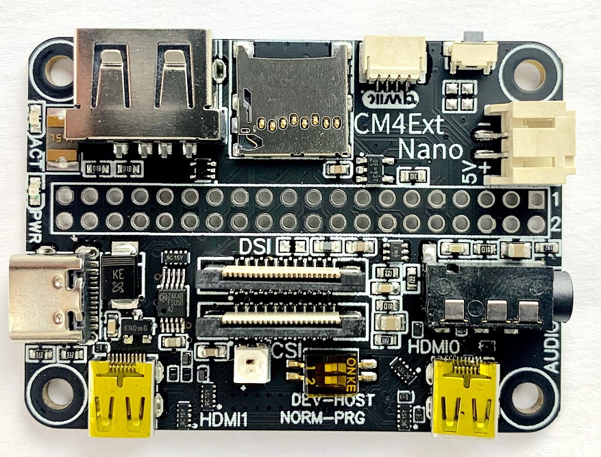
CM4Ext Nano is the world's smallest baseboard for Raspberry Pi Compute Module 4. Measuring only 55x40mm, it brings power of Raspberry Pi 4 to a slightly bigger footprint that Raspberry Pi Zero. It's compatible with all Compute Modules 4 boards, including eMMC and no eMMC versions.
- High denstity Raspberry Pi CM4 connectors
- 2x micro HDMI (type-D) connectors with ESD protection
- USB2.0 host connector with ESD protection and polyfuse
- USB-C connector for power and data with ESD and surge protection
- Micro SD card connector
- Act and Power LEDs
- 4-lane 22-pin DSI display connector
- 4-lane 22-pin CSI camera connector
- 40-pin GPIO connector
- WS2812 RGB LED
- Qwiic-Compatible 3.3V i2c connector
- 2-pin 5V connector for power in/out
- 3.5mm audio jack connector
- User button
- Two position DIP-switch for boot mode and USB configuration
CM4Ext Nano uses Hirose DF40C-100DS-0.4V connectors. This connector utilizes a locking system that prevents accidental unmating issues and emits a clear tactile click to ensure that mating has been completed. When mated, stack height (distance between CM4 and CM4Ext Nano) is 1.5mm.
Note: DF40 series connectors are specified for 30 mating cycles.
USB-C connector serves two roles: power supply for CM4Ext Nano and USB2.0 device data communication.
Two 5.1K resistors on CC1/CC2 lines to ground implemented onboard to claim 1.5A power per USB-C PD. USB2.0 PD modes are not supported and host PC or external power supply must be able to provide sufficient current.
Raspberry Pi CM4 can act as USB2.0 device to flash OS image on CM4 eMMC. Alternatively, CM4Ext Nano can be connected to host PC and provide such functionality as:
- Ethernet adapter, i.e. ssh connection to CM4 via USB
- Mass Storage device (CM4 acts as USB stick drive)
- Human Interface Device, where CM4 can send keystrokes to host system
Please refer to Raspberry Pi documentation to enable and use these modes.
CM4Ext Nano has two LEDs that work exactly the same as ones on Raspberry Pi 4:
- Green Activity LED
- Red Power LED
USB2.0 host connector has ESD protection on data lines and 0.75A polyfuse to limit power consumption of connected devices. CM4 has one USB2.0 bus that can be switched between USB-C and USB-A connectors. Thus, to enable USB-A port:
- Flip DIP-switch to HOST position
- Edit
/boot/config.txtfile to add following line:dtoverlay=dwc2,dr_mode=host
Micro SD card, same as for Raspberry Pi 4 boards.
Important! Don't insert SD card if using CM4 with onboard eMMC.
Four pin Qwiic-Compatible 3.3V i2c connector exposes i2c bus (GPIO2 and GPIO3 pins) and 3.3V power. It can be used to connect:
- Sparkfun QWIIC i2c modules
- Seeed Grove modules (only 3.3V, Grove i2c or Grove digital types via adapter cable).
- Your own extensions
Important! 3.3V is directly connected to CM4 regulator output and maximum current draw is 500mA. Exceeding maximum current consumption can permanently damage CM4.
5V connector directly routed to CM4Ext Nano 5V rail (i.e. same as 5V on GPIO and USB-C connectors). It can be used in to ways:
- Supply power to CM4Ext Nano
- Supply power to external boards, for example LCD display
Important! DO NOT connect external power supply via 5V and USB-C connector at the same time. Doing so can permanently damage CM4 and/or CM4Ext Nano.
Important! Connectors with pre-crimped wires are available from different suppliers. Before using those make sure that polarity is correct. If not, you can lift retaining clips on connector, pull out wires and swap them to keep color coding correct.
3.5mm audio jack connector can be used to connect headphones. Microphone input or composite video output on 4th pin is not implemented.
By default audio output is not enabled. To enable, edit /boot/config.txt to add dtoverlay=audremap,pins_12_13
Note: audio output is using GPIO12 and GPIO13. Those are not available for user when audio jack is enabled.
User button connected to GPIO4 and pulls it to ground when pressed, i.e. readout as logic 0. To use, configure GPIO4 as input with pull-up enabled.
CM4Ext Nano has two micro HDMI (type-D) connectors with ESD protection and 5V current limiter.
DSI display connector is 22 pin 0.5mm pitch flex cable connector. It has the same pinout and connector type as DSI connector on Raspberry Pi CMIO boards (CM1, CM3 and CM4) with exception of having GPIO9 on unused pin for interrupt line if using LCDs with touchscreen. Official Raspberry Pi 7'' LCD can be connected using adapter for CM1 CMIO (order code: CM1 Adaptors) or CM3 CMIO (order code: RPI CMDK ADAPTER) boards. As of Q1 2021, CM1 Adaptors available via RS Components (RS Stock No.: 136-3742 Mfr. Part No.: CM1 Adaptors)
Tested displays (via adapters):
Pinout:
| Pin | Name |
|---|---|
| 1 | GND |
| 2 | DSI1_D0_N |
| 3 | DSI1_D0_P |
| 4 | GND |
| 5 | DSI1_D1_N |
| 6 | DSI1_D1_P |
| 7 | GND |
| 8 | DSI1_C_N |
| 9 | DSI1_C_P |
| 10 | GND |
| 11 | DSI1_D2_N |
| 12 | DSI1_D2_P |
| 13 | GND |
| 14 | DSI1_D3_N |
| 15 | DSI1_D3_P |
| 16 | GND |
| 17 | GPIO9 |
| 18 | nc |
| 19 | GND |
| 20 | SCL0 |
| 21 | SDA0 |
| 22 | 3.3V |
Important! There are 22pin to 15pin flex cables available to interface Raspberry Pi Zero with Raspberry Pi camera. These cables have different pinout and won't work for DSI.
Important! When connecting Raspberry Pi display, always connect 5V power. SDA and SCL signals are connected via DSI display and there is no need to connect those with jumper wires.
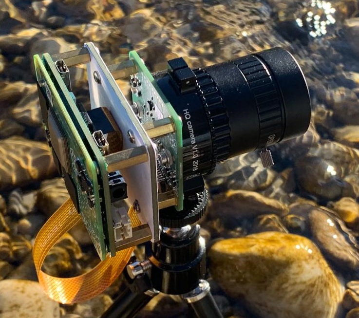
CSI display connector is 22 pin 0.5mm pitch flex cable connector. It is the same as on Raspberry Pi Zero and Raspberry CMIO boards. Flex cables are available from different suppliers as Raspberry Pi Zero camera 22 to 15 pin flex cable.
Pinout:
| Pin | Name |
|---|---|
| 1 | GND |
| 2 | CSI1_D0_N |
| 3 | CSI1_D0_P |
| 4 | GND |
| 5 | CSI1_D1_N |
| 6 | CSI1_D1_P |
| 7 | GND |
| 8 | CSI1_C_N |
| 9 | CSI1_C_P |
| 10 | GND |
| 11 | CSI1_D2_N |
| 12 | CSI1_D2_P |
| 13 | GND |
| 14 | CSI1_D3_N |
| 15 | CSI1_D3_P |
| 16 | GND |
| 17 | CAM_GPIO |
| 18 | nc |
| 19 | GND |
| 20 | SCL0 |
| 21 | SDA0 |
| 22 | 3.3V |
CM4Ext Nano has two position DIP switch for configuring USB and boot of CM4.
- DEV-HOST switch controls USB multiplexer. In DEV position CM4 USB port connected to USB-C connector. In HOST position – to USB-A connector
- NORM-PRG switch controls nRPIBOOT pin of CM4. In PRG position it's pulled low, forcing boot from an RPI server (boot from PC or another Raspberry Pi to flash eMMC). In NORM position boots normally.
GPIO connector is standard 40 pins 2 rows 2.54mm pitch pin header capatible with Raspberry Pi GPIO connector. Due to tight space avaialble for PCB layout, it was moved from board edge. When delivered, GPIO connector is not soldered to save several millimeters in height for those who building compact projects. If soldering GPIO header, use included soldering spacer and put it between board and header connector.
Pinout:
| Name | Pin | Pin | Name |
|---|---|---|---|
| 3.3V | 1 | 2 | 5V |
| GPIO2 | 3 | 4 | 5V |
| GPIO3 | 5 | 6 | GND |
| GPIO4 | 7 | 8 | GPIO14 |
| GND | 9 | 10 | GPIO15 |
| GPIO17 | 11 | 12 | GPIO18 |
| GPIO27 | 13 | 14 | GND |
| GPIO22 | 15 | 16 | GPIO23 |
| 3.3V | 17 | 18 | GPIO24 |
| GPIO10 | 19 | 20 | GND |
| GPIO9 | 21 | 22 | GPIO25 |
| GPIO11 | 23 | 24 | GPIO8 |
| GND | 25 | 26 | GPIO7 |
| GPIO0 | 27 | 28 | GPIO1 |
| GPIO5 | 29 | 30 | GND |
| GPIO6 | 31 | 32 | GPIO12 |
| GPIO13 | 33 | 34 | GND |
| GPIO19 | 35 | 36 | GPIO16 |
| GPIO26 | 37 | 38 | GPIO20 |
| GND | 39 | 40 | GPIO21 |
Important! Soldering spacer MUST be used when populating pin header connector. Without it, pins would pop on the other side of the board and will permanently damage CM4 board mechanically on mating.
Note: Raspberry Pi HATs are expected to work normally with correct dt-blob, ie dedicated i2c bus (ID_SC and ID_SD) must be enabled.
WS2812 is connected to GPIO10 pin.
Summary below is based Adafruit tutorial with CM4 specific settings:
- Enable SPI, using
sudo raspi-configand navigating toInterface Options-SPI-Yes - Edit
/boot/config.txtto addcore_freq_min=500and reboot - Install Python libraries:
sudo pip3 install rpi_ws281x adafruit-circuitpython-neopixel - Test with following code:
import board
import neopixel
pixels = neopixel.NeoPixel(board.D10, 1, pixel_order="GRB", brightness=0.2)
pixels[0] = (0, 255, 0)
Raspberry Pi CM4 has one USB2.0 port. It can be configured as USB host or USB device. To support this functionality, CM4Ext Nano implements USB switch to route USB D+/- lines to either USB-A or USB-C connectors. It controlled by DIP switch:
- in DEV position USB D+/- lines routed to USB-C connector and CM4 USB_OTG_ID pin is floating (pulled up on CM4 internally)
- in HOST position USB D+/- lines directed to USB-A connector and CM4 USB_OTG_ID pin is pulled low
This DIP swich only affects data lines, while power routing remains the same, i.e. when configured as USB device, data lines switched to USB-C connector, but there is still 5V available on USB-A connector.
Software wise, USB configuration is done using device tree overlays in /boot/config.txt file.