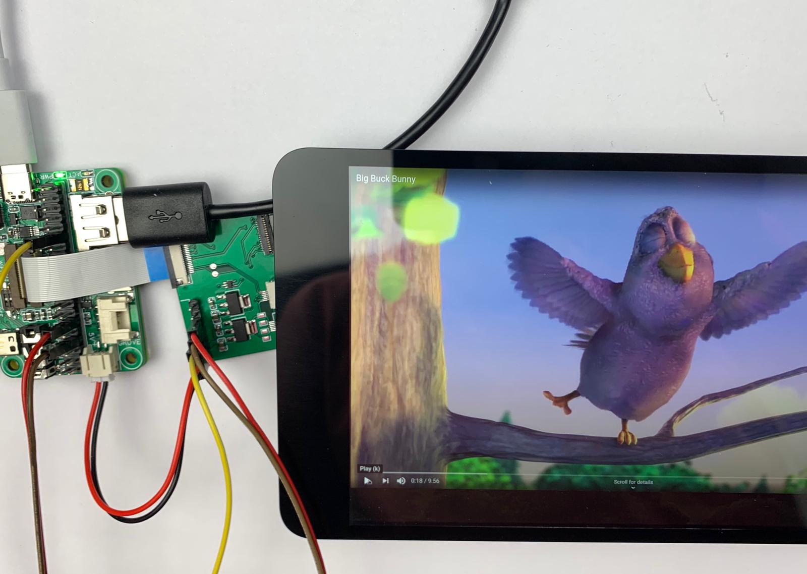
Raspberry Pi CM4 bindings for JDI LT070ME05000 1200x1920 IPS display
Status: Adapter board V2 prototypres are manufactured. Let us know if you'd like to order it with CM4Ext Nano
Adapter board V2 with CM4Ext Nano
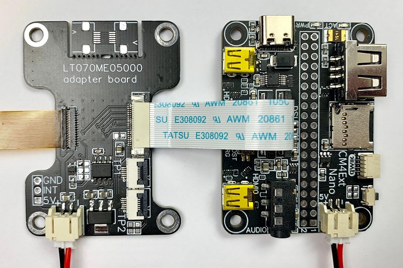
Adapter board V2 requires only 22 pin DSI cable and +5V power:
- i2c GPIO expander eliminates need for 3 GPIO jumper wires
- 3.3V LDO removed, as panel can operate from 5V
JDI LT070ME05000 is 7" 1200x1920 4-lane DSI IPS display used in Asus/Google Nexus 7 2013 tablet. To use it, 4-lane DSI interface is required, so it can be used with Raspberry Pi Compute Modules 3 and 4. Some suppliers have these displays available from ~$US20 shipped. There is a driver for this panel in a mainline already included, so we only need to compile/install it and make device tree overlay
We need build rpi-5.10.y branch with LT070ME05000 module enabled. This is well documented at Raspberry Pi help pages here and here
sudo apt install git bc bison flex libssl-dev make
sudo apt install libncurses5-dev
git clone --depth=1 --branch rpi-5.10.y https://github.com/raspberrypi/linux
cd linux
KERNEL=kernel7l
make bcm2711_defconfig
make menuconfig
Navigate to Device Drivers/Graphics support/Display panel, check JDI LT070ME05000 panel and save
Now we need to build and install kernel:
make -j4 zImage modules dtbs
sudo make modules_install
sudo cp arch/arm/boot/dts/*.dtb /boot/
sudo cp arch/arm/boot/dts/overlays/*.dtb* /boot/overlays/
sudo cp arch/arm/boot/dts/overlays/README /boot/overlays/
sudo cp arch/arm/boot/zImage /boot/$KERNEL.img
Device Tree Source can be modified to assign another GPIO numbers, then compiled and copied to boot partition:
sudo dtc -@ -I dts -O dtb -o vc4-kms-dsi-lt070me05000.dtbo vc4-kms-dsi-lt070me05000-overlay.dts
sudo cp vc4-kms-dsi-lt070me05000.dtbo /boot/overlays/
Then edit /boot/config.txt to add:
lcd_ignore=1
dtoverlay=vc4-kms-v3d
dtoverlay=vc4-kms-dsi-lt070me05000
and reboot
After reboot screen should we working and have portrait orientation. To adjust, use Main Menu/Preferences/Screen configuration utility
LCD pins defaults to:
- Reset - GPIO17
- Enable - GPIO4
- DCDC Enable - GPIO5
Default pins can be changed, for example:
lcd_ignore=1
dtoverlay=vc4-kms-v3d
dtoverlay=vc4-kms-dsi-lt070me05000,reset=5,enable=17,dcdc-en=4
Proof-of-concept schematics
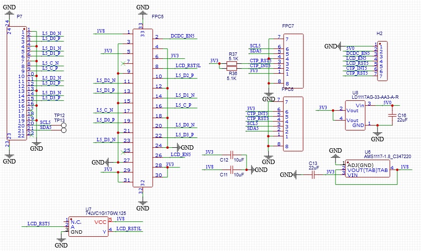
Important notes:
- This schematics comes with no warranties, use at your own risk
- Verify pin 1 location for your application: two FPC connectors facing each other would have first pin at opposite side
- 3V3 LDO gets hot. According to datasheet, VDD and VDDp can actually be powered from 3.0-5.0V
- i2c part for TP is not tested
- LCD_RST MUST be 1.8V with sufficient current, ie resistive divider 3.3->1.8 is likely not to work. If using with RPi CM3, LCD_RST can be directly driven by 1.8 powered GPIO bank