Something I've wanted for quite a while is a clock I can plug in and have it always displaying the right time. Most people just buy an "atomic clock" for this purpose but there are several problems with those. They typically receive an amplitude-modulated time code from WWVB. Propagation of this signal to the east coast of the US is pretty much nonexistent and gets buried under the RF noise that is especially strong here, so these clocks rarely successfully synchronize and thus are usually wrong. NIST attempted to fix this by using a new phase-modulated timecode in addition to the traditional amplitude-modulated code, with excellent results... except that I can only find one clock and no receiver modules on the market that receive the new signal. The only practical way to receive the code is to build your own which is quite the undertaking. Even then, you still have to calculate the propagation delay from Fort Collins, CO to actually have an accurate clock, at least if you care about milliseconds.
With that in mind, NTP seems like the way to go. If the Internet is up, you can synchronize your clock without a radio signal. I have some applications in mind that require more than the millisecond or so of accuracy that NTP provides, though, so I decided to use a timing GPS to get that millisecond down to the microsecond range. We can use both NTP and GPS to provide some ability to failover in the event that the Internet is not available, or we don't have a good GPS signal. The end result will be a clock that doesn't need to be set, and is useful for experiments like calculating HF propagation paths. Fun stuff!
To control everything, I decided on a BeagleBone Black. This was because I happened to have one around waiting for an application. It is overkill for this application, but it's a generally solid device and I prefer it over the Raspberry Pi in general. It has more capability and it doesn't involve Broadcom, a true win-win situation. You could also use a microcontroller. You don't really need a full Linux box to do something this simple, but full Linux boxes are easy to use and already include multiple working NTP implementations. For example, I wrote all the code for this project in Emacs on the clock itself. Yeah, the clock has Emacs on it.
Also in the junk box, I happened upon a Resolution T Timing GPS and a very convenient breakout board to power it and break out the UART and PPS signals to a standard pin header. What a junk box. We will be using the UART time signal to get a 1-second accuracy time and date, and the PPS signal to read the start of the second to within 10 nanoseconds.
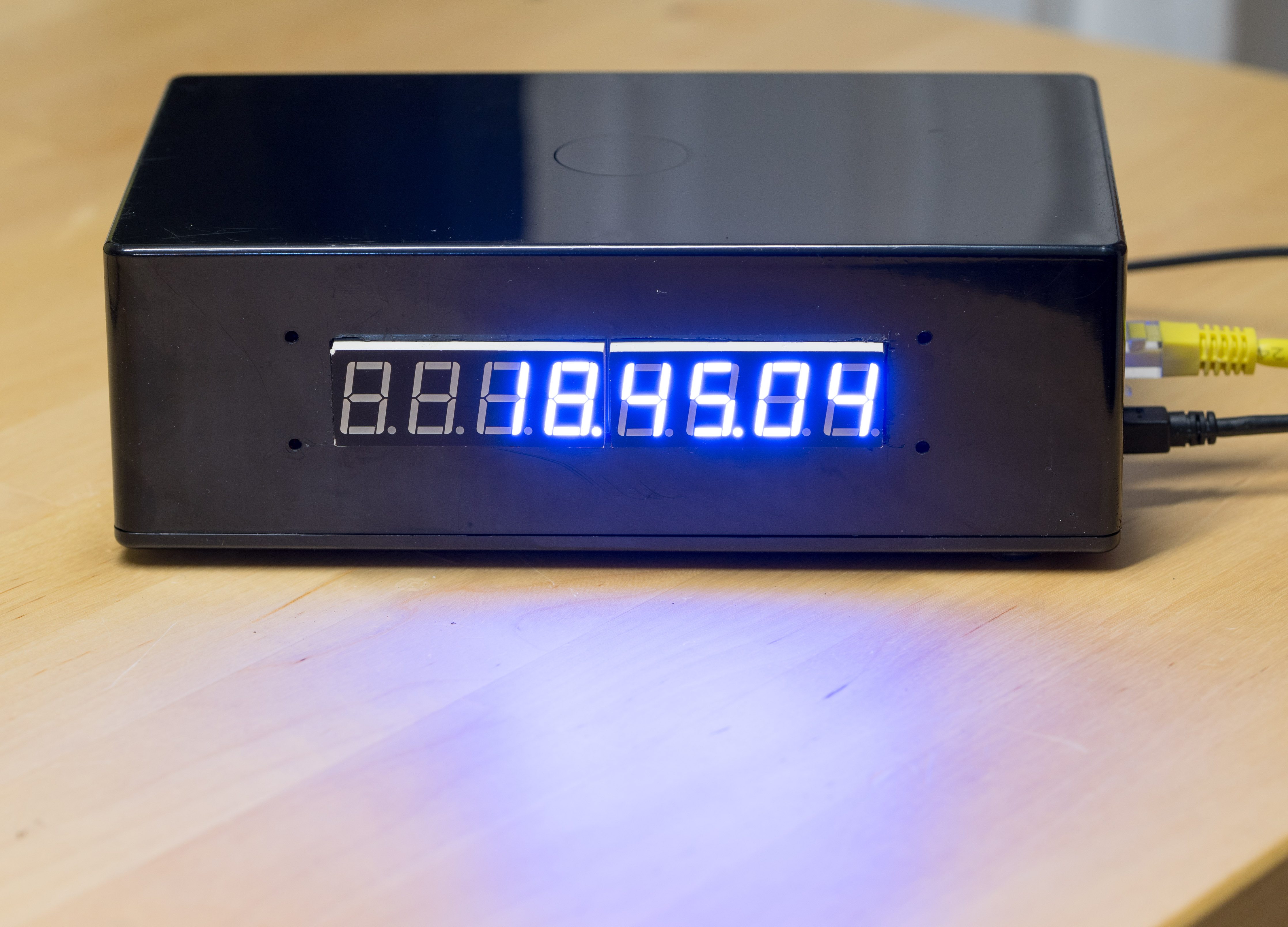
To display the time, I looked around for some sort of self-illuminating screen. The currently-available OLED displays are very beautiful, but not big enough to see across the room. VFDs are pretty nice, but expensive at large sizes. So I went with a simple MAX7219-based 7-segment LED display I found on Tindie. It's a compromise, it's not really big enough, but it gets the job done and it's priced reasonably. (Be aware that the MAX7219 is a 5V device, not a 3.3V device, and the datasheet claims that a logic high is 4V minimum which you cannot produce with the BeagleBone. However, it seems to work fine on 3.3V.)
Finally, I picked up a random project box, some M2.5 standoffs and screws, and some rubber feet to encase the finished clock, along with a 5V GPS puck antenna.
With all the parts procured, it was a matter of wiring everything up. I used jumper wires to wire everything together, with some housings to make clean wiring harnesses.
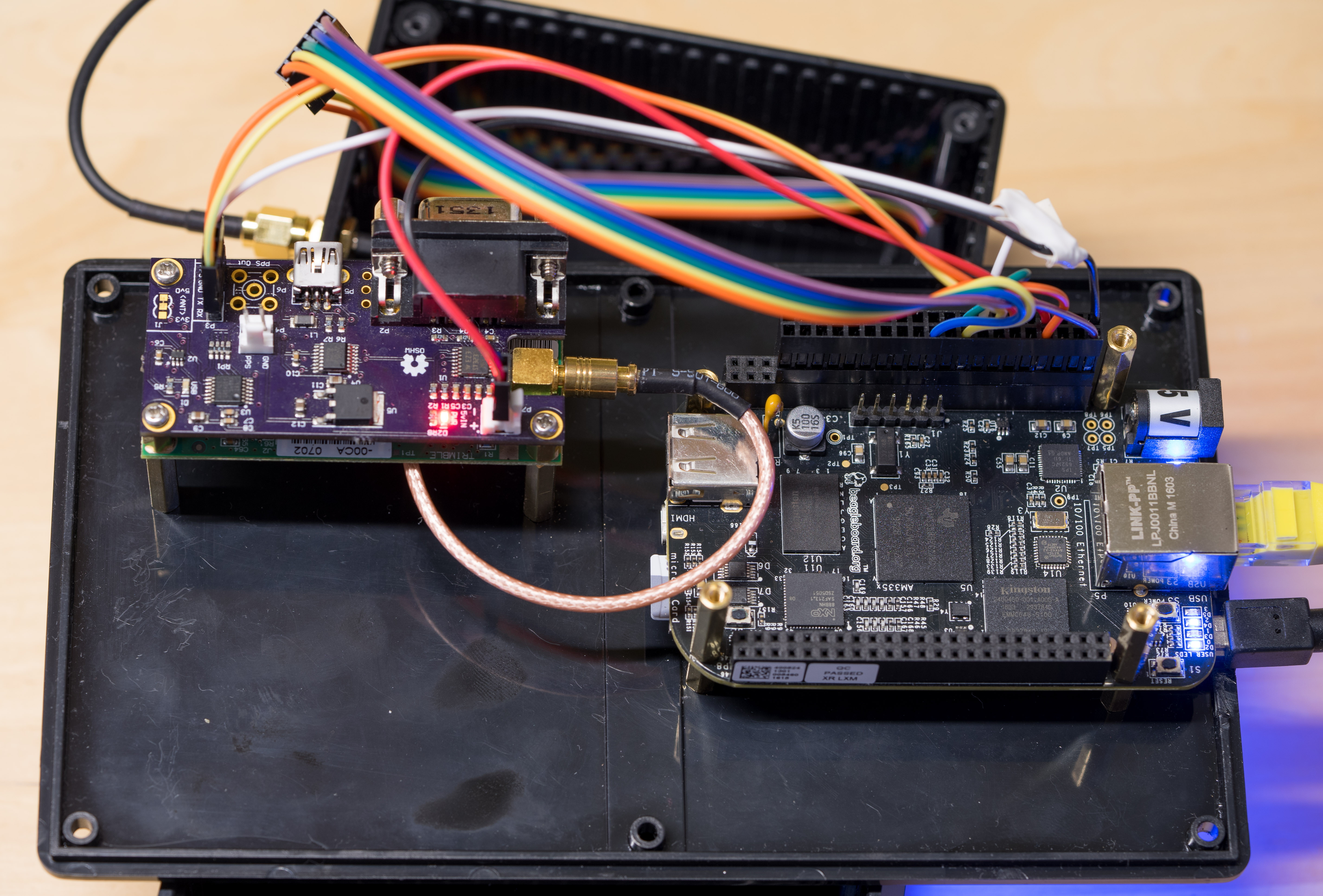
The GPS and display are powered from the BeagleBone's SYS_5V rail. The UART
link to the GPS goes to the BeagleBone's UART4 pins (TX and RX only, I'm not
using any other UART signals), and the GPS's PPS output to GPIO_48. The PPS
signal is "terminated" with a 50 ohm resistor, more to drop the voltage below
3.3V than to actually impedence-match the transmission line. I'm not sure you
can call some random wires a transmission line. Finally, the BeagleBone's
SPI0 bus connects to the display.
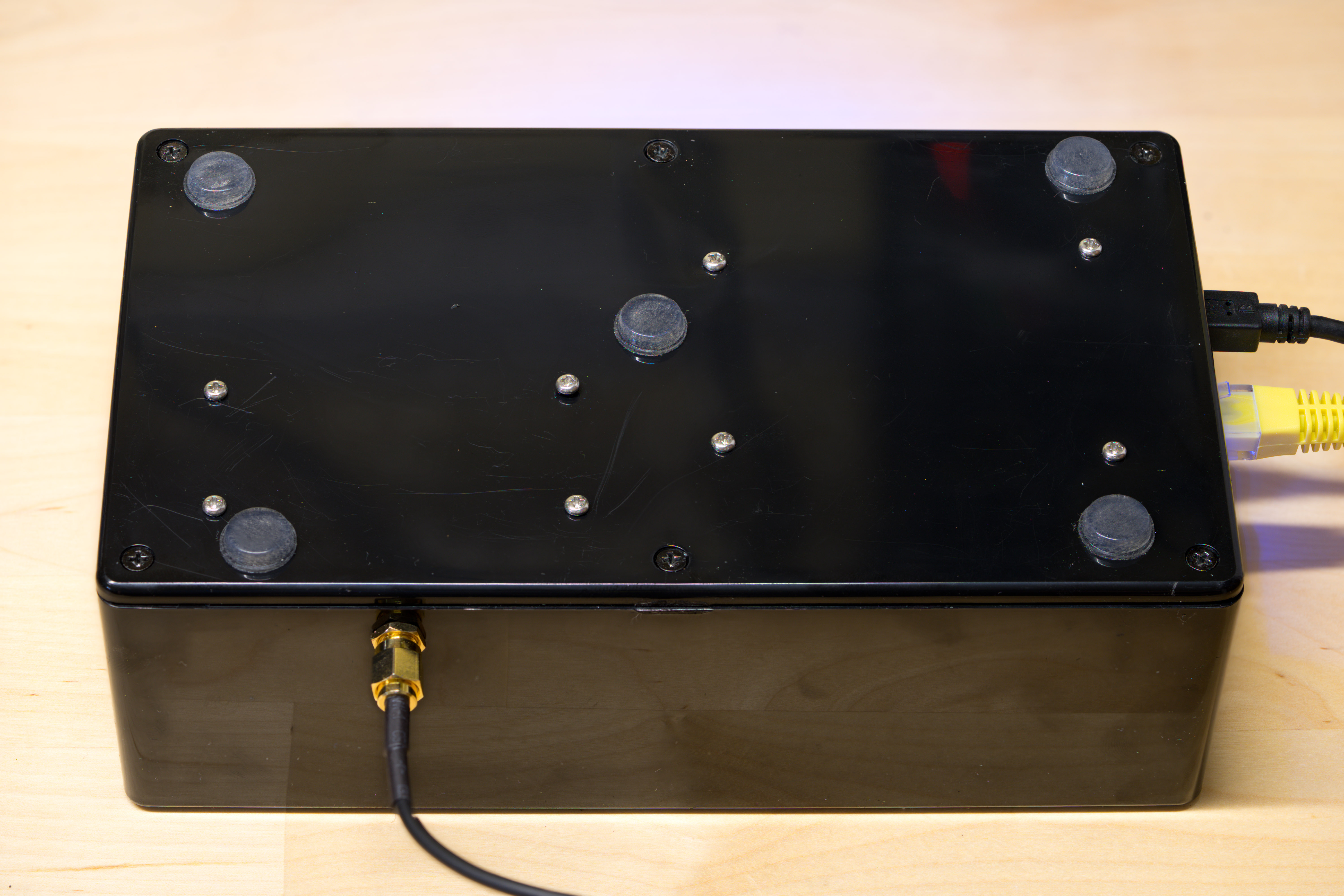
I drilled holes for the Beaglebone and Resolution T mounting holes (using each device as a template, probably not the best idea if you care about your expensive electronics), and mounted each device with standoffs and screws through the bottom of the case. They're not going anywhere!
For the display, I very carefully measured my LED board and made some markings with a scribe (actually the edges of my caliper). I then drilled out the corners with the largest drill bit I had on hand. Then I connected the dots with a hacksaw. The lines were not straight, so I cleaned them up (after much debate) with an old pair of side-cutters. They still weren't straight so I filed them down. This was not an enjoyable process and I recommend doing it any other way. The Internet says to just buy a laser cutter and use that. Maybe next time.
The display then goes through the hole and stays in place with friction. I drilled four holes to screw the display in, but my assumption that the display was mounted in the dead center of the board was wrong by a few millimeters and thus the holes do not align. Measure more than 0 times, cut once, folks.
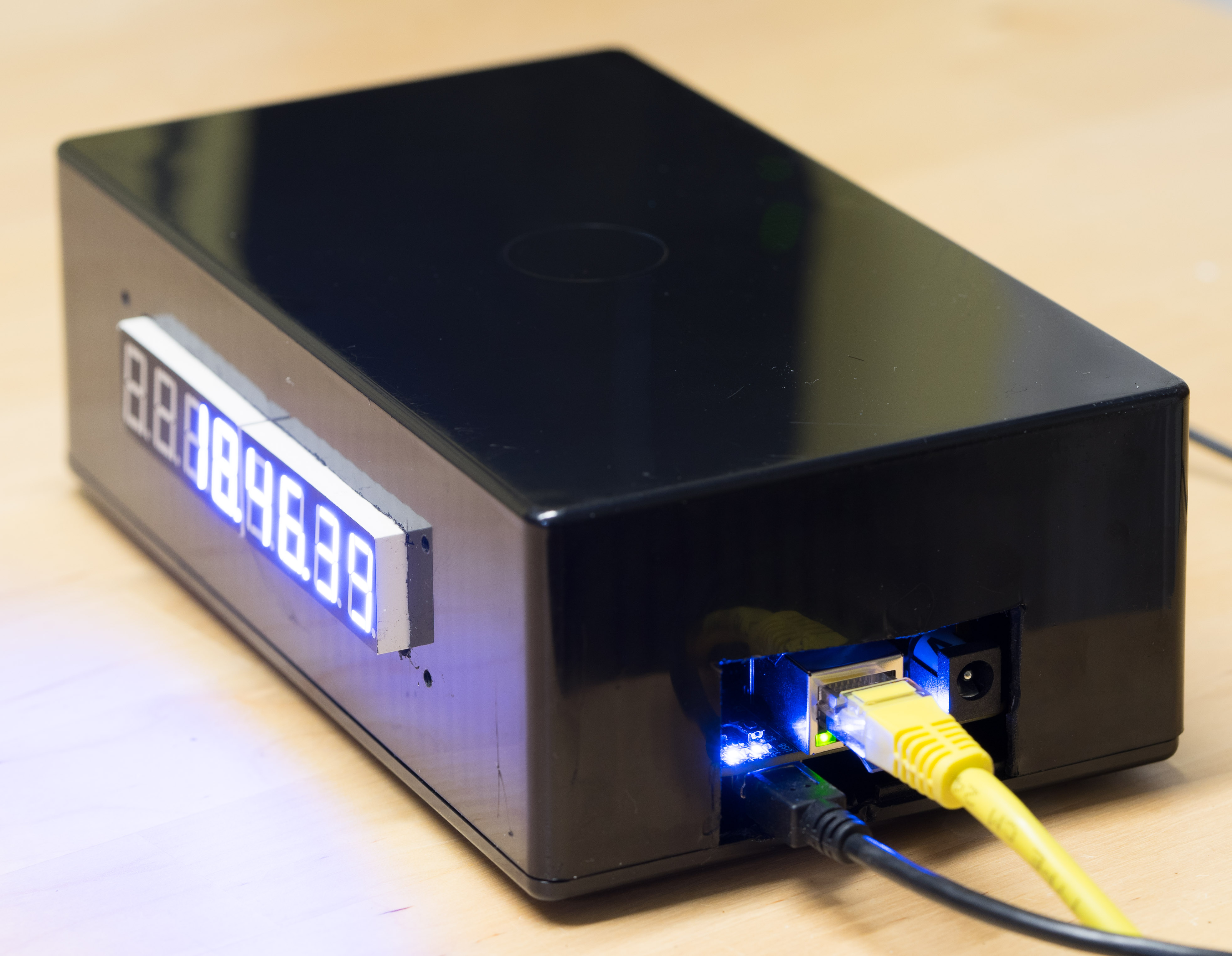
Next, I cut out a hole for the Ethernet cable and power input on the side. This was perhaps even less enjoyable than cutting the hole for the display, because I just eyeballed it and took to the plastic with side-cutters. The result was as good as you'd expect. Not very! If you are looking for advice on how to build enclosures, I recommend asking anyone other than me.
Finally, I drilled a hole for the SMA connector to the GPS antenna and screwed the connector in. Whenever you have an SMA connector on your device, you know you're doing something cool. I'm pleased!
Now that you have all this clock-like hardware, you actually need to interface
it to software. I assume you have some recent Debian running on your
BeagleBone. If you don't there are other tutorials that can get that going for
you. (From the provided images, I updated the kernel to the latest version,
4.14.24-ti-r37 at the time of this writing. I don't believe you need to do
this for the clock; I was playing with some i²c displays that needed a more
recent kernel to use them as framebuffer devices.)
By default, the BeagleBone boots with a "universal overlay", which lets you
configure which pins do what at runtime with the config-pin utility. This is
fine and nice if you just want to write a Python script to read GPIOs or
whatever, but not fine if you want to use kernel drivers to interface with your
hardware.
To do that, you have to disable pinmuxing, setup your pinmux manually, and then add your devices to the device tree. I spent about two weeks figuring this out, eventually realizing that all the documentation was wrong, and just reading source code and messing around until it worked. I guess I should write some of that up. Everything you read on the Internet about device tree overlays is wrong (they were right when the BeagleBone used a proprietary runtime device tree overlay, but it now uses uBoot to load the device tree). Just use the bb.org-overlays repository as an example, but keep in mind that many of those overlays don't work either because they don't disable pinmuxing first. So I guess just follow the example in my repository, which does work but probably cargo-cults some bad habits. (For example, I don't believe you need to number the fragments as every example ever does. This isn't BASIC, you don't have to number the lines for the computer.)
Anyway, we set the UART pins to be a UART, the GPIO pin to interface with the
kernel PPS driver, and
the SPI pins to be a generic spidev running at 10MHz (per the MAX7219's
datasheet). We will handle the display from userspace, but let the kernel
handle synchronizing with the GPS's pulse per second signal. This yielded less
jitter than using a userspace PPS watcher like
rpi_gpio_ntp. The jitter from the
kernel driver is on the order of a microsecond, the jitter from userspace is on
the order of 500
microseconds. So
it's worth taking the time to use the kernel driver. (Keep in mind that you're
still throwing away 2 orders of magnitude of precision versus what the GPS can
provide. Linux is that bad for real-time applications.)
Once you compile the overlay, copy it to /lib/firmware, edit /boot/uEnv.txt
to load the overlay, and reboot, you'll have /dev/pps0 for the PPS signal,
/dev/ttyO4 for the GPS UART, and /dev/spidev0 for the SPI bus. In the
repository is a udev rule to make the serial port appear as /dev/gps0 for
convenience.
Now that Linux can talk to all the hardware, it's just a Simple Matter Of Programming to make it all work. I spent a long time at this stage because there are many paths you can take.
The easy part is the display. I wrote a simple go program to update the display every second. It works fine. The repository contains the necessary systemd rules to start it when you boot, as well.
The hard part is getting the GPS time. You can use ntpd or you can use chronyd. You can have ntpd read the time from the serial port itself, or you can get gpsd to do it and send the result to your ntp daemon. There are two protocols gpsd can use to do this.
ntpd contains at least three different drivers that purport to read TSIP (my
GPS's binary wire format) but none of them work with my exact GPS, and none of
them take advantage of any data offered in the binary wire format. They won't
disable the source if the GPS loses its lock or goes out of Overdetermined Clock
mode. They don't read and correct the GPS's clock quantization error. So there
is no point in using them. They are completely unconfigurable (down to not
being able to specify the baud rate of the serial port, or even when /dev
entry to use as the serial port), are probably unmaintained and will never work
again, and don't do anything that would be useful.
I eventually decided, after much source code browsing and some programming, to just use gpsd speaking over the SHM interface to chronyd. (I had had quite enough of ntpd at this point, and ended up choosing chronyd because it will more aggressively slew the clock when the device reboots, has a cleaner configuration format, has less features, and provides a lot of very helpful debugging output. But also out of pure spite for ntpd's code.)
gpsd does not really fit with my software engineering philosophy of being simple and configurable. Rather, it magically tries to determine everything itself, with varying results that usually involve hanging for several seconds as it tries to autobaud by looping through a list of possible baud rates, writing random binary to your serial port, and praying for a response. Hey, an unknown device! Let's write random data into its memory! That ought to be reliable! You know guys, we have something called config files and command-line arguments, where the user who intimately knows the exact details of their GPS could just pass in that information. But sure, write thousands of lines of code to waste several seconds guessing, I guess, if that's how you want to spend your spare time. In the end, it works, which I suppose is better than something that doesn't work. The gpsd project also has a very thorough writeup on how to interface it with NTP for timing purposes. Good document.
Anyway, edit some config files and chronyd will know the GPS time (actually corrected by my GPS to UTC time, and it knows this) and when each second starts via the kernel pps driver. Excellent.
All the configuration is in the repository, including the /etc/default entry
for gpsd, some systemd overrides to ensure that chronyd and gpsd start in the
right order, and the chronyd configuration itself.
At some point I was just going to skip gpsd and write my own TSIP interface,
that work is in the
trimble
directory of this repository. I decided that we already have too much error
introduced by the kernel interrupt-handling latency for an application of the
GPS's quantization error to be worthwhile enough to write more code. So gpsd
it is, and it works. But someday, I want my nanoseconds instead of mere
microseconds.
At this point, you can restart the device and the correct time will appear on the clock face.
Correct time, you say? How do you know? I don't actually have any way of measuring the correctness to the microsecond level, so it's all a leap of faith. The GPS sees satellites. chronyd can talk to the GPS. The GPS is configured to output UTC seconds (not GPS seconds, which, fun fact, happen at different times than UTC seconds). Maybe it will all magically work. Sometimes that happens, you know. In dreams.
I did tune into some time signals and compare my clock to the signal, and the results are excellent. I even made a video:
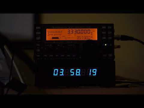
I get kind of poor WWV reception at my location but pretty good CHU reception, so you can watch that video and learn how to say "coordinated universal time" in French as an added bonus. Either way, time stations are super relaxing to listen to, with that nice 1Hz tempo. My kind of jams. Enjoy.
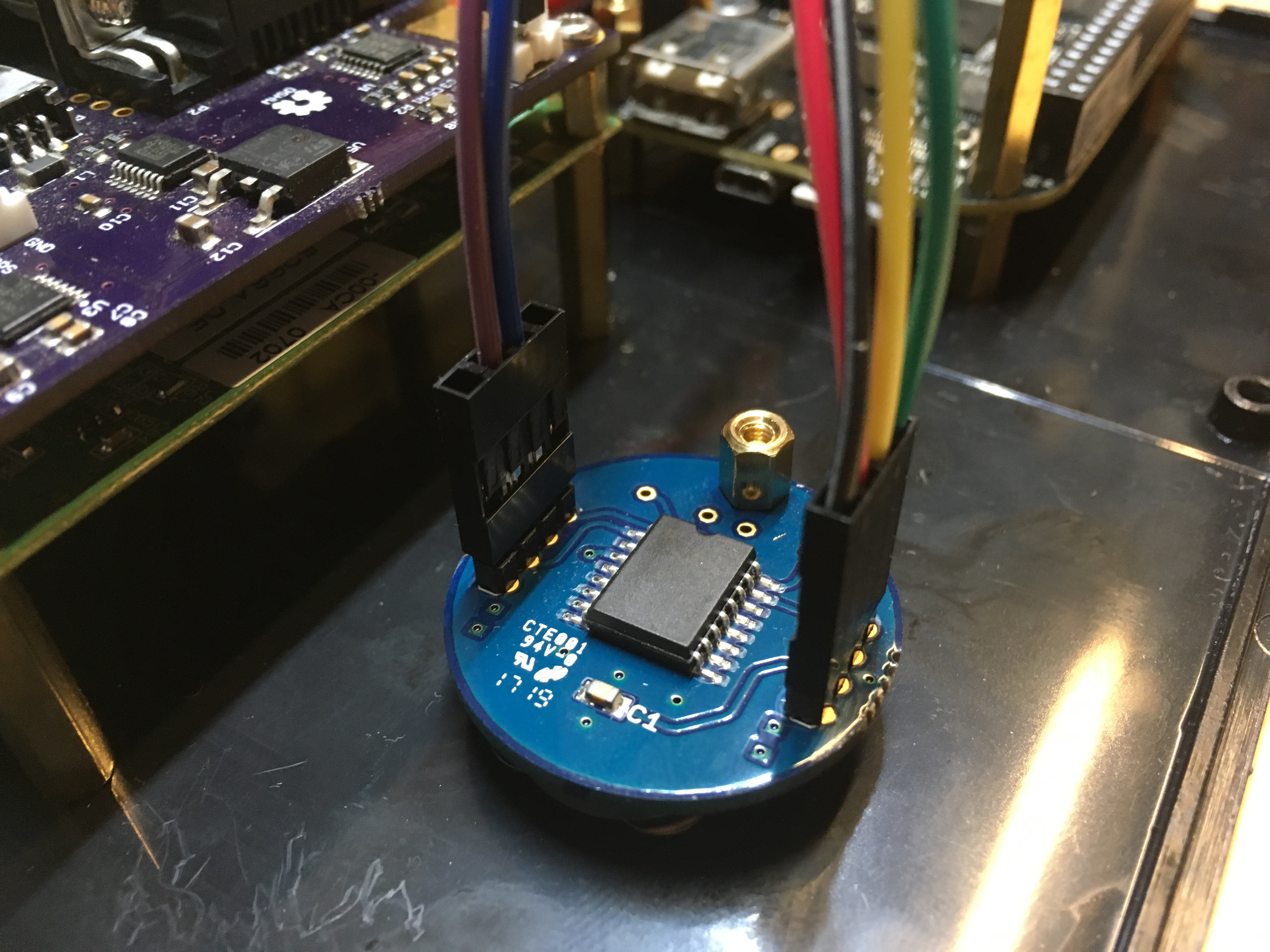
To get the time correct after a cold boot, I added a battery-backed real time clock to the i2c bus. This also has a PPS output, and while I don't trust it to be synchronized to UTC seconds, the frequency should be pretty accurate. So I have chrony monitoring its 1Hz SQW output, but not using it for time calculations. A device tree entry makes this clock the default hardware clock, so the time will be read from it upon a cold boot. It also measures the temperature inside the clock, which might look nice on graphs.
At some point, I learned how to 3D print things, and made a 3D-printed case that keeps the internals organized and the outside looking very clean. No more horrible hacksaw holes.
I also upgraded the display to a bunch of DotStar matrixes:
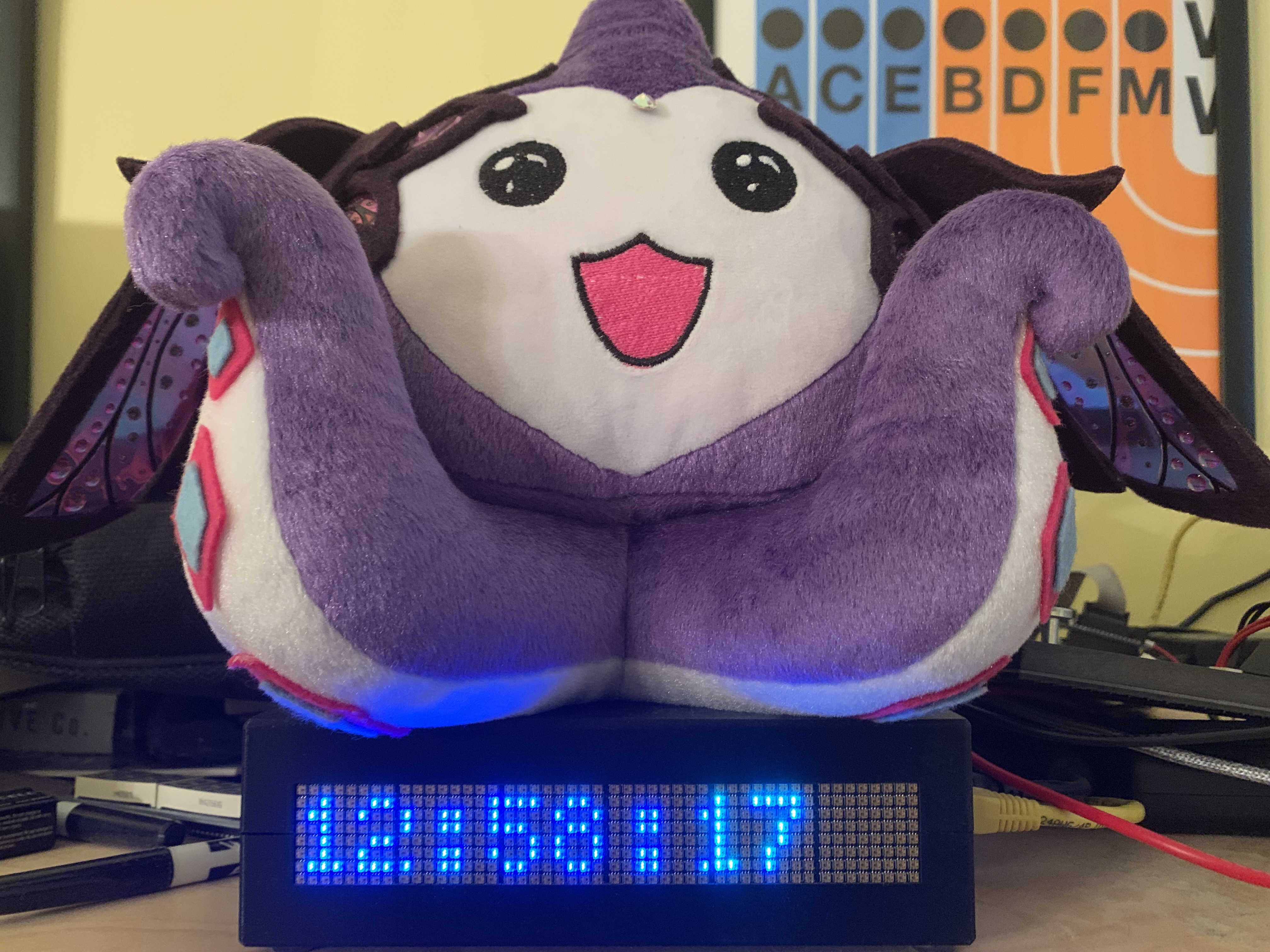
Those are driven over 3.3V SPI from a Go program (in the repo).
I'd like to get more than just microsecond accuracy, but convincing Linux to do this will be a chore. The BeagleBone has two embedded microcontrollers called Programmable Realtime Units which do in fact work in real time. You can read a GPIO pin once per 200MHz clock cycle, for example, which would let you read the PPS signal with a precision of plus or minus 5 nanoseconds, better than the GPS's precision of 10 nanoseconds. You can also read the serial port and apply the clock quantization correction. At that point, you would know exactly which clock cycle the UTC second started on, which is much more accurate than the current method.
As a compromise, I have some code in progress to kick the PRU at the beginning of each second as seen by the Linux kernel, and have the PRU output back to Linux the number of clock cycles elapsed between that signal and the GPS's PPS signal. This would at least let me make a nice-looking graph of the clock's drift (though might end up being a nice-looking graph of interrupt-handling latency).
The PPS signal actually gives you two pieces of information per second. When the signal rises, that's the start of the second. Exactly one millisecond later, the clock falls. If we read both of these edges, we would have twice as much data to work with, but we don't.
I would like to integrate other time signals that I can receive into the NTP calculation. I can pretty reliably receive CHU at night, WWV during the day, and hope to receive WWVB's phase-modulated signal in the future. With more time signal input, I can rely less on NTP servers for sanity-checking.
In the end, I wanted a clock I don't have to set that has a nice bright display. I now have one. Complete success!