Honeybee Die-Off is a a serious problem happening around the world. Honeybees which are indigenous to Europe and have been brought over to North America are dying off for a variety of reasons, namely 1) Lack of genetic diversity and robustness, 2) parasites, 3) harsh treatment or mistreatment 4) chemicals, among other potential reasons not listed here.
The objective of this project is to provide an easy way for honeybee farmers to cheaply and remotely monitor hives for incoming parasites, a major contributor to honeybee die-off. The actionable item for a commercial beekeeper, according to the University of Minnesota extension service, may be to treat a hive which is undergoing incoming mite infestation, to save a hive from further die-off. One of our hypotheses is that commercial bee-keepers will be highly concerned about mites being carried into the hive on the backs of bees who had visited other infested hives.
This Readme file is written as a general, "how-to," aimed at a DIY Hobby Electronics Audience for use with either at-home or commercial bee-hives.
Our primary objective is to give beekeepers the ability to remotely flag mite-infested hives for treatment.
This project uses an Arduino Yun to read data from a ACS712 current meter as well as a voltage divider to read directly from a 12V battery, which is powering the Yun itself via a USB output 12VDC/5VDC voltage converter.
https://www.arduino.cc/en/Main/ArduinoBoardYun?from=Products.ArduinoYUN
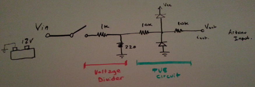
The circuit, as shown above, is a simple voltage divider followed by a TVS circuit, which uses standard IN4740 diodes. The IN4740 diodes were used due to their fast turn-on time, which are presumably faster than the Arduino Yun inrush diodes, whose turn-on time specifications could not be found.
http://www.avrfreaks.net/forum/clamping-diodes-0 http://www.mouser.com/ds/2/149/1N4740A-888332.pdf http://www.onsemi.com/pub_link/Collateral/AND8230-D.PDF
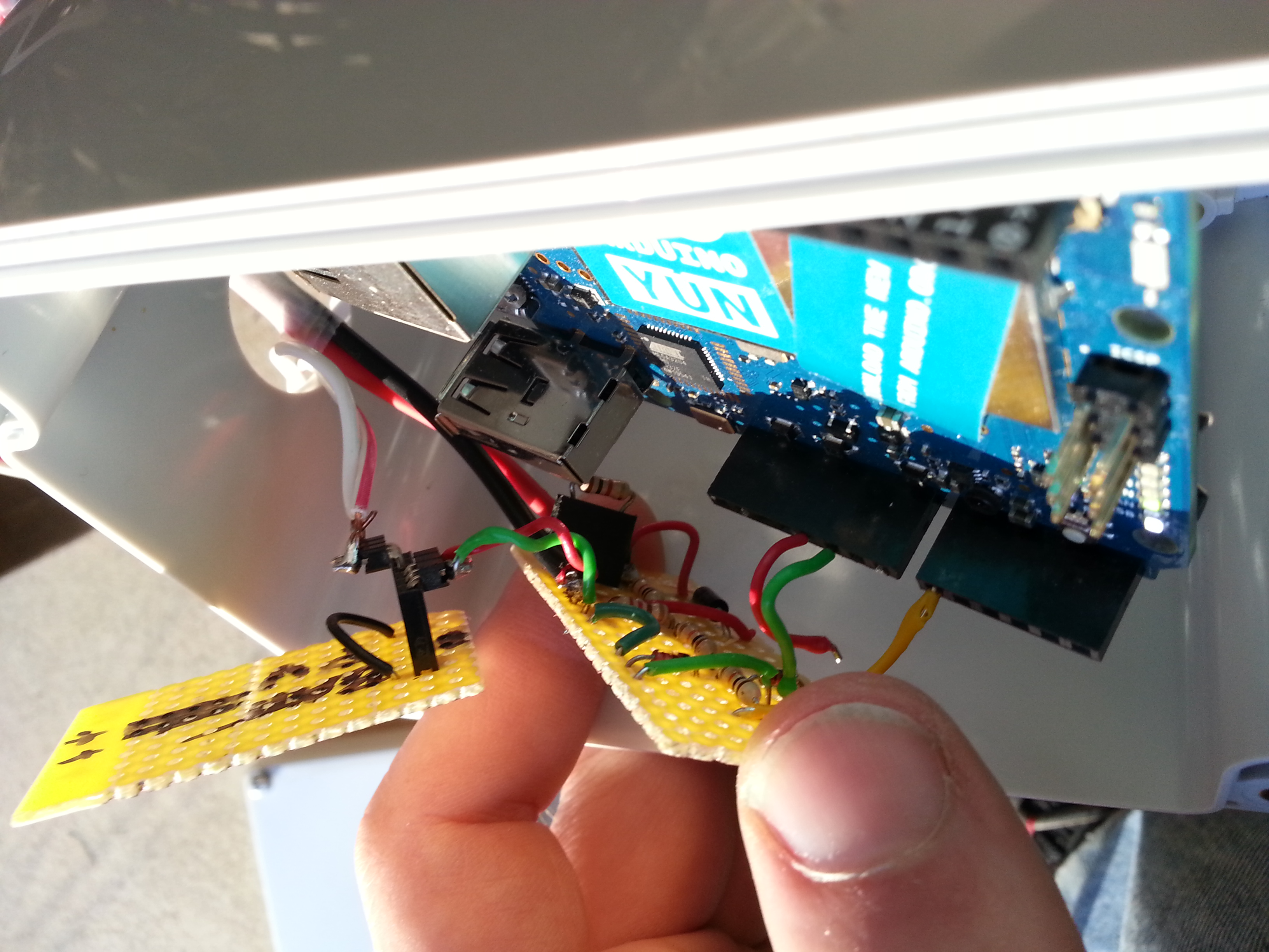
The above is a picture of the hand-soldered prototype of the circuit, which feeds into A0 in the Arduino Yun.

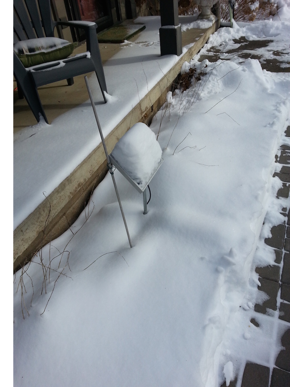
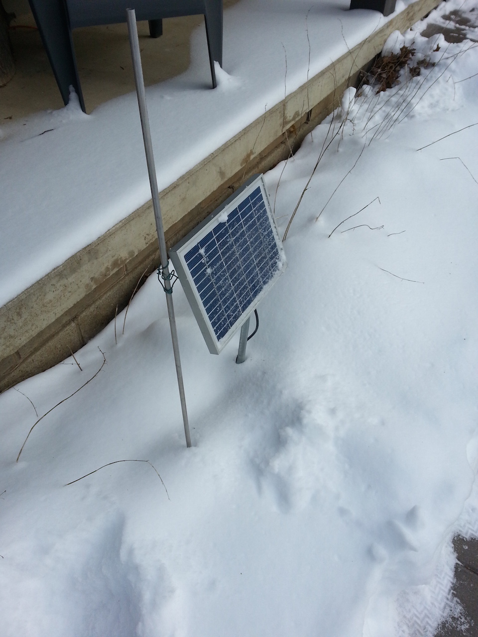
The above picture is a solar panel, which feeds into the enclosure box sitting outside.
Every 15 minutes, voltage is measured at the Arduino pin A0, which is mathematically translated from a 0-5V range to a 0-24V range using a scaling factor that was identified with a multimeter and power supply. The information is sent via the Yun's WiFi functionality to the ThingSpeak server via a POST method. The voltage ingformation is displayed on a ThingSpeak Channel chart, as shown in the below chart.
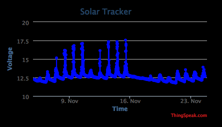
This functionality makes use of a couple of pre-built ThingSpeak functions included in ThingSpeak.h.
ThingSpeak Public Channel Link
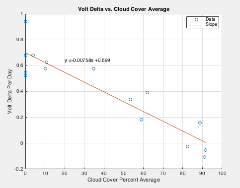
After sorting and structuring the data into, "time windows," we can identify the voltage at the, "start," of the "solar day," defined as when the sun starts hitting the solar panel, and the, "stop," of the "solar day," defined as when the sun no longer hits the solar panel. The difference between these voltages is the, "voltage delta." We can also read another ThingSpeak channel which is reading cloud cover for the region where the solar system is located, using a weather-reading API.
Plotting Cloud Coverage vs. Voltage Delta, we see a linear pattern. We also find that the anti-correlation is very close to 1. Therefore, we can solve for a linear regression model using Matlab's "" function, as shown on the below chart.
https://darksky.net/details/44.9773,-93.2655/2017-1-11/us12/en
There are advantages and disadvantages to having solar panels located in northern lattitudes. On the one hand, the colder weather increases semiconductor efficiency, meaning that the solar panel will produce more electrical power output given the same amount of isolation (light/irradience input power per meter squared). However, there is a risk of snow blanking out the solar panel.
From the standpoint of the learning model, having a snowfall signal does not automatically kill a solar panel's power output. If there is a snowfall, the snow could easily melt and fall/drip off of the solar panel, leading to a completely normal/open solar panel. However if the snowfall is followed by a brief melting and then subsequent sufficiently cold weather, the snow coating over the solar panel could turn into ice, and the cold temperatures will not allow the snow to melt - potentially leading to multiple weeks of no power output.
Practices that are recommended to prevent or minimize this from happening include angling the solar panel at a high angle with respect to the ground. E.g. the National Oceanic and Atmospheric Administration recommended solar angle for Minneapolis, Minnesota for example is around 45 degrees with respect to ground for optimal power absorption over a year. That being said, to avoid snow and ice build-up, it may be appropriate to consider a higher angle, say 50 or even 60 degrees, depending upon the context of the solar panel, to prevent snow and ice buildup.
From a learning model perspective, we can build in a function which looks for snowfall and subsequent lower temperatures, which then reports back to the on-site Arduino Yun, telling it to anticipate low power for the following 2-3 weeks.
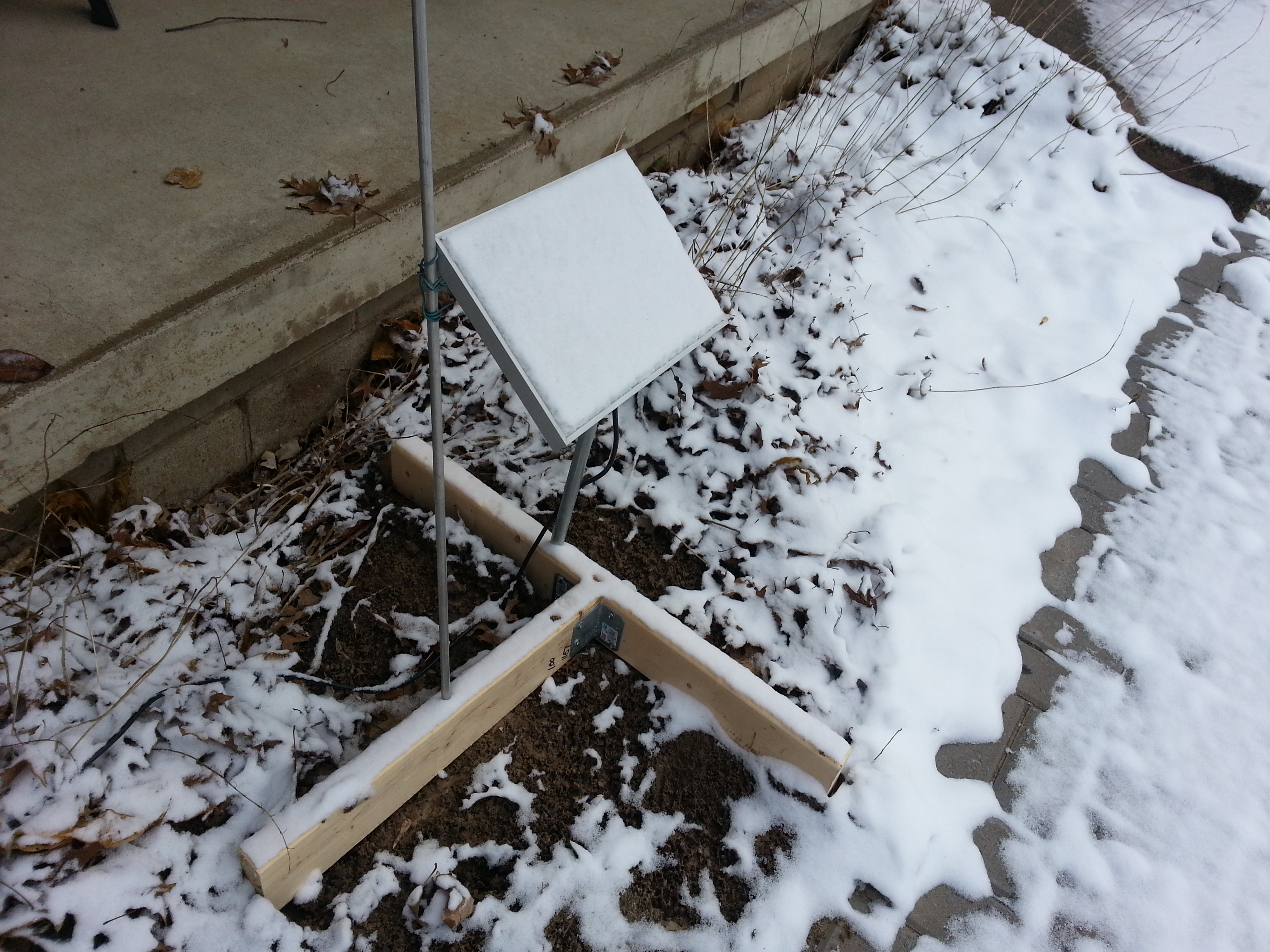
Further to the challenge of snow in northern lattitudes, snowfall becomes a variable along with solar panel angle and temperature. Essentially if the solar panel angle is not sufficiently high, the solar panel can become covered with snow which will not fall off, causing light to be blocked and therefore no power to be absorbed.
The design of the system is a mix between solar panel angle, anticipated snowfall and anticipated isolation. However, it is of note that an improved algorithm would help out in any case - even hypothetically at extremely high northern latitudes, assuming that there is at least some solar isolation during the winter months.
Our hypothesis is that the most commonly available solar systems for the hobbyist & DIY (e.g. online sales) market are systems designed around 12V applications. An additional hypothesis comes from Battery University, which stipulates as a gross generalization, that Lead Acid batteries typically provide the most economical battery solution for fixed-location systems where weight is not a concern. That being said, when designing a system for a particular application, it is important to understand the various tradeoffs which occur for a given battery system, including but not limited to:
- Deep Charging Capability
- Battery Memory
- Robustness
- Weight
- Discharge & Storage Effects (e.g. can the battery be stored in a discharged state)
- Number of charge cycles needed
- Thermal Effects
- Environmental, Disposal & Recycling Considerations
- Transport Regulations
- Cost
12V solar panels are available for purchase online which have a Voc(max) rating of 24V.
It is important to realize that this higher voltage from the solar panel can lead to an overvoltage being fed into the Arduino Yun input USB port, leading to the board being damaged. Using an off-the-shelf voltage converter going from 12V input to 5V USB output is potentially dangerous, as the 5V USB output could potentially be pulled higher than the rated input value.
To understand more about the Arduino Yun board, you can see the documentation here, which stipulates the following:
It is recommended to power the board via the micro-USB connection with 5VDC. If you are powering the board though the Vin pin, you must supply a regulated 5VDC. There is no on-board voltage regulator for higher voltages, which will damage the board.
That being said, the documentation for the ATmega32u4 microcontroller stipulates on page 383 what the absolute maximum ratings are, which are as follows:
MaximumOperatingVoltage ................ 6.0V
DC Current VCC and GND Pins ............ 200.0mA
Voltage on any Pin except RESET and VBUS with respect to Ground(8)
......................................... -0.5V to VCC+0.5V
DC Current per I/O Pin ................. 40.0mA
and further that:
Stresses beyond those listed under “Absolute Maximum Ratings” may cause permanent dam- age to the device. This is a stress rating only and functional operation of the device at these or other conditions beyond those indicated in the operational sections of this specification is not implied. Exposure to absolute maximum rat- ing conditions for extended periods may affect device reliability.
Therefore, going at or beyond 6V or at/beyond 200mA at the USB input to the Yun will damage the ATmega32u4, which will lead to the entire Yun being useless, as re-soldering a new ATmega32u4 would be a difficult process, taking time that may be beyond what is worth doing so over buying a new board.
Therefore, it is recommended to test a given power supply for its switching frequency effects when transitioning across voltages. Non-isolated point-of-load power converters work using switching effects, which cause the current to jump and spike at certain points during its cycle - at higher load draws this current spikes up higher for longer periods of time, potentially damaging the Yun, which as shown above has a maximum power input current of 200mA via the USB port.
Just as with everything going from a "higher power," electric source to an electronic source, make sure to keep in mind a couple troubleshooting notes which may save you time and hassle:
- Make sure all of the DC electronics grounds and DC electric grounds are tied together.
- Make sure all of the connections are tight / strong. This should go without saying, but if you don't, you may be sitting there wondering why WiFi won't connect or why the system won't work, only to find after several hours of troubleshooting that, "your computer wasn't plugged in," in the sense that there wasn't a strong enough connection at the actual battery, and therefore there was not enough power in one of your leads. Be careful to make sure everything is well-connected and you don't have open-circuits, or un-necessary resistive effects.
http://downloads.arduino.cc/openwrtyun/1/packages/index.html
http://www.lucadentella.it/en/2014/11/08/yun-adattatore-wifi-usb/
http://www.skillbank.co.uk/arduino/measure.htm
https://www.parallax.com/sites/default/files/downloads/601-00526-PB137-Datasheet.pdf
https://forum.arduino.cc/index.php?topic=188690.0
http://wiki.linino.org/doku.php?id=wiki:lininowebcamstream
Background:
http://hivetool.org/counter/index.html
There are some system and instrumentation-level configurations which will reduce the resolution and precision of the solar-battery measurements, which are hardware in nature. They are as follows:
- The measurements of the voltage are only accurate within +5%/-10% due to the nature of how the Arduino's internal voltage works. In essence, the Arduino assumes 5V, but really it's 4.8V. This can be improved to more the +/-2% range using a 4040 diode and some special code, as mentioned above in "Improving the On-Site Arduino Voltage Accuracy."
- There power converters introduced into the system to convert from 12V down to 9V to feed into the Arduino supply, this power converter will have an inefficiency, so while in the past a typical Arduino Yun may have a 0.25W consumption, we could assume a 0.3W power consumption to be safe. Measurement could be made on this in the future to improve accuracy.
- The linear learning model shown in Matlab on this project is sloppy and hacked together. It basically assumed that the end of the day was always 6PM, and the begining of the day was always 8AM, which of course is not the case. We could build an adjustable date model program, which would perform a lot better.
In the context of a one-day makeathon, it is important to control the scope of what is to be done to the most interesting group aspect of what needs to be done (e.g. that which has the highest potential for group conversation and random walk discovery), and try to constrain the work such that it can be accomplished during one day. Although a typical makeathon or hackathon is 8-12 hours, there is often a lot of socializing, people asking questions, and people getting antsy, wanting to go outside or whatever to take a break since it is after all, the weekend or off-time. The human mind is just not that productive sometimes. 😁 So for the purposes of the makeathon, the above problems could be abstracted away with some base assumptions.
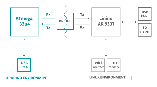
As discussed above, the Arduino Yun can be thought of as a bifurcated system, and the power consumption comes from the processor, which is like the tiniest little micro router, and a microprocessor, which is more like a dumb little chip that follows firmware instructions, as what we may have in our cars or refrigerators.
The processor is the main power consumer, probably taking about 90% of the power or more. The microprocessor is hardly a blip on the radar. However, the processor is what we use to communicate with the device, it runs the WiFi, and it runs an operating system, called OpenWRT. So essentially what we will be doing is installing some kind of server program on that OpenWRT operating system, and the server will have a REST API, such that we can POST/PULL messages from it, like with a website. A cloud server can be doing math, receiving messages from he OpenWRT system, and when there is an, "Alert," which is calculated, the server can POST a message that says, "OK, Shut down for T." The microprocessor will read that command, which is given to it by the processor. The microprocessor will then shut down OpenWRT, effectively making itself blind for time T. After time T, the microprocessor, which is very low-power, will go through through a certain number of counts and boot OpenWRT back up. Presumably this will be when there is more sunshine, according to what the server had calculated.
Now the disadvantage of this of course is that we lost all of the data during time T...but hopefully that will only be for 1 or 2 days worth of data at most, in the dead of winter, or under hurricane conditions or something.
Using this feature, we could also send instructions asking the Microprocessor to shut down the Processor at sundown, for time T(night), waking back up again at sunup. We could also have the system turn on for a short time during hurricane conditions to do a check to see where the battery level is at, post one or two data points, and then fall back asleep.
Now at this point you may rightfully be asking, "Why not just use a fundamentally low-power networking operating system, an RTOS running under FreeRTOS, or something like that. Good question - there are fundamental advantages to operating on a computer with a live operating system, e.g. we can run multiple programs at once, etc. It's basically the same arguments used in the late 80s, when some people were asking, "why would I need to run more than one program at once?" Ultimately, if we get good at running a system efficiently under "warning" conditions, we are moving more toward Fog Computing, computing at the edges, rather than computing in the cloud. Hypothetically we could collect tons of data from all over the world with a ton of different stations, and then pre-program units before deploying them in the field, so they can be intrinsically smart, on their own, thereby reducing the need to communicate back with the cloud. If we assume a cellular data model, that would mean there would be a lot fewer transaction costs of running distributed, solar systems, because we're not using SMS, cell data, etc.