A decoder and external display interface for certain HP/Agilent (now Keysight) instruments that have VFD:s (vacuum fluorescent display), which have a tendency to wear out and get unreadable over time.

This is an example with an 1.54 inch 128*64 pixel OLED and a 20x4 character LCD (of the cheapest and slowest kind), driven by the same microcontroller.
This is built for the 53131A 225 MHz Universal Frequency Counter/Timer.
It can likely be made to work also on the 53132A and 53181A counters, as well as the 58503B GPS Time and Frequency Reference Receiver with the display option (and perhaps also on those without the display option?). With some modification, it may also work on a 34401A Digital Multimeter which has a similar display but with different labels, possibly on the N3300A/N3301A (34/40 bit, or 5 bytes, SPI words?), and several others.
This implementation is built on an AVR based Arduino to keep it simple and cheap, but of course could be ported to other hardware as well.
Other display types can easily be added.
The microcontroller serial interface also shows the display readings, and works as a console for basic debugging.
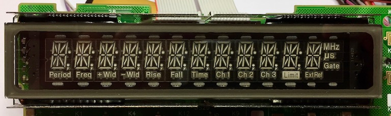
The original instrument display is a 12 character position 14 segment display, with extra segments for separators (.,:;), units, and text labels such as "Freq", "Ch1" and "Gate".
This decoder maps segment combinations to the corresponding ASCII characters codes. It also decodes the separators, the labels and the highlighting.
The interface from the instrument to the display is similar to SPI, with the main difference that the /SS line equivalent, VFDSEN, is inverted. The 53131A display uses a SN75518 VFD driver, which essentially is a 32 bit shift register with output latches and output drivers that work with the ~40 volts a VFD needs.
The SPI data is sent in 32 bit words describing which character segments, separators and labels on which character position should be lit, one word per character position. There are also 4 extra words used for highlighting of up to 4 characters, by driving those character positions and segments given on those words twice per cycle. A cycle of 12+4 words is here called a frame.
The microcontroller SPI interface needs a /SS input signal to work in slave mode. Another GPIO microcontroller pin is used to generate a fake /SS signal.
Unknown segment combinations are mapped to the character "x" - if you see any of those you can add mapping for the unknown character, see below.
Since the VFD has ./,/:/; separators between all the 12 digits, a corresponding text string has between 12 and 23 characters. In reality, it seems that there are never more than 4 separators used at the same time, except during display test, which means that the maximum length during normal use is 16 characters.
The decoder can generate full ASCII strings for all the information, but a display implementation may want to do something more fancy than just showing strings.
For more details of the protocol, see doc/protocol_descr.txt.
This implementation was tested on an Arduino Pro Micro with a ATmega32U4 and an Arduino Nano third party copy with an ATMega328. Both of those boards, and several other Arduinos, use one or the other of the SPI signals for a LED, and all signals may not be easily accessible on a pin. These problems can generally be solved by some minor modifications, but there also are boards that should work without any changes.
For more details, see doc/mcu-selection.md.
The code comes configured for the pinout of an Arduino Pro Micro.
For an Arduino Nano, in hp_display_config.h, uncomment/enable the line:
#define ARDUINO_NANO
For other controllers, you may have to adjust the pinout in the different files.
The prototype was tested with three different displays, though other kinds may be more suitable for permanent installation in the instrument.
-
An ordinary 4 rows * 20 character display with a HD44780 compatible controller, used in parallell mode (4 bits). There are many displays with good readability that are compatible with this kind, or are similar, TN/STN/VATN LCD:s, OLED:s, and even VFD:s.
-
A 0.96 inch 128*64 pixel OLED with SSD1306 controller and I2C communication.
-
A 1.54 inch 128*64 pixel OLED with SSD1309 controller and SPI communication.
Other display types can be added with a little programming.
For more details, see doc/display-selection.md.
The SPI /SS input needs to be driven by a negative active signal which the instrument does not provide, so this is done with another pin configured for output, SS_OUT.
If any of the SPI pins /SS, SCK or MOSI have a LED connected on the microcontroller board, this load must be removed, either by removing the LED itself or its current limiting resistor.
Use a ~1-3 kOhm resistor between the SPI /SS input pin and the SS_OUT pin. Resistor value is not really important, but it is safer to not just wire the pins together, and it should not be too large since together with the capacitance it will form a low pass filter and make the /SS input slow.
For wiring see:
- SPI interface to the instrument, see:
- Below
- hp_display_spi.cpp
- Interface for the parallel character display, see:
- Interface for the SPI or I2C graphical OLEDs, see:
The software can be built and downloaded to the microcontroller using the Arduino IDE.
Some general options, like choosing between a Arduino Pro Micro or Nano
for the pinout, or enabling support for the displays, can be
configured in the hp_display_config.h file.
The display drivers need interface libraries, which can be downloaded and installed from within the IDE. The LCD character display needs the "hd44780" library (version 1.0.1), and the OLED graphical displays needs the U8g2 library (version 2.24.3).
It is strongly recommended to protect the signals from the instrument, in case of an accidental short or similar.
- On the +5 volt feed, use BAT41, BAT42 or other low voltage drop diode, or at least a small fuse in the 100-200 mA range.
- On the signal wires, VFDSCLK, VFDSIN, VFDSOUT and VFDSEN, use a resistor in the range 1 kOhm to 3.3 kOhm or so.
The signals can be found on the back of the display board, where the ribbon cable connects to the board. It may be a good idea to solder some pin headers to be able to detach the cables. It then may also be good to use headers with 3 pins or more, soldered on all pins, to add some mechanical stability.
------------+                                               +-------------------
            +-----------------------------------------------+    Top of 53131A
               27                            9           1       front panel
               o  o  o  o  o  o  o     o  o  o  o  o  o  o       board, back side

         J1    o  o  o  o  o  o  o     o  o  o  o  o  o  o
               28          20 18 16    14 12 10          2
53131A J1 pins:
- 9 - GND
- 10 - +5V
- 12 - VFDSCLK - to Arduino SPI SCK
- 14 - VFDSIN - not used
- 16 - VFDSOUT - to Arduino SPI MOSI
- 18 - VFDSEN - to Arduino,
- 20 - +5V
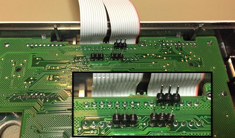
3 pin header strips soldered to the back of the instrument's display board.
You may want to check the schematics and/or find the signals using some other means. VFDSCLK has a 2 x 16 cycle ~1 MHz burst once every ~millisecond, VFDSOUT has data synchronised with VFDSCLK, VFDSEN is high during these bursts. Note that e.g. the front panel LED control signal may look very similar.
WARNING - There are 40 volts or so on some pinm and some 10 volts or so on some other pins for driving the VFD, be careful not to short pins.
Connect a terminal to the controller serial port and see if you get any readings. If not, type "debug" and get some more information that may be helpful. Some spi_frame_sync_i and spi_msgs_incom are normal, often one or a few a second, especially when using the USB port as USB has a higher priority interrupt.
There may be compatibility issues with other models and/or software revisions - it is only tested on a 53131A with software REV: 3944.
Of it will not sync on an instrument with the same VFD driver and
display, one probable cause would be that the frame sequence, the
order in which the words for the different character positions are
sent, is different. The frame sequence is used to keep track of the
when the extra highlighting fields in a frame are to arrive, and needs
to match spi_frame_seq for the decoding to work.
With some modification, the decoder may be usable on 34401A Digital Multimeter - the display is similar but has different text labels, and it seems that the display elements that are units and Gate indicators on the timing instruments are more like mode labels on the multimeter. The VFD controller may be connected differently to the VFD, in which case the SPI message and character decoding will need some work.
It may be possible to use this interface as a display on an instrument without the display option, as the 58503B. It is possible that the instrument uses VFDSIN to check that it has connectivity to the display. It may help to connect the SPI MISO signal from the microcontroller to VFDSIN. The VFD driver in the 53131A, SN75518, has a 32 bit shift register between MOSI and MISO, the AVRs only an 8 bit register, which the instrument may or may not like.
Segment combinations (characters) that have not yet been mapped to ASCII characters are displayed as "x". The firmware remembers unknown segment combinations, they can be listed with the "unk" command in the serial console. To map them, copy the hex code(s) into codes-in.list, run "python charmap.py" to try to visually decode the character and reply with either the correct character or "x" to skip. The mapping will be added to codes-mapped.list. Use "python gencode.py" to generate a C file, segmapgen.c, with the mappings, and copy that file into the Arduino project directory.
Some 14 segment display combinations are ambiguous, as the digit zero, "0", and the letter "O" as in Oscar. Some checking of the characters surrounding it will get a guess of the correct interpretation. Also, "<" and "(", and ">" and ")", look the same on the 14 segment display. They are currently mapped to "(" and ")".
Using a pure interrupt driven SPI client results in many buffer overruns on the ATMega 32U4, probably because of other interrupt service routines blocking the SPI servicing for the ~8 us window it has to read a SPI byte in 1 Mb/s. Using the SPI interrupt for the first byte and polling the remaining three bytes improves things, but also often results in buffer overrun.
Instead, the implementation uses the VFDSEN on a pin with interrupt capability, to get a high priority interrupt as early as possible in the cycle. It then polls for the four SPI bytes, locking out all other interrupts for the ~36 microseconds it takes to receive the bytes. Using this method, there are typically no buffer overruns at all.
This project is licensed under the GPL v3 license, except for a modified font that is licensed separately - see the LICENSE-font for details.