
LED Chaser circuit based on the NE555 and the CD4017 created for a San Diego workshop sponsored by Hack Club!
This circuit creates a sequential flashing animation of 10 LEDs which is operated by the CD1017 and 555 integrated circuits. It requires a VCC and GND from a 9V battery and allows you to monitor the clock output with an auxiliary pin header. The clock speed of the 555 can be altered using the trim potentiometer.


- 555 Timer IC
- CD4017 IC
- 10x LED Lights
- Resistors: 470ohm and 1K ohm
- 1uF Capacitor
- 9V Battery
- 50Kohm Trim Potentiometer
| Name | Component Name | Footprint Name |
|---|---|---|
| 555 Timer IC | NE555P | DIP-8_L9.8-W6.6-P2.54-LS7.6-BL |
| CD4017 IC | CD4017KIT | DIL16-KIT |
| LED | LED_5MM | LED-TH_BD5.0-P2.54-FD_C9900023552 |
| 1uF Capacitor | CD4017KIT | DIL16-KIT |
| 470ohm Resistor | 470Ω | RES-TH_BD3.3-L9.0-P13.00-D0.6 |
| 1K ohm Resistor | 1k | AXIAL-0.3 |
| Trim Potentiometer | 50k | RES-ADJ_3296X |
| VCC and GND Pins | Header | HEADER-FEMALE-2.54_1X2 |
| CLK Pin | C81276 | HDR-TH_1P-P2.54-V-M |
The 555 IC is configured to be in astable mode. This causes the IC to behave like an oscillator switching its output between HIGH and LOW states to generate a square wave signal which can be fed into the CD4017 IC.
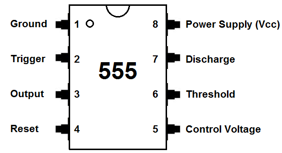
The pinout characteristics of the 555 is as follows:
| Pin Number | Name | Function |
|---|---|---|
| 1 | GND | Ground |
| 2 | TRIG | Trigger Input: Used to trigger the timer |
| 3 | OUT | Output: Provides the timer's output signal |
| 4 | RESET | Reset: Resets the timer's internal flip-flop |
| 5 | CTRL | Control Voltage: Used to control the threshold |
| 6 | THRES | Threshold Input: Sets the threshold for timing |
| 7 | DISCH | Discharge Output: Used to discharge timing capacitor |
| 8 | VCC | Supply Voltage: Typically +5V |
The internal mechanism of the 555 consists of two comparators
Belonging to the CMOS 4000 series of logic chips, the CD4017 is a decade counter with 10 decoded outputs (labeled Q0 through Q9) used to light up our 10 LEDs! It sequentially counts from 0 to 9 on its outputs for each clock pulse applied to its clock input (CLK) and then resets back to 0.
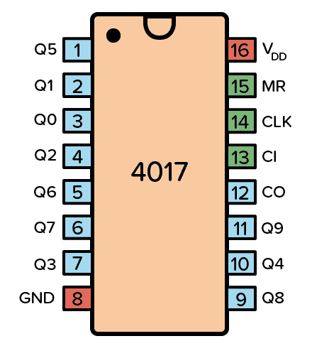
The pinout characteristics of the CD4017 is as follows:
| Pin Number | Name | Function |
|---|---|---|
| 1 | CLK | Clock Input: Accepts clock pulses to count |
| 2 | Q0 | Output 0: Output for count state 0 |
| 3 | Q1 | Output 1: Output for count state 1 |
| 4 | Q2 | Output 2: Output for count state 2 |
| 5 | Q3 | Output 3: Output for count state 3 |
| 6 | Q4 | Output 4: Output for count state 4 |
| 7 | Q5 | Output 5: Output for count state 5 |
| 8 | GND | Ground (0V): Reference voltage |
| 9 | Q6 | Output 6: Output for count state 6 |
| 10 | Q7 | Output 7: Output for count state 7 |
| 11 | Q8 | Output 8: Output for count state 8 |
| 12 | Q9 | Output 9: Output for count state 9 |
| 13 | RESET | Reset Input: Resets the counter to state 0 |
| 14 | VDD | Supply Voltage: Typically connected to +5V or +9V |
| 15 | ENABLE | Enable Input: Enables counting operation |
| 16 | CLOCK INHIBIT | Clock Inhibit: Disables clock pulse input |
If you enjoyed this design, please consider becoming a sponsor or donating on Buy Me a Coffee in order to fund my future projects.
To check out my other works, visit my GitHub profile.