
By Alexander Richter, info@theartoftinkering.com 2022
please consider supporting me on Patreon:
https://www.patreon.com/theartoftinkering
Website: https://theartoftinkering.com
Youtube: https://youtube.com/@theartoftinkering
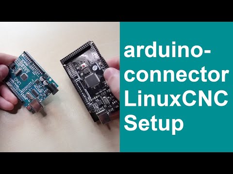
This Project enables you to connect an Arduino to LinuxCNC and provides as many IO's as you could ever wish for. This Software is used as IO Expansion for LinuxCNC.
It is NOT intended for timing and security relevant IO's. Don't use it for Emergency Stops or Endstop switches!
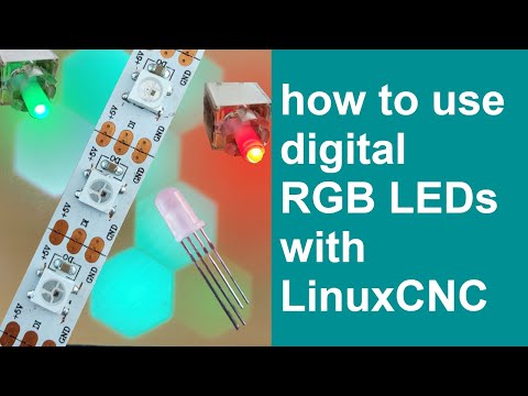
You can create as many digital & analog Inputs, Outputs and PWM Outputs as your Arduino can handle. It also supports Digital LEDs such as WS2812 or PL9823. This way you can have as many LEDs as you want and you can also define the color of them with just one Pin.
| Currently the Software Supports: | Arduino Mega | Ardunio Micro | Ardunio Uno |
|---|---|---|---|
| Analog Inputs | Up to 16 | Up to 12 | Up to 6 |
| Digital Inputs | Up to 52 | Up to 20 | Up to 12 |
| Digital Outputs | Up to 52 | Up to 20 | Up to 12 |
| PWM Outputs | Up to 15 | Up to 7 | Up to 6 |
| Digital RGB LEDs like WS2812 or PL9823 | ~ 1000 | ~ 1000 | ~ 1000 |
| latching Potentiometers / Selector Switches | Up to 16 | Up to 12 | Up to 6 |
| binary encoded Selector Switch | 1 | 1 | 1 |
| Quadrature Encoder Input | 3 or more | 1 or more | 1 or more |
| Joystick Support (2Axis) | 8 | 6 | 3 |
| Matrix Keyboard | 1 | 1 | 1 |
| Multiplexed LEDs | ~ 1000 | ~ 1000 | ~ 1000 |
Planned Features:
- Temperature Probes using 4.7k Pullup-Resistor
- Support for i2C LCDs
This software works with LinuxCNC 2.8, 2.9 and 2.10. For 2.8, however, you have to change #!/usr/bin/python3.9 in the first line of arduino.py to #!/usr/bin/python2.7.
You should be able to use any Arduino or Arduino compatible Boards, currently Tested are: Arduino Mega 2560 Arduino Nano Arduino Duemilanove
Other Arduino compatible Boards like Teensy should work fine also.
To Install LinuxCNC_ArduinoConnector.ino on your Arduino first work through the settings in the beginning of the file. The Settings are commented in the file.
To test your Arduino you can connect to it after flashing with the Arduino IDE. Set your Baudrate to 115200.
In the beginning the Arduino will Spam E0:0 to the console. This is used to establish connection.
Just return E0:0 to it. You can now communicate with the Arduino. Further info is in the Chapter Serial Communication
-
configure the .ino file to your demands and flash it to your arduino
-
connect the arduino to your LinuxCNC Computer via USB
-
install python-serial
sudo apt-get install python-serial -
edit arduino.py to match your arduino settings. If you're running 2.8 change
#!/usr/bin/env python3 in the first line of arduino.py to #!/usr/bin/python2.7. -
also check if the Serial adress is correct for your Arduino. I found it easyest to run
sudo dmesg | grep ttyin Terminal while plugging and unplugging the arduino a couple of times and whatch which entry is changing. -
make arduino.py executable with chmod +x, delete the suffix .py and copy it to /usr/bin
sudo chmod +x arduino.py
sudo cp arduino-connector.py /usr/bin/arduino-connector -
add this entry to the end of your hal file:
loadusr arduino-connector
To test your Setup, you can run halrun in Terminal.
Then you will see halcmd:
Enter loadusr arduino-connector and then show pin
All the Arduino generated Pins should now be listed and the State they are in. You can click buttons now and if you run show pin again the state should've changed.
you can also set Pins that are listed in DIR as IN. Enter "setp arduino.DLED.1 TRUE" for example. This will set said Pin to HIGH or in this case, if you have it set up turn the 2. Digital LED on.
You can now use arduino pins in your hal file. Pin Names are named arduino.[Pin Type]-[Pin Number]. Example: arduino.digital-in-32 for Pin 32 on an Arduino Mega2560
Watch the Video explanation on Youtube:
In the Arduino .ino File you will see the configuration Parameters for each kind of Signal. For example we will take a look at the First setting:
#define INPUTS //Use Arduino IO's as Inputs. Define how many Inputs you want in total and then which Pins you want to be Inputs.
#ifdef INPUTS
const int Inputs = 5; //number of inputs using internal Pullup resistor. (short to ground to trigger)
int InPinmap[] = {37,38,39,40,41};
#endif
You can easily modify it to fit your needs. Set Inputs to how many Pins you want to use as Inputs and edit the Array InPinmap by setting the Pin Number that should be set as Input. You can add as many as you want until your Arduino runs out of available Pins.
After you've set your Pin definitions, copy your settings over to the arduino.py file. The .ino is written in C while the other one is written in Python, hence the Syntax is a little different. You only need to worry that the contents of the variables match.
Inputs = 5
InPinmap = [37,38,39,40,41]
These are used for example to connect Potentiometers. You can add as many as your Arduino has Analog Pins. The Software has a smoothing parameter, which will remove jitter.
Digital Inputs use internal Pullup Resistors. So to trigger them you just short the Pin to Ground. There are two Digital Input Types implemented. Don't use them for Timing or Safety relevant Stuff like Endstops or Emergency Switches.
- INPUTS uses the spezified Pins as Inputs. The Value is parsed to LinuxCNC dirketly. There is also a inverted Parameter per Pin.
- Trigger INPUTS (SINPUTS) are handled like INPUTS, but simulate Latching Buttons. So when you press once, the Pin goes HIGH and stays HIGH, until you press the Button again.
Digital Outputs drive the spezified Arduinos IO's as Output Pins. You can use it however you want, but don't use it for Timing or Safety relevant Stuff like Stepper Motors.
Digital LED's do skale very easily, you only need one Pin to drive an infinite amount of them. To make implementation in LinuxCNC easy you can set predefined LED RGB colors. You can set a color for "on" and "off" State for each LED. LED colors are set with values 0-255 for Red, Green and Blue. 0 beeing off and 255 beeing full on. Here are two examples:
-
This LED should be glowing Red when "on" and just turn off when "off". The Setting in Arduino is:
int DledOnColors[DLEDcount][3] = {{255,0,0}};int DledOffColors[DLEDcount][3] = {{0,0,0}}; -
This LED should glow Green when "on" and Red when "off".
int DledOnColors[DLEDcount][3] = {{0,255,0}};int DledOffColors[DLEDcount][3] = {{255,0,0}};
Depending on the used LED Chipset, Color sequence can vary. Please try, which value correspons to which color with your LED's. Typically it should be R G B for WS2812 and G R B for PL9823. You can mix both in one chain, just modify the color values accordingly.
Watch the Video explanation on Youtube:
This is a special Feature for rotary Selector Switches. Instead of loosing one Pin per Selection you can turn your Switch in a Potentiometer by soldering 10K resistors between the Pins and connecting the Selector Pin to an Analog Input. The Software will divide the Measured Value and create Hal Pins from it. This way you can have Selector Switches with many positions while only needing one Pin for it.
Some rotary Selector Switches work with Binary Encoded Positions. The Software Supports Encoders with 32 Positions. (this could be more if requested) For each Bit one Pin is needed. So for all 32 Positions 5 Pins are needed = 1,2,4,8,16 If this feature is enabled, 32 Hal Pins will be created in LinuxCNC.
The Arduino only works, if LinuxCNC is running and an USB Connection is established. To give optical Feedback of the State of the connection a Status LED setting is provided. This can be either an LED connected to an Output Pin or you can select one LED in your Digital LED Chain.
- It will flash slowly after startup, when it waits for communication setup by LinuxCNC.
- It will glow constantly when everything works.
- it Will flash short when Connection was lost.
Connecting Matrix Keyboards is supported. You can adapt the Settings to fit all kinds of Matrix Keyboards. The Software can emulate an Keyboard in Linux. This is useful, because for some Keys you may want to enter Letters or Numbers, for others you may want to set functions in LinuxCNC. To input Text it is neccessary to emulate Keypresses. In the Config file you can define, which Key should be connected to LinuxCNC as Inputpins and which should be handled like a Keyboard in Linux.
To run Matrix Keyboards requires you to install and test "xdotool". You can install it by typing "sudo apt install xdotool" in your console. After installing "xdotool type "Hello World" should return "Hello World" in the Terminal. If it doesn't, something is not working and this program will not work either. Please get xdotool working first.
In the Settings a cheap 4x4 Keyboard is used such as https://theartoftinkering.com/recommends/matrix-keyboard/ (referral link)
WaWatch the Video explanation on Youtube:
ch the Video explanation on Youtube:

Special mode for Multiplexed LEDs. This mode is experimental and implemented to support Matrix Keyboards with integrated Key LEDs. Please provide feedback if u use this feature. check out this thread on LinuxCNC Forum for context. https://forum.linuxcnc.org/show-your-stuff/49606-matrix-keyboard-controlling-linuxcnc for Each LED an Output Pin is generated in LinuxCNC.
If your Keyboard shares pins with the LEDs, you have to check polarity. The Matrix Keyboard uses Pins as such:
rowPins[numRows] = {} are Pullup Inputs colPins[numCols] = {} are GND Pins
the matrix keyboard described in the thread shares GND Pins between LEDs and KEYs, therefore LedGndPins[] and colPins[numCols] = {} use same Pins, LedVccPins[] are Outputs and drive the LEDs.
Quadrature Encoders require a Library to be installed. More Info about the used Library can be found here: https://www.pjrc.com/teensy/td_libs_Encoder.html It can be downloaded here: https://www.arduino.cc/reference/en/libraries/encoder/
This function is made with Rotating encoders in mind but supports all kinds of quadrature Signals. For easy implementation in LinuxCNC two modes are supported.
1 = Up or Down Signals per Impuls , this is intended for use with Feed or Spindle Speed Override. 2 = Counter Signal, this is intended for the usecase of using the Encoder as MPG for example. Arduino will count Impulses and add them to a counter, which then is send to LinuxCNC. there you can connect it to x & y yog signals.
If your Encoder can be pressed and there is a button inside, use the Input or Latching Input functionality mentioned above.
Encoders have 2 signals, which must be connected to 2 pins. There are three options.
Best Performance: Both signals connect to interrupt pins.
Good Performance: First signal connects to an interrupt pin, second to a non-interrupt pin.
Low Performance: Both signals connect to non-interrupt pins, details below.
| Board | Interrupt Pins | LED Pin(do not use) |
|---|---|---|
| Teensy 4.0 - 4.1 | All Digital Pins | 13 |
| Teensy 3.0 - 3.6 | All Digital Pins | 13 |
| Teensy LC | 2 - 12, 14, 15, 20 - 23 | 13 |
| Teensy 2.0 | 5, 6, 7, 8 | 11 |
| Teensy 1.0 | 0, 1, 2, 3, 4, 6, 7, 16 | |
| Teensy++ 2.0 | 0, 1, 2, 3, 18, 19, 36, 37 | 6 |
| Teensy++ 1.0 | 0, 1, 2, 3, 18, 19, 36, 37 | |
| Arduino Due | All Digital Pins | 13 |
| Arduino Uno | 2, 3 | 13 |
| Arduino Leonardo | 0, 1, 2, 3 | 13 |
| Arduino Mega | 2, 3, 18, 19, 20, 21 | 13 |
| Sanguino | 2, 10, 11 | 0 |
Watch the Video explanation on Youtube:

Joysticks use a similar implementation as Quadrature encoders and are implemented with the usecase as MPG in mind. Connect your X and Y Pin of your Joystick to an Analog Pin of your choice. Depending of the position of the Joystick it will add or substract from a counter, which then is send to LinuxCNC. The more you move the Joystick from the middle Position to the end of movement the more will be added to the counter, which will increase the speed of motion in Jog mode.
Currently Joysticks will only generate an counter in LinuxCNC.
Watch the Video explanation on Youtube:
The Send and receive Protocol is : After Bootup the Arduino will continuously print E0:0 to Serial. Once the Host Python skript runs and connects, it will answer and hence the Arduino knows, the connection is established.
For testing you can still connect to it with your Serial terminal. Send E0:0, afterwards it will listen to your commands and post Input Changes.
Data is always only send once, everytime it changes.
| Signal | Header | direction | Values |
|---|---|---|---|
| Inputs & Toggle Inputs | I | write only | 0,1 |
| Outputs | O | read only | 0,1 |
| PWM Outputs | P | read only | 0-255 |
| Digital LED Outputs | D | read only | 0,1 |
| Analog Inputs | A | write only | 0-1024 |
| Latching Potentiometers | L | write only | 0-max Position |
| binary encoded Selector | K | write only | 0-32 |
| Matrix Keyboard | M | write only | 0,1 |
| Quadrature Encoders | R | write only | 0,1,counter |
| Joystick | R | write only | counter |
| Connection established | E | read/ write | 0:0 |
Example: You want to Tell LinuxCNC you pressed Input on GPIO Pin 2, The command would be : "I2:1". If LinuxCNC sends the Arduino to Set GPIO Pin 3 HIGH, the command would be: "O3:1" and "O3:0" to set it LOW.
Command 'E0:0' is used for connectivity checks and is send every 5 seconds as keep alive signal. If it is not received in Time, the connection is lost and the arduino begins flashing an LED to alarm the User. It will however work the same and try to send it's Data to the Host.
This program is free software; you can redistribute it and/or modify it under the terms of the GNU General Public License as published by the Free Software Foundation; either version 2 of the License, or (at your option) any later version. This program is distributed in the hope that it will be useful, but WITHOUT ANY WARRANTY; without even the implied warranty of MERCHANTABILITY or FITNESS FOR A PARTICULAR PURPOSE. See the GNU General Public License for more details. You should have received a copy of the GNU General Public License along with this program; if not, write to the Free Software Foundation, Inc., 59 Temple Place, Suite 330, Boston, MA 02111-1307 USA