Important: This project based on my ioBroker IoT Framework V5
AndreasExner/ioBroker-IoT-Framework: ioBroker IoT Framework (based on NodeMCU ESP8266) (github.com)
Please refer to this documentation for the the basic setup and configuration.
Required Version: 5.3.2 (or higher)
This sketch needs the hardware serial interface for the communication with the wind direction sensor (RS485). That requires to change the serial output for debug and runtime information (Serial.print) to serial1. The attached version of the framework includes the changes already.
This sketch reads the wind speed and direction from devices similar to these (no affiliate links!):
Both are sold from different sellers and under different names as well. Since the wind speed sensor offers an analog output the wind direction sensor uses the RS486 interface.
The raw data will be send to the ioborker, because de nosing can be a challenging part of the this project.
For the wind speed and direction, the value is measured with round about 1 Hz and written into an array. The array is submitted to iobroker on every interval. The maximum size of the array is limited by the maximum length of an URL (2000 characters) to 250. The recommended interval for a "real time" display should be between 30 and 60. On the iobroker side, the array must be processed do extract the required information (see processWindSensorData.js for details).
Important: the target datapoints are not part of the json files!
Often the remote device is mounted somewhere on a rooftop or another inconvenient place. That's where this tool comes in and offers you a simulation for your lab:
Both sensors require 12-24V DC power. The RS485 shield is used to convert RS485 into TTL. The FT232 is used for serial1 (debug/info)
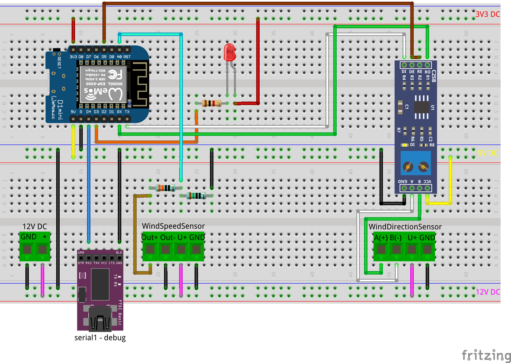
Voltage divider resistors: 330 ohm and 150 ohm, 1% or better, 1/4 watts
It took me a lot of time to fiddle out all the challenges within the RS232/RS485 communication. Some findings are:
- Ground your STP cable shield on one end
- The conversation form RS232 to RS485 requires a good timing
- Pulling up the RE/DE pulls up RX of the ESP as well. This leads into zero frames / framing errors between the frames
- -> CRC check / trimming of zero frames is required
- -> The RX frame size must be known / defined
Version: F5_1.1 2020-12-14
- Major bugfix: sketch does not work with debug=false
- Major improvements and bugfixes for the UART communication: CRC check, remove zero bytes etc.
- changed wind speed data transfer (for de-noising)
- minor fixes and improvements
Version: F5_1.0 (release) 2020-12-06
- Software
- Arduino IDE 1.8.13 (Windows)
- EspSoftwareSerial 6.10.0 plerup/espsoftwareserial: Implementation of the Arduino software serial for ESP8266 (github.com)
- Hardware
- NodeMCU Lolin V3 (ESP8266MOD 12-F)
- NodeMCU D1 Mini (ESP8266MOD 12-F)
- 5 V MAX485 / RS485 Modul TTL to RS-485 MCU
- You need a running Arduino IDE and at least basic knowledge how it works.
- You also need a running ioBroker instance and a little more than basic knowledge on that stuff.
- You need a REST API in your ioBroker setup
- You need to secure the REST API (for example, expose the required data only and hide any confidential and secret stuff)
- You need a userdata section in your ioBroker objects
- You should know how to work with IoT devices and electronics
- You need to read this first: AndreasExner/ioBroker-IoT-Framework: ioBroker IoT Framework (based on NodeMCU ESP8266) (github.com)
- Create a folder in your Arduino library folder
- Copy the primary sketch (e.g. WindSensor.ino) and the extension file (AEX_iobroker_IoT_Framework.ino) into the folder
- Open the primary sketch (e.g. WindSensor.ino)
- Install required libraries into your Arduino IDE
- Create (import) the datapoints in iobroker
- 0_userdata.0.IoT-Devices.07.json (generic device configuration and monitoring)
- 0_userdata.0.IoT.WindSensor.json (specific device configuration and data, production)
- 0_userdata.0.IoT-Dev.WindSensor.json (specific device configuration and data, development, optional)
- Set values for datapoints (see iobroker datapoints)
// device settings - change settings to match your requirements

const char* ssid     = "<ssid>"; // Wifi SSID
const char* password = "<password>"; //Wifi password

String SensorID = "DEV"; //predefinded sensor ID, DEV by default to prevent overwriting productive data

int interval = 10;  // waiting time for the first masurement and fallback on error reading interval from iobroker

bool DevMode = true; //enable DEV mode on boot (do not change)
bool debug = true; //debug to serial monitor
bool led = true; //enable external status LED on boot
bool sensor_active = false; // dectivate sensor(s) on boot (do not change)- Enter proper Wifi information
- The
SensorIDis part of the URL's and important for the the iobroker communications Intervaldefines the delay between two data transmissions / measurements. This value is used initially after boot. The interval dynamically updates from iobroker- The
DevModeswitch prevents the device from sending data into your productive datapoints. It is enabled by default and can be overwritten dynamically from iobroker debugenables a more detailed serial outputledenables the onboard led (status)- The
sensor_activeswitch disables the loading of hardware specific code on startup. This is very useful to test a sketch on the bread board without the connected hardware. It is disabled by default and gets dynamically enabled from the iobrocker during boot, as long as nothing else is configured.
/*
 * build base URL's
 * Change IP/FQND and path to match your environment
 */

String baseURL_DEVICE_GET = "http://192.168.1.240:8087/getPlainValue/0_userdata.0.IoT-Devices." + SensorID + ".";
String baseURL_DEVICE_SET = "http://192.168.1.240:8087/set/0_userdata.0.IoT-Devices." + SensorID + ".";
The base url's, one for read and one to write data, are pointing to your iobroker datapoints in the devices section. The SensorID will be added to complete the path.
The default path for the devices root folder is: 0_userdata.0.IoT-Devices. When the path is changed, it has to be changed in the sketch as well.
It is mandatory to setup the following datapoints prior the first device boot:
-
DevModeIf true, the baseURL's for the IoT-Dev section are used to prevent overwriting your production data. Also see generic device section. -
LEDControls the status LED. Also see generic device section. -
SensorActiveControls the hardware sensors. Also see generic device section. -
SensorNameEasy to understand name for the sensor. Not used in the code. -
baseURL_GET_DEVpoints to the IoT-Dev datapoints in iobroker (e.g. 0_userdata.0.IoT-Dev.DEV)-
http://192.168.1.240:8087/getPlainValue/0_userdata.0.IoT-Dev.WindSensor.
-
-
baseURL_SET_DEVpoints to the IoT-Dev datapoints in iobroker (e.g. 0_userdata.0.IoT-Dev.DEV)-
http://192.168.1.240:8087/set/0_userdata.0.IoT-Dev.WindSensor.
-
-
baseURL_GET_PRODpoints to the IoT datapoints in iobroker (e.g. 0_userdata.0.IoT.Weather)-
http://192.168.1.240:8087/getPlainValue/0_userdata.0.IoT.WindSensor.
-
-
baseURL_SET_PRODpoints to the IoT datapoints in iobroker (e.g. 0_userdata.0.IoT.Weather)-
http://192.168.1.240:8087/set/0_userdata.0.IoT.WindSensor.
-
These datapoints are for output only:
-
ErrorLogLast info/error message from the device -
MACHW wifi mac address of the device -
RSSILast wifi RSSI information from the device -
ResetDepricated
Depending on the DevMode, the device reads config and writes data into different datapoint sections:
- Development root folder:
0_userdata.0.IoT-Dev - Production root folder:
0_userdata.0.IoT
It is recommended to keep the datapoints in both sections identical to avoid errors when changing the DevMode. The values can be different. Setup these datapoints before boot up the device:
Interval[10] Defines the delay (in seconds) between two data transmissionsA0_Step_VoltageThe voltage per step of the A/D converter for the windspeed sensor. Due to the line resistance it might be necessary to adjust these values individually. A good point to start is 0.03 V.
These datapoints are for output only:
WindDirectionArrayArray of wind direction valuesWindSpeedArrayArray of wind speed valuesSensorIDSensor device IDcrcErrorsCRC errors during the last intervalrxTimeOutsRX timeouts (missed frames) during the last interval
void build_urls() {

  URL_SID = baseURL_DATA_SET + "SensorID?value=" + SensorID;
  URL_INT = baseURL_DATA_GET + "Interval";

  URL_A0_Step_Voltage = baseURL_DATA_GET + "A0_Step_Voltage";
  URL_crcErrors = baseURL_DATA_SET + "crcErrors?value=";
  URL_rxTimeOuts = baseURL_DATA_SET + "rxTimeOuts?value=";
  URL_WindDirectionArray = baseURL_DATA_SET + "WindDirectionArray?value=";
  URL_WindSpeedArray = baseURL_DATA_SET + "WindSpeedArray?value=";
}
These url's are pointing to the iobroker datapoints, defined in the json files and can be changed if required.
- Connect Wifi
- Get Wifi State
- Get the dynamic configuration from iobroker (generic devices section)
- Build specific device URL's (based on the dynamic configuration)
- Send devices IP address
- Send device ID
- Send information about the last restart / reset
- Run's setup for active sensors
Every n-th tick, defined by the Interval, the following sequence will proceed:
- Loop (1 Hz)
- Get data of all sensors
- Serial output all sensor data
- Interval reached
- Get Wifi State (try reconnect first, then reset if not connected)
- Send devices IP address
- Get the dynamic configuration from iobroker (generic devices section)
- Build specific device URL's (based on the dynamic configuration)
- Send data to iobroker
- Get configuration data (A0_Step_Voltage) for wind sensor from iobroker
- Run setup for inactive sensors (if activated now)
- Get the new interval (specific device section)
- LED Blink