Download release here.
This library presents solutions in the fields of prototyping and computer vision, that have been developed instead of the corresponding existing standard ones.
Please send us any of your requests, recommendations and complaints to feedback@arcona.io.
-
PACKAGE CONTENTS The package consists of the following files:
-
EULA.txt – the end user license agreement (EULA);
-
Manual.doc (this one);
-
ArconaCore_111.h – the header library file.
-
ArconaCore_111.lib, ArconaCore_111d.lib - the compiled library files in the release and debug configuration respectively.
-
ArconaCoreTest.cpp – an example of using of the library.
-
TECHNICAL INFORMATION The ArconaCore is a statically–linked C++ library that is intended to use in Microsoft Visual C++ © environment of version 2013 or higher. The library is assembled with all necessary dependencies, so no extra procedures are needed to begin use it. The current version works on 64x platforms only. The hardware system requirements depend on the dimension and complexity of a specified input data, but for a majority of cases a platform with Intel I5 CPU and 4 GB of memory is sufficient.
-
OVERVIEW During our work on the Arcona project (www.arcona.io) we met several problems that could not be satisfactory solved by using of existing algorithmic and software solutions. It is caused by that we need to deal with quite noise and incomplete input data to generate our AR navigation markers remotely. Because such problems are actual not only for AR developers we have started this public Arcona Core library project that contains our own solutions for AR/VR and related fields such as prototyping, surface reconstruction, image processing and so on.
Of course, the presented solutions aren’t the best for any purpose, but in several particular important cases they work better than the corresponding ones proposed by such famous software products like PCloud, OpenCV, 3D SYSTEMS® and others. Advantage of the presented methods is provided by using elements of neural network technologies, as a particular, multi-layer convolutional networks. So, the presented solutions aren’t wrappers of the existing standard methods, although the OpenCV library tools are used for loading and beginning blurring of input images. On the base of feedbacks after releasing of version 1.00 interface of this version is simplified. As a particular, now it contains only hi-level universal methods with minimized number of parameters. The set of intermediate data types is minimized as well. The library contains 3 sections described in the subsequent paragraphs. -
GENERAL PURPOSE SECTION This section contains the following auxiliary data types and functions: Enumeration RESULT defines the type of result returned by operational functions. Function get_done_percentage returns the progress index of a currently working operational function (note, that only functions with a possible long duration of work support the progress index obtaining). A simple example of this function’s usage is adduced in “example.cpp”.
-
PROTOTYPING SECTION
5.1 Input/Output Data Types VECTOR – represents a point (vector) in 3D. TRIANGLE – represents a triangle of a 3D mesh, each triangle vertex is defined by its index in the corresponding mesh point array. MESH - represents a set of points or a triangle mesh: • Points addresses the point array; • NumPoints defines the point array size; • Normals addresses the array of normal vectors at the corresponding points of array Points; thus, its size should be equal to NumPoints as well or, if the point normals aren't specified, Normals should be initialized by NULL; • Triangles addresses the triangle array; • NumTriangles defines the triangle array size; in the case of a point cloud Triangles should be set to NULL and NumTriangles is equal to 0; • allocate(unsigned num_points, bool normals, unsigned num_triangless) allocates the object’s arrays and sets the corresponding size members; the point array is created with the size equal to num_points; if the parameter normal is “true” the array of normals is allocated with the same size as well; the array of triangles is allocated with the size equal to num_triangles; • release() returns the object to the non-allocated state.
5.2 Operational Functions The function make_repair_mesh produces a triangle mesh model from a specified input and has the following parameters: • in_mesh can contain only a trivial point cloud (Normals == NULL, Triangles == NULL , NumTriangles == 0), a cloud of points with normals (Triangles == NULL , NumTriangles == 0) or a mesh (all the fields should be valid); note, that if the input contains at least one triangle it is interpreted as a mesh to repair and the beginning mesh generation step is skipped; otherwise the input is considered as a point cloud and the corresponding most suitable mesh generation method is applied first; • flags specifies extra input data properties and processing modes by combination of the following flags (defined by the enumeration MESH_REPAIRING_FLAGS): BasRelief specifies that the input is an unclosed bas-relief (an example is in figure F5.2.1); ignoring this mode for such samples essentially increases the processing time and leads to improper results, because by default the function tries to make a manifold; TunnelLikeHolesExpected specifies that the input can contain tunnel-like holes whose internal parts are lost (an example is in figure F5.2.2); detecting such holes decreases the performance and is recommended only if such holes really can take place; NoSelfIntersections specifies that the repairing should be performed in a mode that prevents possible self-intersections in the output model; the processing duration in this case can be sufficiently longer; at the same time, processing without this option allows to obtain the output without self-intersections in a majority of cases; • out_mesh is the resulting data container; in the case of success it always contains a triangle mesh with the defined normals at its points; it should not be allocated before, its allocation is made inside the function. This function supports the progress indication. Because exact prediction of the required amount of work can’t be made with a reasonable cost, during the repairing the progress index can roll-back to a previous position several times. The function make_repair_stl is a variant of the previous method that repairs stl mesh files.

Figure F5.2.1
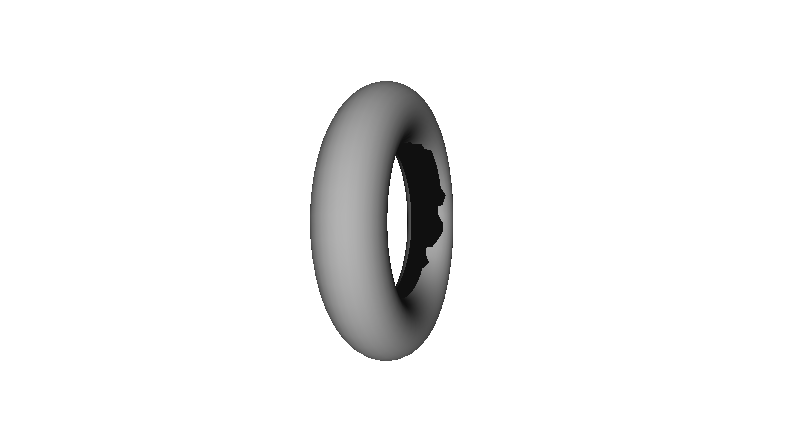
Figure F5.2.2
- COMPUTER VISION SECTION 6.1 Output Data Types POINT represents an image point. FPOINT represents a 2D point (vector) with floating point coordinates. SEGMENT defines a line segment in the image plane: • Origin specifies the segment origin point; • Direction specifies the segment directional unit vector; • Length specifies the segment length; • LineId specifies the non-zero Id of the line that contains this segment. SEGMENTS describes a segment array: • Segments points to the array data; segments of the same line are placed one by one from the first segment to the last one; • NumSegments specifies the total number of segments; • release() returns the object to the non-allocated state.
CORNER describes a corner in the image plane:
• Apex specifies the corner apex;
• Direction is the unit vector that is opposite to the bisectrix ray;
• Angle is the value of the corner aperture angle.
CORNERS describes a corner array:
• Corners addresses the array data;
• NumCorners is the number of array elements;
• release() returns the object to the non-allocated state.
CAMERA_PARAMETERS describes intrinsic parameters from camera matrix:
• f- the focal lengths expressed in pixel units;
• cx, cy - a principal point coordinates.
DISTORTION_COEFFICIENTS describes distortion parameters of the camera:
• k1, k2, k3 - radial distortion coefficients;
• p1, p2 - tangential distortion coefficients.
6.2 Operational group The function extract_geometry(const _IplImage*, …) detects lines and corners in a specified input image: • image adresses an input OpenCV image object; • context manages the detecting process by a set of the following parameters: BlurRadius defines the radius of initial image blurring to reduce influence of noise and compression artifacts; should be a positive odd value from the range [1, 15]; BrightnessNoise, ColorNoise specify the brightness and color noise levels of the input image respectively; LineLengthThreshold specified the bottom threshold value for detected line length; lines with the length less than this threshold value are ignored; StraightLineMode if this parameter is “true” only straight lines in the input image are detected; • out_segments and out_corners address output containers for detected line segments and corners respectively; these containers should not be allocated before; if lines or corners are not needed, the corresponding pointer should be set to NULL. The function extract_geometry(const wchar_t*, …) is a version of the function described above with the difference that it takes an input image directly from a specified file, so in this case any dealing with OpenCV is not needed. This function in the debug version generates “bmp” image files with the names + “_LINES” and “_CORNERS” that visualize the sets of detected lines and corners respectively. The function _IplImage* load_image(const char* filename) loads image from file to _IplImage struct. After stop working with image, you should clear the memory using the function release_image to avoid memory leaks. The function void release_image(_IplImage **image) release memory allocated for image.
6.3 Camera Calibration and Distortion Correction group The function RESULT InitCalibration(int board_width, int board_height) initialize camera calibration process. • board_width - the number of cells in the pattern chessboard horizontally; • board_height - the number of cells in the pattern chessboard vertically. The function int AddImage(_IplImage*& img, bool *chess_found = nullptr) adds image to camera calibration process. • Img – address of an input IplImage struct, that contains image. • chess_found – if the chess pattern is found on the image then *chess_found sets to true; otherwise sets to false. The function RESULT Calibrate(bool good_calibration = nullptr) run camera calibration process, should be called after all images with pattern are added with AddImage function. • good_calibration - if the calibration was successful and accurate then good_calibration sets to true; otherwise sets to false. The function RESULT CorrectDistortion(const _IplImage input, _IplImage& corrected) correct distortion in the image, if the camera parameters are available (after camera calibration or after loading parameters from file). • input – address of an input IplImage struct, that contains image for correction; • corrected – address of an output struct for corrected image. The function bool GetCalibratedStatus() shows the status of the availability of suitable camera parameters (true after successful calibration or after successful loading from file). The function RESULT LoadParams(const char *params_file_name) load camera parameters from file. The function RESULT SaveParams(const char *file_name) save camera parameters to file. The function CAMERA_PARAMETERS GetCameraMatrix() after camera parameters are calculated or loaded returns struct with camera matrix parameters. Returns struct of zeros (with active = false) in case of unsuccessful run. The function DISTORTION_COEFFICIENTS GetDistortionCoefficents() after camera parameters are calculated or loaded returns struct with camera distortion parameters. Returns struct of zeros (with active = false) in case of unsuccessful run.