Mixed signal circuit implemented as a part of the Mixed Signal SoC Design Hackathon by IIT Bombay and Google
- Abstract
- Reference Circuit Diagram
- Reference Waveform
- Circuit Explanation
- State Diagram
- Software Used
- Circuit Schematic in eSim
- Verilog Code
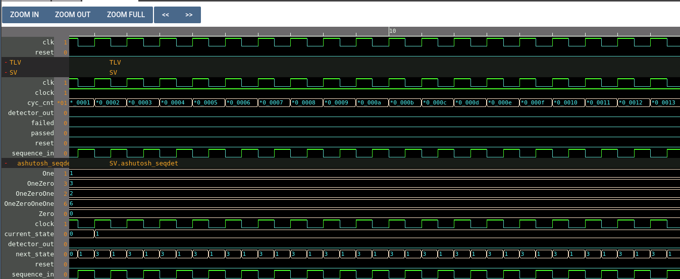
- Makerchip
- Makerchip Plot
- Netlists
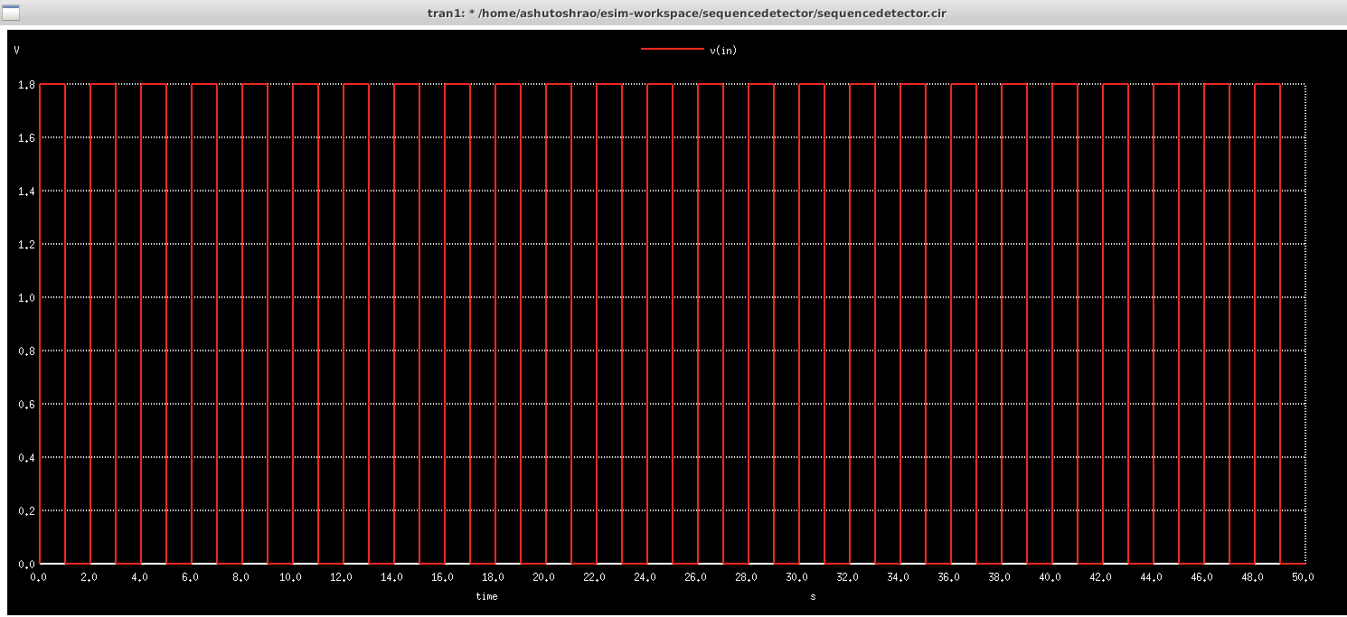
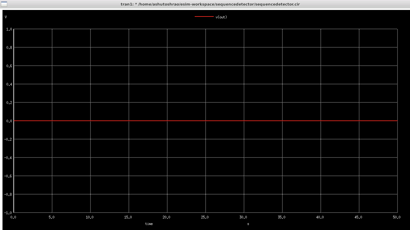
- Output Waveforms
- Author
- Acknowledgements
- References
An FSM is an abstract machine that can exist in only one of a finite number of states at a time. A Moore FSM is one which depends only on the value of present state and not the value of input. A sequence detector is a circuit that takes an input string of bits and generates an output ‘HIGH’ when the target sequence has been detected. Analog input from a CMOS inverter is fed into this digital block and output is observed

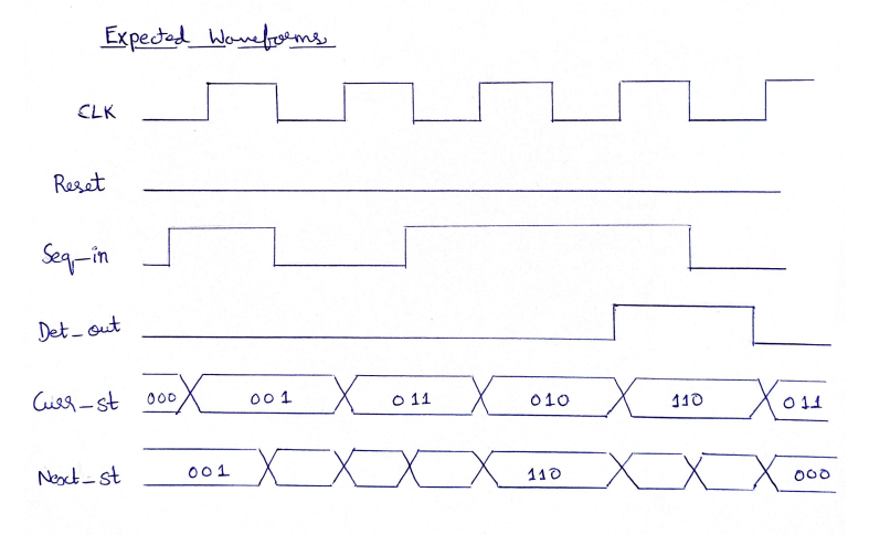

In this paper, a Finite State Machine based sequence detector is proposed. This is a Moore based FSM, where the output is only dependent on the present state. This FSM block is a digital block consisting of three inputs, which are clock, sequence_in and reset. It has one output, the detector_out. This is coded in Verilog. For the analog part, a CMOS inverter is implemented using MOS transistors. The voltage is supplied to the CMOS inverter. The output of the inverter is fed into an ADC block (Analog-to-Digital). The output from this block is passed as input to the FSM digital block along with additional voltage supplies for the clock and reset. The output of the FSM block will be a single output which goes high when the required sequence is detected. The CMOS inverter will be made up of pmos and nmos. The FSM to be implemented will be a 1011 sequence detector. When this particular sequence is detected, the detector_out will show an output of 1. This is passed through a DAC block (Digital-to-Analog), from which the output voltage is measured.

eSim
It is an Open Source EDA developed by FOSSEE, IIT Bombay. It is used for electronic circuit simulation. It is made by the combination of two software namely NgSpice and KiCAD. For more details refer:
NgSpice
It is an Open Source Software for Spice Simulations. For more details refer:
http://ngspice.sourceforge.net/docs.html
Makerchip
It is an Online Web Browser IDE for Verilog/System-verilog/TL-Verilog Simulation. For more details refer:
Verilator
It is a tool which converts Verilog code to C++ objects. For more details refer:
https://www.veripool.org/verilator/

module Sequence_Detector_MOORE_Verilog(sequence_in,clock,reset,detector_out);
input clock; // clock signal
input reset; // reset
input sequence_in; // input
output reg detector_out; // output of the sequence detector
parameter  Zero=3'b000,
           One=3'b001,
           OneZero=3'b011,
           OneZeroOne=3'b010,
           OneZeroOneOne=3'b110;
reg [2:0] current_state, next_state;

// sequential memory of the Moore FSM
always @(posedge clock, posedge reset)
begin
 if(reset==1)
 current_state <= Zero;// when reset=1, reset the state of the FSM to "Zero" State
 else
 current_state <= next_state;
end

// combinational logic of the Moore FSM to determine next state
always @(current_state,sequence_in)
begin
 case(current_state)
 Zero:begin
  if(sequence_in==1)
   next_state = One;
  else
   next_state = Zero;
 end
 One:begin
  if(sequence_in==0)
   next_state = OneZero;
  else
   next_state = One;
 end
 OneZero:begin
  if(sequence_in==0)
   next_state = Zero;
  else
   next_state = OneZeroOne;
 end
 OneZeroOne:begin
  if(sequence_in==0)
   next_state = OneZero;
  else
   next_state = OneZeroOneOne;
 end
 OneZeroOneOne:begin
  if(sequence_in==0)
   next_state = OneZero;
  else
   next_state = One;
 end
 default:next_state = Zero;
 endcase
end

// combinational logic to determine the output of the Moore FSM
always @(current_state)
begin
 case(current_state)
 Zero:   detector_out = 0;
 One:   detector_out = 0;
 OneZero:  detector_out = 0;
 OneZeroOne:  detector_out = 0;
 OneZeroOneOne:  detector_out = 1;
 default:  detector_out = 0;
 endcase
end
endmodule\TLV_version 1d: tl-x.org
\SV
/* verilator lint_off UNUSED*/ /* verilator lint_off DECLFILENAME*/ /* verilator lint_off BLKSEQ*/ /* verilator lint_off WIDTH*/ /* verilator lint_off SELRANGE*/ /* verilator lint_off PINCONNECTEMPTY*/ /* verilator lint_off DEFPARAM*/ /* verilator lint_off IMPLICIT*/ /* verilator lint_off COMBDLY*/ /* verilator lint_off SYNCASYNCNET*/ /* verilator lint_off UNOPTFLAT */ /* verilator lint_off UNSIGNED*/ /* verilator lint_off CASEINCOMPLETE*/ /* verilator lint_off UNDRIVEN*/ /* verilator lint_off VARHIDDEN*/ /* verilator lint_off CASEX*/ /* verilator lint_off CASEOVERLAP*/ /* verilator lint_off PINMISSING*/ /* verilator lint_off BLKANDNBLK*/ /* verilator lint_off MULTIDRIVEN*/ /* verilator lint_off WIDTHCONCAT*/ /* verilator lint_off ASSIGNDLY*/ /* verilator lint_off MODDUP*/ /* verilator lint_off STMTDLY*/ /* verilator lint_off LITENDIAN*/ /* verilator lint_off INITIALDLY*/
//Your Verilog/System Verilog Code Starts Here:
module ashutosh_seqdet(sequence_in,clock,reset,detector_out);
input clock; // clock signal
input reset; // reset
input sequence_in; // input
output reg detector_out; // output of the sequence detector
parameter Zero=3'b000,
One=3'b001,
OneZero=3'b011,
OneZeroOne=3'b010,
OneZeroOneOne=3'b110;
reg [2:0] current_state, next_state;
// sequential memory of the Moore FSM
always @(posedge clock, posedge reset)
begin
if(reset==1)
current_state <= Zero;// when reset=1, reset the state of the FSM to "Zero" State
else
current_state <= next_state;
end
// combinational logic of the Moore FSM to determine next state
always @(current_state,sequence_in)
begin
case(current_state)
Zero:begin
if(sequence_in==1)
next_state = One;
else
next_state = Zero;
end
One:begin
if(sequence_in==0)
next_state = OneZero;
else
next_state = One;
end
OneZero:begin
if(sequence_in==0)
next_state = Zero;
else
next_state = OneZeroOne;
end
OneZeroOne:begin
if(sequence_in==0)
next_state = OneZero;
else
next_state = OneZeroOneOne;
end
OneZeroOneOne:begin
if(sequence_in==0)
next_state = OneZero;
else
next_state = One;
end
default:next_state = Zero;
endcase
end
// combinational logic to determine the output of the Moore FSM
always @(current_state)
begin
case(current_state)
Zero: detector_out = 0;
One: detector_out = 0;
OneZero: detector_out = 0;
OneZeroOne: detector_out = 0;
OneZeroOneOne: detector_out = 1;
default: detector_out = 0;
endcase
end
endmodule
//Top Module Code Starts here:
module top(input logic clk, input logic reset, input logic [31:0] cyc_cnt, output logic passed, output logic failed);
logic clock;//input
logic sequence_in;//input
logic detector_out;//output
//The $random() can be replaced if user wants to assign values
assign clock = $random();
assign sequence_in = ~clk;
ashutosh_seqdet ashutosh_seqdet(.clock(clk), .reset(reset), .sequence_in(sequence_in), .detector_out(detector_out));
\TLV
//Add \TLV here if desired
\SV
endmodule
* /home/ashutoshrao/Desktop/ashutosh_seqdet.cir

* EESchema Netlist Version 1.1 (Spice format) creation date: Sat 01 Oct 2022 02:52:21 PM IST

* To exclude a component from the Spice Netlist add [Spice_Netlist_Enabled] user FIELD set to: N
* To reorder the component spice node sequence add [Spice_Node_Sequence] user FIELD and define sequence: 2,1,0

* Sheet Name: /
U3  Net-_U3-Pad1_ Net-_U3-Pad2_ Net-_U3-Pad3_ Net-_U3-Pad4_ ashutosh_seqdet
U7  Net-_U3-Pad4_ out dac_bridge_1
U6  Net-_SC1-Pad1_ Net-_U4-Pad~_ Net-_U5-Pad~_ Net-_U3-Pad1_ Net-_U3-Pad2_ Net-_U3-Pad3_ adc_bridge_3
scmode1  SKY130mode
v2  in GND pulse
v3  Net-_U4-Pad~_ GND pulse
v4  Net-_U5-Pad~_ GND pulse
v1  Net-_SC1-Pad3_ GND DC
U8  out plot_v1
U1  in plot_v1
U5  Net-_U5-Pad~_ plot_v1
U2  Net-_SC1-Pad1_ plot_v1
U4  Net-_U4-Pad~_ plot_v1
SC1  Net-_SC1-Pad1_ in Net-_SC1-Pad3_ Net-_SC1-Pad3_ sky130_fd_pr__pfet_01v8
SC2  Net-_SC1-Pad1_ in GND GND sky130_fd_pr__nfet_01v8

.end
Vin
Vout
Ashutosh Rao, BTech (Electronics and Communication), PES University, Bangalore, Karnataka, 560085
- Kunal Ghosh (Co-Founder, VLSI System Design Pvt. Ltd.)
- FOSSEE, IIT Bombay
- Steve Hoover (Founder, Redwood EDA)
- Sumanto Kar (eSim Team, FOSSEE, IIT Bombay)
- http://iitb.ac.in/
- https://www.google.co.in/
- https://fossee.in/
- https://spoken-tutorial.org/
- https://www.vlsisystemdesign.com/
- https://www.c2s.gov.in/)
[1] https://www.fpga4student.com
[2] https://www.tutorialspoint.com/vlsi_design
[3] https://www.studytronics.weebly.com/sequence-detectors.html