This is a SIGFOX tutorial for getting started with the HidnSeek GPS Locator. This is a device based upon the ATMega328p with features including:

- GPS Locality
- 3 Axis Accelerometer
- Temperature and Pressure Sensors
- SIGFOX Enabled Module (TD 1207)
- Arduino IDE Compatible
Using the SIGFOX network, the device can broadcast it's payload to the SIGFOX Cloud, where it can be interpreted by a user's server allowing for both Uplink and Downlink messages to be sent. As the network is currently undergoing global rollout, please check our coverage map for details on availability in your region!
This tutorial is aimed at those interested in using the HidnSeek as a development kit.
This tutorial assumes that you are familiar with the Arduino IDE and are using, at least version 1.6.4. This tutorial relies on recent features of the Arduino IDE so please update if you are running an earlier build.
Open up the Arduino IDE and make sure that there are no devices currently connected to your machine.
First of all, you will need to add the board to the Arduino IDE using the Additional Boards Manager. You can find this by clicking on the Arduino IDE, Preferences button. You'll see a text field titled, Additional Boards Manager URLs. Within this field you should add the following link:
https://hidnseek.github.io/hidnseek/package_hidnseek_boot_index.json
This allows the Arduino IDE to automatically find the index files required to build on the HidnSeek Device.
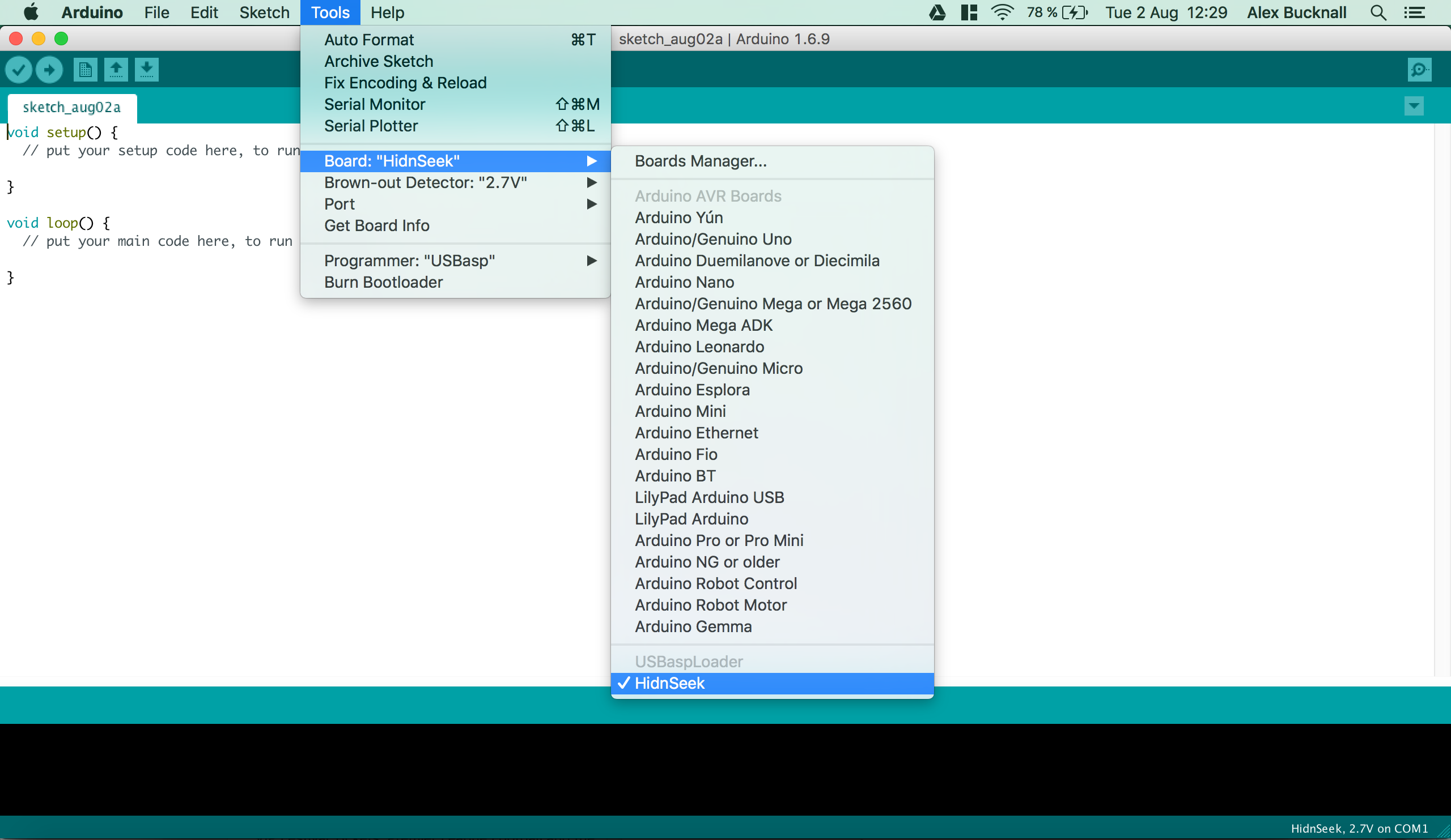
You will now need to install the board. You can do this by navigating to the Board Manager, located under Tools -> Board -> Board Manager. Locate and install USBaspLoader HidnSeek.
Restart the Arduino IDE and check that the board has correctly installed.
There is an up-to-date link to the Windows drivers provided by HidnSeek.
http://www.protostack.com/download/USBasp-win-driver-x86-x64-v3.0.7.zip
The driver will work with Windows XP through to Windows 10 (both 32 and 64 bit editions).
In order to prepare the HidnSeek for the uploading of a sketch, the board must be placed into DFU mode (Device Firmware Update).
If you open the case of the HidnSeek (There are 4 plastic connectors around the edge of the device), you will notice a bank of exposed connections. Short the connections pads labelled R & G and the device will enter DFU mode. You can use a wire to short the pads.

Once the device has entered DFU mode, a red LED will flash rapidly for approximately 30 seconds. During this period of time, a new sketch may be uploaded to the device. If you miss this window, you will have to repeat the process.
In order to utilise the HidnSeek's various sensors, you will need to install the associated libraries. If you head to the following link you will find the libraries already zipped for you. Download the 5 different zipped folders and navigate to the Arduino library manager (Sketch -> Include Library -> Add .ZIP Library). Navigate to the location where you downloaded the files to and choose the .zip file for each library. You will have to repeat this for each library. You should see the following files -
- HidnSeek.zip
- MMA8653.zip
- Barometer.zip
- LowPower.zip
- TinyGPS.zip
Note - You may need to re-zip the files if using OSX or another OS that automatically up-zips files for you
This simple example shows how to use the HidnSeek library to detect movement on the device, counting the number of times the device has moved since the last transmission and send then data over the SIGFOX network.
This could be used as an alarm or a trigger based upon movement such as a door or window opening.
The device is limited to transmit a maximum of approximately 6 times an hour (140~ messages per day) based upon the limitations of the EU Regulations (ETSI 300-220) on the unlicensed 868MHz frequency.
The first important function in the sketch, is the polling of the accelerometer status, accelStatus(). This is needed to determine if the accelerometer has detected moved.
bool accelStatus() { // Checks if Accelerometer has detected movement
    static int8_t x, y, z;

    boolean accelMove = false;
    byte error = accel.update();

    if (error != 0) accelMove = true;
    else {
    accelMove = ((uint8_t)(abs((int8_t)(accel.getX() - x))) > SENSITIVITY) ? true :
                ((uint8_t)(abs((int8_t)(accel.getY() - y))) > SENSITIVITY) ? true :
                ((uint8_t)(abs((int8_t)(accel.getZ() - z))) > SENSITIVITY) ? true : false;
    x = accel.getX();
    y = accel.getY();
    z = accel.getZ();
    }
    return accelMove;
}
The essential part of the of the sketch is the 2-bit transmission with the SIGFOX message. For this, it is easier to call upon the HidnSeek library to access the SIGFOX commands.
void loop(){ // Transmits the number of times the device has been moved since last Sigfox transmission

    unsigned long currentMillis = millis();

    if (currentMillis - previousMillis >= 200) {
        previousMillis = currentMillis;

        if (accelStatus()) {
          if (HidnSeek.isReady()) { // Checks network limit of Sigfox before transmitting the alert
            HidnSeek.send(&counter, sizeof(counter));
            counter = 0;
            digitalWrite(redLEDpin, HIGH);
            delay(200);
            digitalWrite(redLEDpin, LOW);
            delay(800);
          }
          else {
             counter += 1;
            digitalWrite(bluLEDpin, HIGH);
            delay(200);
            digitalWrite(bluLEDpin, LOW);
            delay(800);
          }
        }
    }
}
Please note - the use of isReady() is unideal as it is inefficient as its wastes clock cycles. An ideal solution would be to use interrupts. See the HidnSeek Firmware for an example of how to place the device into a low power state whilst waiting.
You can view the complete sketch here.
This example demonstrates how you can use the HidnSeek's GPS to broadcast the device's location at intervals of once an hour over the SIGFOX network. This sketch is a modification of the Firmware for the HidnSeek as much of the behaviour requires the related sketch functions for battery, GPS, etc. control.
You will need to include the def.h file with your Arduino sketch as this contains many of the core commands needed to communicate with the GPS. This is pulled directly from the HidnSeek firmware so contains additional variable assignments for accelerometer, barometer functionality, etc.
The GPS on the HidnSeek is addressable via a UART connection to pins 0 and 1 on the ATMega328p. This means that a serial connection must be opened in order to send commands to the GPS. The following code snippet shows the function that allows this behaviour.
void gpsCmd (PGM_P s) { // Function to control sending commands directly to the GPS
  int XOR = 0;
  char c;
  while ((c = pgm_read_byte(s++)) != 0) {
    Serial.print(c);
    if (c == '*') break;
    if (c != '$') XOR ^= c;
  }
  if (XOR < 0x10) Serial.print("0");
  Serial.println(XOR, HEX);
}
An example of one of these commands is used to wake up the GPS.
#define PMTK_AWAKE "$PMTK010,001*"
It is also important that all of the components are initalised correctly for use; the GPS requires specific instructions to operate in the mode we desire, NMEA and with a 1 Hz update rate. Initially the Serial port is checked for activity and if this returns true, the GPS modes are set.
bool gpsInit() { // Checks the state of the serial port and set the GPS to output mode to 1 Hz
  boolean GPSready = false;
  digitalWrite(rstPin, HIGH);
  unsigned long startloop = millis();

  while ((uint16_t) (millis() - startloop) < 5000 ) {
    if (Serial.available() > 0 && Serial.read() == '*') {
      GPSready = true;
      break;
    }
    delay(100);
  }
  if (GPSready) {
    gpsCmd(PSTR(PMTK_SET_NMEA_OUTPUT));       // Sets the GPS to NMEA Output Mode
    gpsCmd(PSTR(PMTK_SET_NMEA_UPDATE_1HZ));   // 1 Hz update rate
  } else digitalWrite(rstPin, LOW);
  return GPSready;
}
The next function to review is gpsProcess(). This is where most of the communication between the GPS and the ATMega328p occurs. While this is a relatively large function, the important components are the process of reading from the GPS and parsing the data into a format in which can be sent in a SIGFOX message.
boolean newGpsData = false;
boolean newSerialData = false;
float distance;
unsigned long start = millis();
unsigned int waitime = 2000;

while ((uint16_t) (millis() - start) < waitime)   // Parse GPS data for 2 second
{
  if (Serial.available() > 0) {
    newSerialData = true;
    waitime = 100;
    start = millis();
    blueLEDon;
  }
  while (Serial.available())
  {
    char c = Serial.read();
    // New valid NMEA data available
    if (gps.encode(c))
    {
      newGpsData = true;
    }
  }
}
The retrieved data is then parsed into the separate variables to allow it to be used in the creation of the SIGFOX payload.
if (newGpsData) { // Compute GPS data
    gps.f_get_position(&p.lat, &p.lon, &fix_age);
    if (fix_age == TinyGPS::GPS_INVALID_AGE || fix_age > 5000) fix_age = 1024;
    sat = gps.satellites() == TinyGPS::GPS_INVALID_SATELLITES ? 0 : gps.satellites();
    alt = abs(round(gps.f_altitude()));
    spd = round(gps.f_speed_kmph());

    distance = 1000;
    if (fix_age >> 9) {
        newGpsData = false; // No a real fix detected
        p.lat = previous_lat;
        p.lon = previous_lon;
        serialString(PSTR("recover lat="));
        Serial.print(p.lat, 7);
        serialString(PSTR(", lon="));
        Serial.println(p.lon, 7);
    } else if (abs(p.lat) > 2 && abs(p.lon) > 2) distance = gps.distance_between(p.lat, p.lon, previous_lat, previous_lon);

    if (newGpsData && distance < 5 && syncSat > 20) {
        syncSat = 255;
    }

    if (newGpsData) {
        if (sat < 4 || (abs(p.lat) < 2 && abs(p.lon) < 2)) noSat++;
        else {
            noSat = 0;
            syncSat++; // else syncSat = 0; // increase global variable
        }
        if (sat > 7) syncSat ++;
    }
    else noSat++;
}
else noSat++;
The sports mode and the additional low power functionality of the HidnSeek have been removed to streamline the sketch and make it easier to understand. Take a look at the device firmware to see how these features are utilised.
You can view the complete sketch here.
In order to determine if the GPS data you are collecting is correct, you can use the device's serial port to communicate with a host machine. You will need to use a Serial to USB cable and connect it to the HidnSeek via the GND, RX, TX and 3.3 V connector pads.

In the picture below you can see the HidnSeek connected over a USB to Serial cable. The device itself does not support onboard Serial over USB so an external device is required.

In this specific case the USB to Serial device is using a CP2102 UART to USB Chip from Silabs.
It is also important to note that the GPS shares the same UART pathway as the external head, so when the ATMega328p addresses the GPS, these commands will be seen by the USB to Serial device.
In order to get your HidnSeek connected to the SIGFOX network, you will need to navigate to https://backend.sigfox.com/activate where you will find a selection of our partners who produce SIGFOX enabled Dev Kits. HidnSeek will be one of the available options. Select this option and then choose the SIGFOX Network Operator for your locale, e.g. VT Networks if you plan to use the device in Ireland.
Next you will be asked for the Device ID and PAC. You will be able to find these on the HidnSeek website when you initially set the device up. Entering the PAC number on the SIGFOX Backend will place the device into your control. Follow through the signup process, adding the required details.
Once you've signed up and clicked subscribe, a SIGFOX Backend account will have been created for you. From here you will be able to view information about messages that are sent/received as well as device statistics about SNR (Sigal to Noise Ratio), number of base stations that picked up the message, etc.
Please note that the process of transferring the PAC from HidnSeek to your own account could take up to an hour.
This step is slightly more complicated as we're required to set up an server to communicate with the SIGFOX Cloud and to retrieve any of the messages sent by the HidnSeek.
In the interest of existing tutorials/guides for managing SIGFOX callbacks, it would be useful to check out the Talking Plant Tutorial where it's shown to you how to use node.js to host a server with the purpose of receiving sensor data.
You can configure device callbacks from the SIGFOX Backend.
If you're interested in finding out more about SIGFOX, our technology and the dev kits that are available, you can head to our website to learn more!
- Reference Manual - https://github.com/Bucknalla/Sigfox-Hidnseek-Tutorial/blob/master/Resources/HidnSeek_Manual.pdf
- HidnSeek Original Repository - https://github.com/hidnseek/hidnseek
- Stephane D - HidnSeek