This is an IoT tool that can sample values and control PWM signals over the internet. Today IoT is becoming more and more usefull thanks to the speed of the internet. This IoT tool make it easier for you to sample measurement data, while control e.g. hydraulic cylinder or a DC motor. Very unique thing to use.
This software is made by using:
* GluonHQ JavaFX 8 for Android/iOS/Windows/OSX/Linux
* Spring Boot with Spring security
* JserialComm for communicatation with a microcontroller
* Apache Client
* MySQL Server
* Scene Builder 8
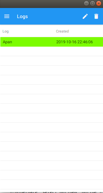
First you can select a file by either create a new one from the pen icon, or select a previous one.
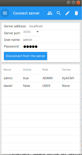
Then you can try to login with your password and username. Also if you have admin rights, then you can create, edit and delete user. Everybody can view who is online and what device they are using.
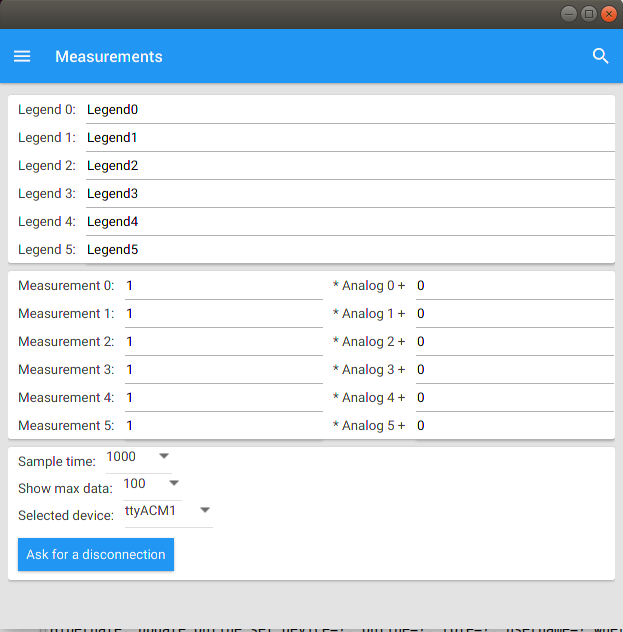
Then before you starting to sample, then you might want to set some calibration and legends to the plot. The calibration follows the y = kx + m formula, where the k is the slope and m is the bias and x is the ADC value from the microcontroller and y is our sampled value. In this case, I say that all legends are indexing from 0 to 5.
Then I starting to sample. To the right you can se a panel with sliders. Here I can control the PWM output for the microcontroller.
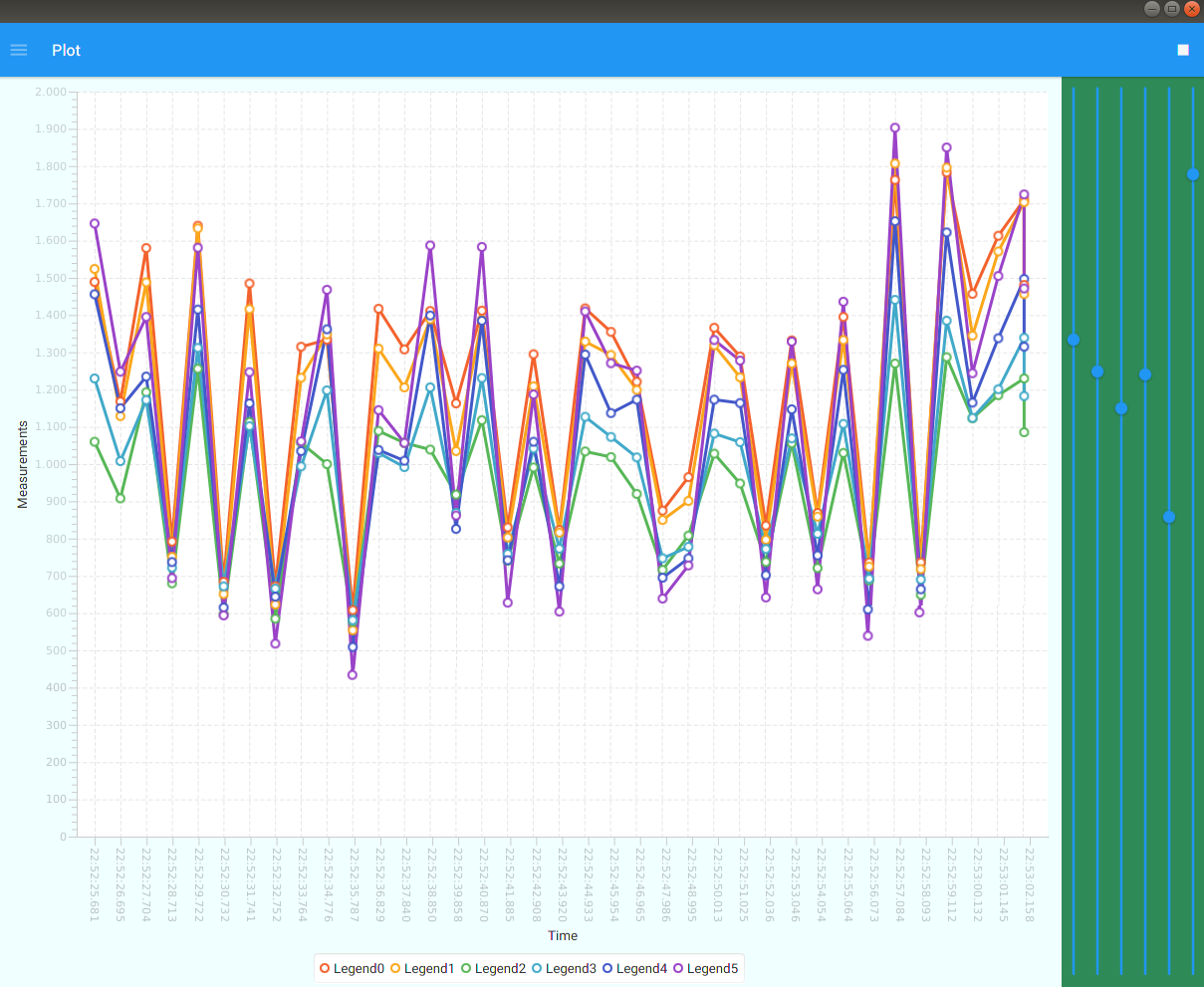
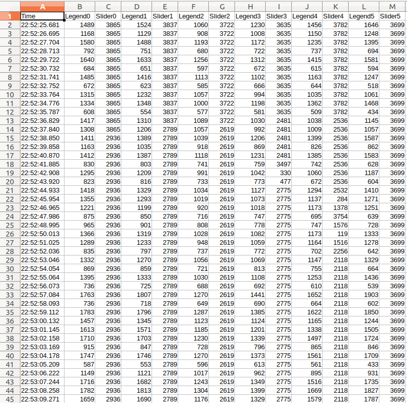
And this is how my output looks like. If I only select few legends, the column width is going to be smaller. So this software is very dynamical and does not use unnecessary legends that are not being used.
If you not planning to use JLogger as a logging tool, you can use it to turn on relays, lamps, pumps etc, or have it as a home equipment to light up the house before you comming home. This IoT-tool have 27 different digital outputs to use and also memory saving so you won't forget which button have been activated before.

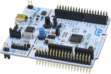
This software is using a microcontroller. I have selected the Nucleo board STM32F446RE.
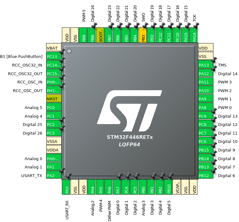
The pinmap looks like this.
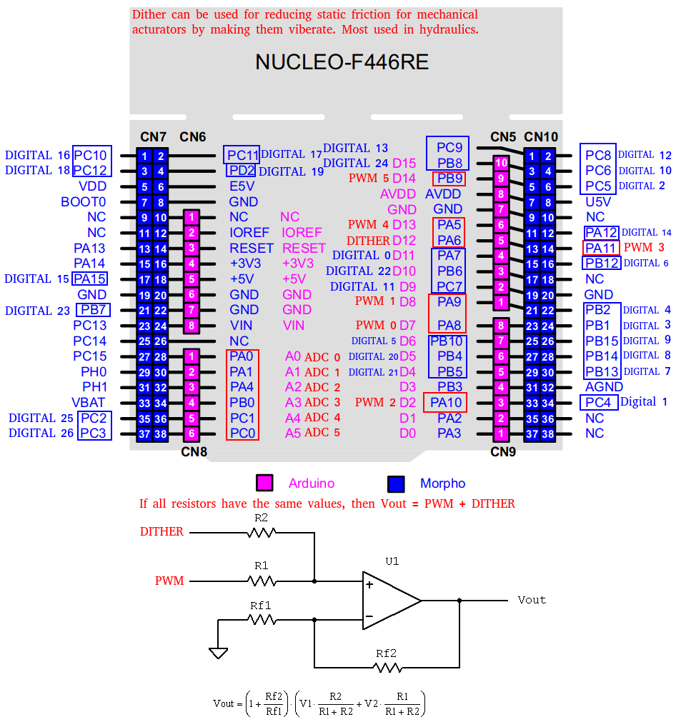
And where are the pins I have used. Notice that there is a Dither PWM pin too. That pin works that it have a constant PWM frequency. Very usefull for hydraulical propotional valves to make the main spool in a floating point all the time = reduce friction. But the PWM dither pin can serves for a simple cheap DC motor as well.
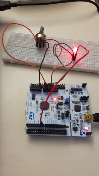
Here I put a LED lamp to the PWM output PA8 and a potentiometer to the analog input A0.
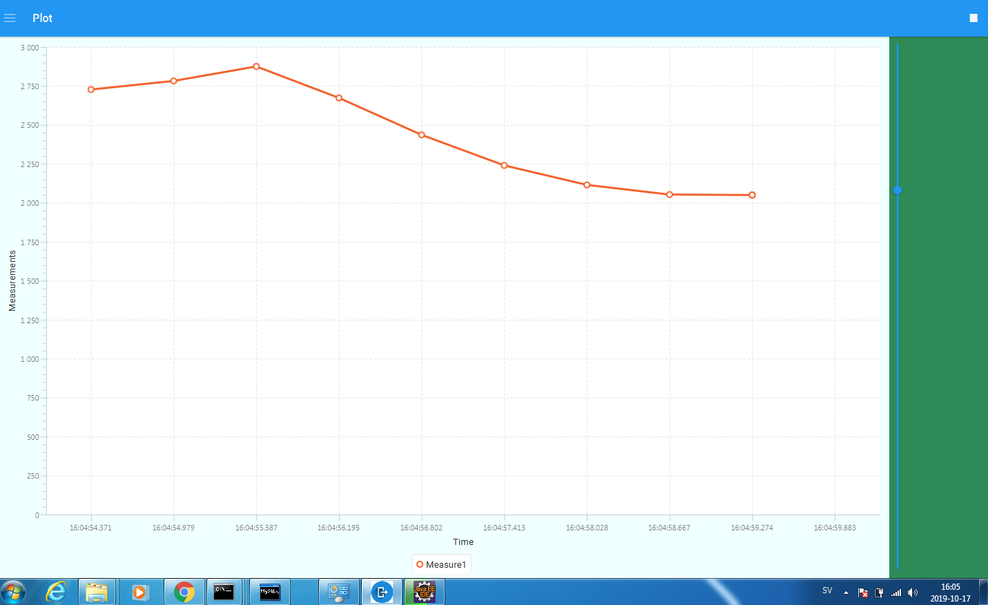
And here is the real time logging display. I have only select one legend, therefore one slider will only be avaiable to use and only one measurement column in the log file.
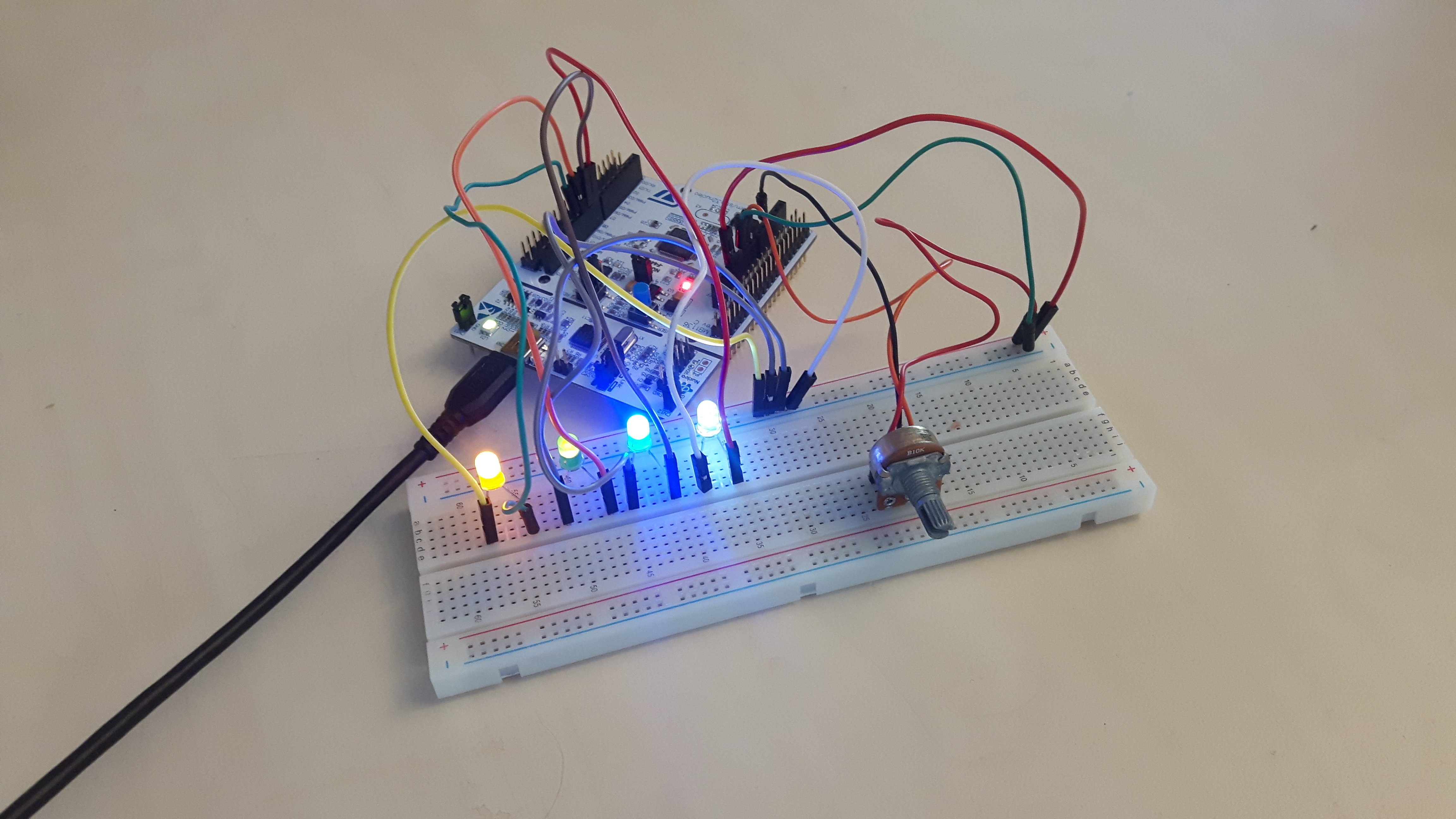
Here is when I have connection from my Android smartphone and I control PWM and digital outputs at the same time, without they affecting each other.
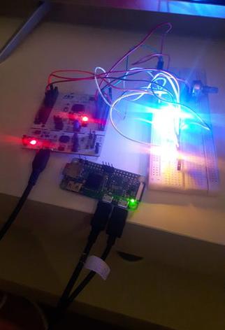
I also tried to implement JLoggerServer onto a Raspberry Pi Zero W and it works! Also I used MariaDB instead of MySQL and I didn't even need to change any database configurations at all. Nothing. Just boot it and run.
Login from my phone
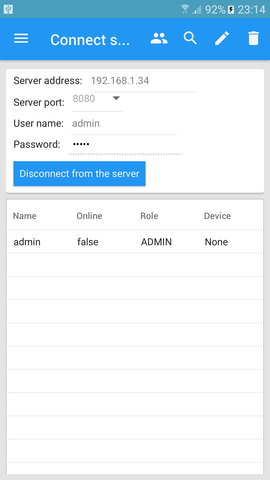
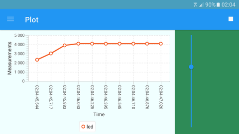
Real time sampling from my phone when JLoggerServer is applied onto Raspberry Pi Zero W
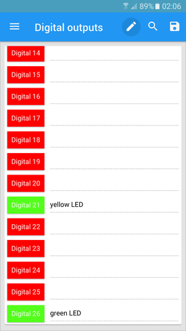
Digials works as well
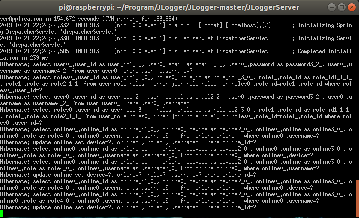
And connect it to PuTTY SSH Client works too
To make JLoggerServer bootable inside a Raspbery. Just paste this code right above exit 0 in /etc/rc.local
Also, you need to implement JLoggerServer as well.

Just follow this manual about make a program bootable at startup onto a Raspberry Pi/Ubuntu/Debian etc.
Step 1: Install MySQL and create a user that have granted rights to create tables and databases
Step 2: Edit the application.properties in the JLoggerServer folder. Here you place the user and password of the MySQL user you just have created. Also the server is configured at port 80. That means you can connect the server from your local area IP address e.g 192.168.x.x. Set port to 8080 if you want to have localhost IP to connect with.
Step 3 (optional): Edit the InitialStartUp.java class in JLoggerServer and change the admin name and admin password to your admin name admin password. Else you can just login with JLogger application with the "admin" and password "admin" and then edit the admin user because you are admin.
Step 4: Install OpenJDK 8 from AdoptOpenJDK and OpenJFX 8. Not OpenJFX 11. Current Java version for mobile GluonHQ is Java 8, but I will update it when GluonHQ releases support for OpenJDK 11.
Step 5: Burn the JLoggerDevice project to a STM32F446RE Nucleo board. I have been using Atollic TrueStudio for this. Use CubeMX if you want to edit the pinout. JLoggerDevice is using DMA on RX-USB and ADC which makes it easier to send values to it and recive ADC values.
Step 6: Start the JLoggerServer with
./gradlew bootRun // For Linux
gradlew bootRun // For Windows
Step 7: Start the JLogger with
./gradlew run // For Linux
gradlew run // For Windows
Or you can just download the Android APK file from here
Step 8(optional): Create a mobile application of JLogger at here if you want to modify.
First you need to use Atollic TrueStudio to import the project. Then you need to use the CubeMX to change the inputs and clock configurations. You don't need to use PWM if you don't want. In the main.c file, you can change where what you want to do. Example if you want to replace the PWM with SPI or something.
/*
 * When we get our message, in this case it will be sizeof(RXData)/sizeof(RXData[0]) bytes of slider inputs.
 * This method will be called
 */
void HAL_UART_RxCpltCallback(UART_HandleTypeDef *huart) {

	// Check if we are going to ONLY set PWM's(0) or set digitals(1). Last RXData have the send state element
	uint8_t send_state = RXData[sizeof(RXData)/sizeof(RXData[0]) - 1];
	if(send_state == 0){
		// Set PWM counters period by convert short -> byte
		htim1.Instance->CCR1 = (uint32_t) ((RXData[0] << 8) | RXData[1]);
		htim1.Instance->CCR2 = (uint32_t) ((RXData[2] << 8) | RXData[3]);
		htim1.Instance->CCR3 = (uint32_t) ((RXData[4] << 8) | RXData[5]);
		htim1.Instance->CCR4 = (uint32_t) ((RXData[6] << 8) | RXData[7]);
		htim2.Instance->CCR1 = (uint32_t) ((RXData[8] << 8) | RXData[9]);
		htim2.Instance->CCR2 = (uint32_t) ((RXData[10] << 8) | RXData[11]);
	}else if(send_state == 1){
		// For digitals only - We start at index 13, which is position 12
		for(uint8_t i = 12; i < sizeof(RXData)/sizeof(RXData[0]); i++){
			if(i == 12){ 	   // Digital 0
				HAL_GPIO_WritePin(GPIOA, GPIO_PIN_7, RXData[i]); //RXData[i] = One or Zero
			}else if(i == 13){ // Digital 1
				HAL_GPIO_WritePin(GPIOC, GPIO_PIN_4, RXData[i]);
			}else if(i == 14){ // Digital 2
				HAL_GPIO_WritePin(GPIOC, GPIO_PIN_5, RXData[i]);
			}else if(i == 15){ // Digital 3
				HAL_GPIO_WritePin(GPIOB, GPIO_PIN_1, RXData[i]);
			}else if(i == 16){ // Digital 4
				HAL_GPIO_WritePin(GPIOB, GPIO_PIN_2, RXData[i]);
			}else if(i == 17){ // Digital 5
				HAL_GPIO_WritePin(GPIOB, GPIO_PIN_10, RXData[i]);
			}else if(i == 18){ // Digital 6
				HAL_GPIO_WritePin(GPIOB, GPIO_PIN_12, RXData[i]);
			}else if(i == 19){ // Digital 7
				HAL_GPIO_WritePin(GPIOB, GPIO_PIN_13, RXData[i]);
			}else if(i == 20){ // Digital 8
				HAL_GPIO_WritePin(GPIOB, GPIO_PIN_14, RXData[i]);
			}else if(i == 21){ // Digital 9
				HAL_GPIO_WritePin(GPIOB, GPIO_PIN_15, RXData[i]);
			}else if(i == 22){ // Digital 10
				HAL_GPIO_WritePin(GPIOC, GPIO_PIN_6, RXData[i]);
			}else if(i == 23){ // Digital 11
				HAL_GPIO_WritePin(GPIOC, GPIO_PIN_7, RXData[i]);
			}else if(i == 24){ // Digital 12
				HAL_GPIO_WritePin(GPIOC, GPIO_PIN_8, RXData[i]);
			}else if(i == 25){ // Digital 13
				HAL_GPIO_WritePin(GPIOC, GPIO_PIN_9, RXData[i]);
			}else if(i == 26){ // Digital 14
				HAL_GPIO_WritePin(GPIOA, GPIO_PIN_12, RXData[i]);
			}else if(i == 27){ // Digital 15
				HAL_GPIO_WritePin(GPIOA, GPIO_PIN_15, RXData[i]);
			}else if(i == 28){ // Digital 16
				HAL_GPIO_WritePin(GPIOC, GPIO_PIN_10, RXData[i]);
			}else if(i == 29){ // Digital 17
				HAL_GPIO_WritePin(GPIOC, GPIO_PIN_11, RXData[i]);
			}else if(i == 30){ // Digital 18
				HAL_GPIO_WritePin(GPIOC, GPIO_PIN_12, RXData[i]);
			}else if(i == 31){ // Digital 19
				HAL_GPIO_WritePin(GPIOD, GPIO_PIN_2, RXData[i]);
			}else if(i == 32){ // Digital 20
				HAL_GPIO_WritePin(GPIOB, GPIO_PIN_4, RXData[i]);
			}else if(i == 33){ // Digital 21
				HAL_GPIO_WritePin(GPIOB, GPIO_PIN_5, RXData[i]);
			}else if(i == 34){ // Digital 22
				HAL_GPIO_WritePin(GPIOB, GPIO_PIN_6, RXData[i]);
			}else if(i == 35){ // Digital 23
				HAL_GPIO_WritePin(GPIOB, GPIO_PIN_7, RXData[i]);
			}else if(i == 36){ // Digital 24
				HAL_GPIO_WritePin(GPIOB, GPIO_PIN_8, RXData[i]);
			}else if(i == 37){ // Digital 25
				HAL_GPIO_WritePin(GPIOC, GPIO_PIN_2, RXData[i]);
			}else if(i == 38){ // Digital 26
				HAL_GPIO_WritePin(GPIOC, GPIO_PIN_3, RXData[i]);
			}
		}
	}

	// Convert ADC values to
	TXData[0] = (uint8_t) (ADCValues[0] >> 8);
	TXData[1] = (uint8_t) (ADCValues[0] & 0xFF);
	TXData[2] = (uint8_t) (ADCValues[1] >> 8);
	TXData[3] = (uint8_t) (ADCValues[1] & 0xFF);
	TXData[4] = (uint8_t) (ADCValues[2] >> 8);
	TXData[5] = (uint8_t) (ADCValues[2] & 0xFF);
	TXData[6] = (uint8_t) (ADCValues[3] >> 8);
	TXData[7] = (uint8_t) (ADCValues[3] & 0xFF);
	TXData[8] = (uint8_t) (ADCValues[4] >> 8);
	TXData[9] = (uint8_t) (ADCValues[4] & 0xFF);
	TXData[10] = (uint8_t) (ADCValues[5] >> 8);
	TXData[11] = (uint8_t) (ADCValues[5] & 0xFF);

	// Send data to JLoggerServer in about 5 milliseconds
	HAL_UART_Transmit(&huart2, TXData, sizeof(TXData)/sizeof(TXData[0]), 5);

	// Listen for a new receive
	HAL_UART_Receive_DMA(&huart2, RXData, sizeof(RXData)/sizeof(RXData[0]));

}
Possible trouble number 1:
If you don't get any logging values, but still connected. That means you don't send any values to the microcontroller or the microcontroller sends back to JLoggerServer, but the server don't understand. Remember, JLogger have HTTP blocking call. If the server don't answer, then the plot is going to stay still. Re-boot the server. To find the issue, have a look at PlotMeasurements.java in JLogger and DeviceController.java in JLoggerServer. They two are working together. If one stops, then the other stops as well. Most of the case, the while loop inside DeviceController.java just loops and never stops because the jSericalComm library don't read any incomming bytes. I'm working hard to make sure that this is happening. I have eliminate lots of bugs that cause the JLoggerServer won't talk to JLoggerDevice