##Improvement for Chinese 50W CO2 Laser Engraving Cutting Machine
This project was born for replace the original electronic chinese card, that moved the laser cutter machine, with RAMPS 1.4 or Arduino CNC Shield .
In addiction i made DIY driver for a much more laser power, take a look at "DIY_Driver_Controller" folder.
Now the laser cutter machine can work with G-Code and Laser-Web app.
The same principle is apply for all CNC/laser machines.
Status: beta
##Schematics We have three types of schematics:
- Chinese original schematic
- RAMPS schematic
- CNC Shield schematic
##Meaning of the laser's signals The original schematic of RAMP at original_diagram reported two differents signals for the laser:
-
Laser Fire, in my case, is the Enable switch for a laser, it's boolean.
In the Chinese original schematic is the green line, from electronic card "LO" to Laser Power Supply "TL". Active low for laser on.
You can also send this signal to the Front Pannel.
In the RAMPS_schematic it's "D5" pin.
In the CNC Shield it's GND if you used LO or 5V is you used TL. -
Laser PWM, in my cose, is the PWM signal to drive the power's ramp.
In the Chinese original schematic is the white line, from Frontal Pannel to Laser Power Supply "IN".In the RAMPS_schematic it's "D4" pin.
In the CNC Shield:
- V3.0 it's "Z+"" pin end stop.
- V3.1 it's "SpnDir" pin.
##RAMPS 1.4 & CNC Shield built in
Remeber, CNC Shield works with GRBL and RAMPS works with Marlin. The only real different are the command: http://goo.gl/lHQ7T
###Diode advise [ RAMPS ONLY ] Ensure that the Power Supply 5v rail is connected to RAMPS I2C 5v pin and that the D1 diode is removed from the RAMPS board as shown in the wiring diagram. If this pin is not connected the laser will fire when you disconnect your ramps board from USB power.
###Motors & Movement config In my Laser cutter machine, Chinese card, i have 2 motors:
- X-Motor, Flexible flat ( Ribbon ) white cable with two Opto Endstops(X and Y).
- Y-Motor, 4 wires cable.
In addiction i have one other motor, Z-Motor, for rise up and down the base.
The motors are: 17hw4410n-03ad-z and 17hw3448n-15ad
I written to baolongmotor and they gave me the datasheet. Take a look in my repository.
###Voltage Ref
Reference Page
For resistors: R100 = 0.1 Ohm or R200 = 0.2 Ohm ecc....
In my case, the formula goes: IRef = Vref/( 8 * 0.1)
For my motors i need about Y-Vref = 0,8 * 0,48A = 0,4V and X-Vref = 0,8 * 1A = 0,8V
###Motor driver It is important for a good movement take a note what types of steppers drivers you will use:
- A4988 = Max. microsteps 16
or - DRV8825 = Max. microsteps 32
for decided how many Jumpers you could use: RAMPS or CNC.
Moreover take a look for a good orientation.
In my case, i buyed two A4988 and i will use only one jumper for 16 microsteps on RAMPS.

If you want to use the single A4988, remember this schematic:
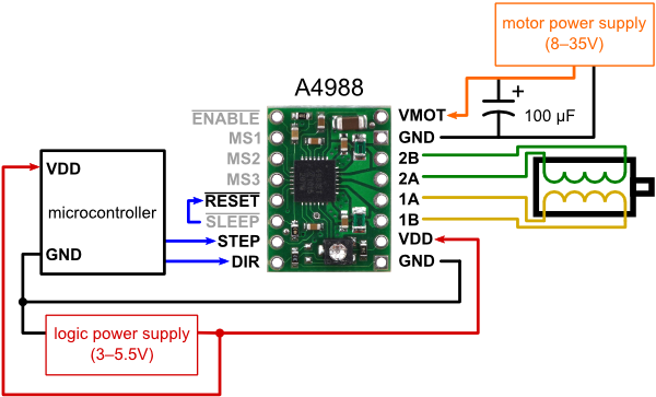
16 microsteps : MS1, MS2, and MS3 must be connected to HIGH ( 5V ).
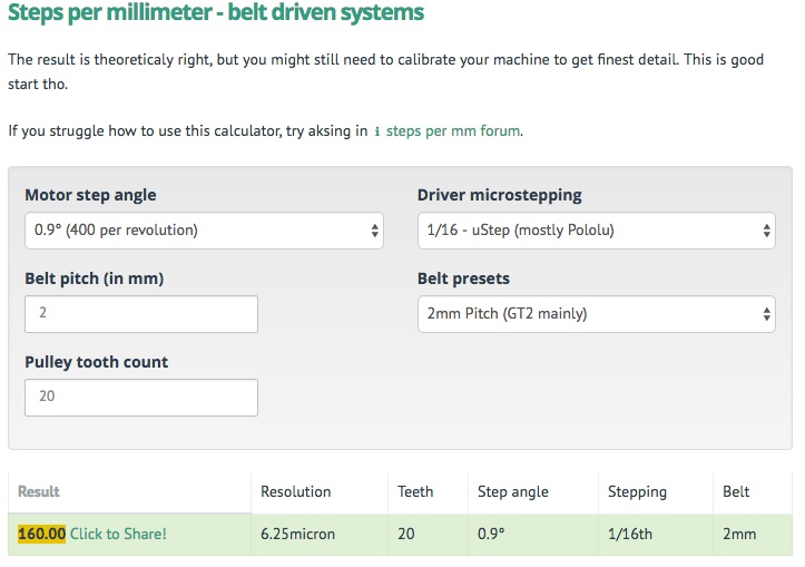
###Movement
We need to obtain the Steps per millimeter. Reference page: http://goo.gl/VHtbYw
You could have two different type of driving systems:
- belt driven systems
- leadscrew driven systems
In my case, i have the first drive system. Well, i need to know the Belt pitch (in mm) and Pulley tooth number.
I used a red pen to count the pulley tooth, and the caliber for belt pitch.
My results, 160.00, save this number for the future:
###EndStop My CNC machine has 2 Optical EndStop. They are wonderful for RAMPS 1.4.
But if you are using CNC Shield, the Optical EndStop are unusable. You must use the meccanical endStop: http://goo.gl/bh0d5C
##Configuring and compilation ###Ramps 1.4:
- Install the arduino software IDE
- Download the Marlin firmware to your PC and extract it
- Start the Arduino IDE:
- Select Tools -> Board -> Arduino Mega 2560 or your microcontroller
- Select the correct serial port in Tools ->Serial Port
- Open Marlin.ino found in the 'Marlin' directory
- Click the Verify/Compile button
- Click the Upload button If all goes well the firmware is uploading and you'll see the led on your arduino flashing wildly. The Arduino IDE will tell you when it has finished uploading.
###CNC shield GRBL v0.9 or greaters (PWM Spindle + Soft limits)
- Install the arduino software IDE
- Load in Arduino IDE the GRBL : https://goo.gl/1aiAtr
- Removed Z axi : https://goo.gl/0uzKYu
- Load edited Gcode.
##LaserWeb2 and UniversalGcodeSender
LaserWeb it's an Host software for Lasercutters/Engravers , it takes many types of files and convert them in Gcode.
NB. take a look at the version you would like to install, each version has different features.
UniversalGcodeSender it takes the Gcode, made by LaserWeb, and send them to Arduino. It's in repository. Set the baud rate to 115200.
This program are used to set all base commands on Gcode or Marlin.
For any Gcode interpreter $$ show the principle machine setting - $ used to set a command .
Marlin code for RAMPS:
- Steps per millimeter
- M92 X160.00 (x, step/mm)
- M92 Y160.00 (x, step/mm)
- Hard-limits / Soft-limits
- ....
GRBL code for CNC:
- Steps per millimeter
- $100=314.961 (x, step/mm)
- $101=314.961 (y, step/mm)
- Hard-limits / Soft-limits / Homing cycle
- $21 = 1
- $20 = 1
- $22 = 1
- Test Homing: (if you need to invert direction use $23)
- $H
- Test the laser with this commands, it's driven by PWM signal in a ranch of 0-1000
- M5 => laser off
- S100 => set laser power to 10% but not fire
- S10 + M3 => set laser power to 1% and fire
##Implementation
###Physical endstop
This machine has only 2 Opto-endstop ( X+ and Y+ ), but for more security i made two supports for two additional physical endspot ( X- and Y-) .
I got two physical endstop on my CD/DVD reader/writer.
Using my 3D printer i made a nice supports, take a look at physical_endstop's folder.
Setting for work in the 2nd quadrant
GRBL
- $H // go at endstops
- G10 L2 P2 X-550Y-380 // set work position (it's different from the machine position) at X550 & Y380 coordinates
- G55 // force the machine for working at work position coordinates now if you do G0 X0Y0 the machine will go at origin (0,0) axis ( lower left corner, Cartesian remember ).
After these settings, remember to put $H and G55 at starter code.
###Endstop Filters
I added pull-up and RC filters on X-Y Endstops for avoid false limits trigger.
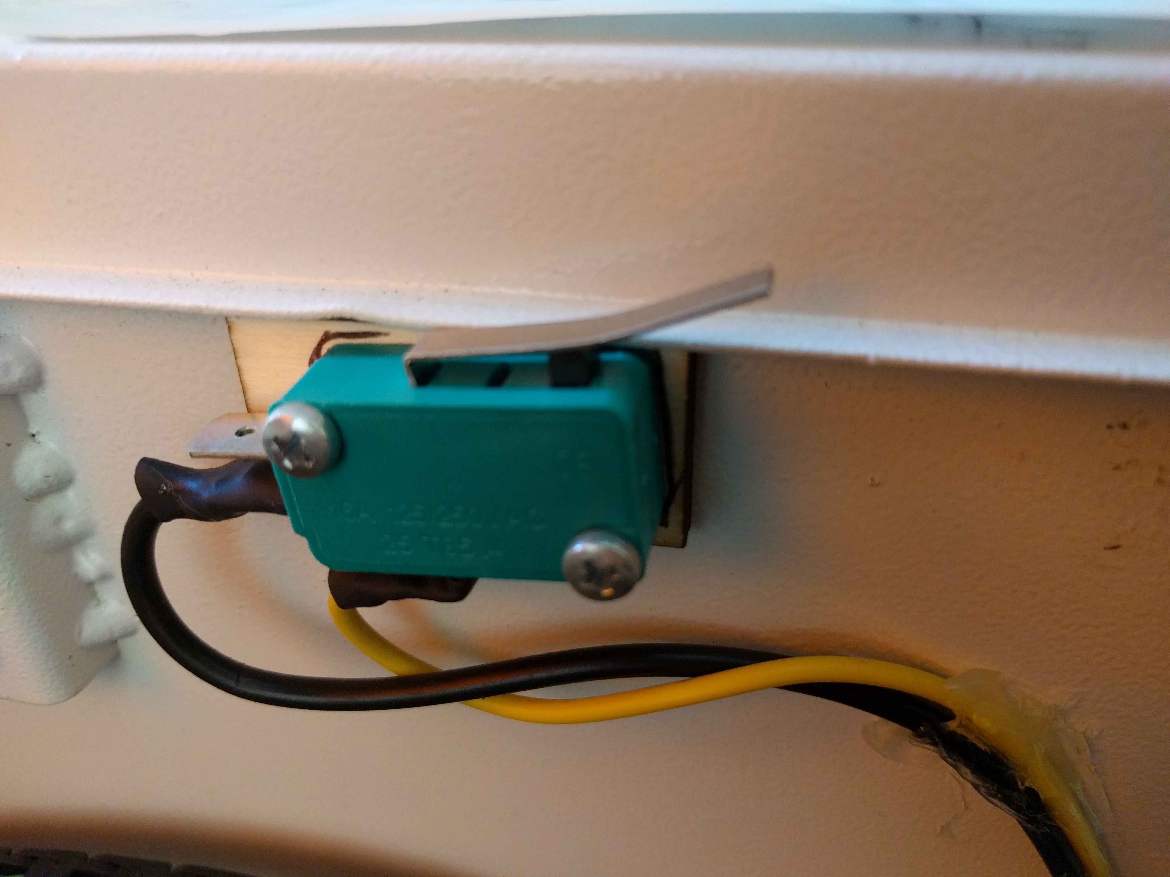
###Top coverage switch
In my machine i have 3 types of security systems:
- Enable/Disable laser in front of machine
- Panic button, disable all machine power
- Water level check
The numbers 1 & 3 must be lower to enable the laser power. They are in series on the same line, from to WP pin on power supply.
For many reasone i would like to add another security system, on Top coverage.
The system it's pretty easy, i added a meccanical switch in the same line of 1 & 3 devices.
##Future implementations
[x] Top coverage switch
[x] Physical endstop
[x] Endstop Filters
[x] DIY driver Control: new schematic, with Optocoupler, for reduce false "Hard-limits"
[ ] Z axis
[ ] Thermal shutdown
soon....