This repo proposes a way to debug microcontrollers by sending high-speed UART data on any of the GPIO.
There are some common methods to debug microcontrollers. We may hook up a debugger, toggle GPIO in test code, print debugging info to a serial port, etc. Here is a table comparing the common methods:
| Method | Pros | Cons |
|---|---|---|
| Hardware Debugger | Full control over code excution and data | Need to pause the code, require hardware support |
| Print on serial | Easy to use and get human-readable info | Not very fast, may need interrupts for a lot of data |
| Toggle GPIOs | Minimal affect to the original code | May need logic analyzer, difficult to send complicated data |
The proposed method is a combination between GPIO toggling and serial printing. Instead of using a hardware UART module, we can use the assembly code to generate the UART signal with precise timing on any GPIO. We can print certain characters in certain places of the code, to know when and how the code is executed, or we can print the value of variables.
The method does not need to use any peripheral or interrupts. And it only takes a few microseconds to run each time. So the impact on the original codes is minimal. However, this method will need some special hardware to get the data from the microcontroller.
Here is a code sample on Arduino Uno (ATmega328P). The baud rate is 5333333 with a 16M CPU clock, and it takes less than 3us to send a byte.
And the code to generate the UART signal.
void tx_on_PB5(char c) {
  //this approach takes 3 clks to send a bit, that is 5333333bit/s for a 16M Arduino
  //use __tmp_reg__ to store SREG to recover interrupt status
  //use __zero_reg__ as temp register, clear at the end of code

  asm volatile("IN __tmp_reg__,__SREG__          \n\t" //backup SREG
               "CLI                              \n\t"

               "IN __zero_reg__,%[ADDR_PORTB]    \n\t"

               "CLT                              \n\t" //1CLK start bit
               "BLD __zero_reg__,5               \n\t" //1CLK
               "OUT %[ADDR_PORTB],__zero_reg__   \n\t" //1CLK

               "BST %[OUT_CHAR],0                \n\t" //1CLK bit 0
               "BLD __zero_reg__,5               \n\t" //1CLK
               "OUT %[ADDR_PORTB],__zero_reg__   \n\t" //1CLK
               "BST %[OUT_CHAR],1                \n\t" //1CLK bit 1
               "BLD __zero_reg__,5               \n\t" //1CLK
               "OUT %[ADDR_PORTB],__zero_reg__   \n\t" //1CLK
               "BST %[OUT_CHAR],2                \n\t" //1CLK bit 2
               "BLD __zero_reg__,5               \n\t" //1CLK
               "OUT %[ADDR_PORTB],__zero_reg__   \n\t" //1CLK
               "BST %[OUT_CHAR],3                \n\t" //1CLK bit 3
               "BLD __zero_reg__,5               \n\t" //1CLK
               "OUT %[ADDR_PORTB],__zero_reg__   \n\t" //1CLK
               "BST %[OUT_CHAR],4                \n\t" //1CLK bit 4
               "BLD __zero_reg__,5               \n\t" //1CLK
               "OUT %[ADDR_PORTB],__zero_reg__   \n\t" //1CLK
               "BST %[OUT_CHAR],5                \n\t" //1CLK bit 5
               "BLD __zero_reg__,5               \n\t" //1CLK
               "OUT %[ADDR_PORTB],__zero_reg__   \n\t" //1CLK
               "BST %[OUT_CHAR],6                \n\t" //1CLK bit 6
               "BLD __zero_reg__,5               \n\t" //1CLK
               "OUT %[ADDR_PORTB],__zero_reg__   \n\t" //1CLK
               "BST %[OUT_CHAR],7                \n\t" //1CLK bit 7
               "BLD __zero_reg__,5               \n\t" //1CLK
               "OUT %[ADDR_PORTB],__zero_reg__   \n\t" //1CLK

               "SET                              \n\t" //1CLK stop bit
               "BLD __zero_reg__,5               \n\t" //1CLK
               "OUT %[ADDR_PORTB],__zero_reg__   \n\t" //1CLK

               "CLR __zero_reg__                 \n\t"
               "OUT __SREG__,__tmp_reg__         \n\t" //restore SREG

               ::[OUT_CHAR]"r" (c), [ADDR_PORTB]"I" (_SFR_IO_ADDR(PORTB)));
}
In short, the assembly code checks each bit of the outgoing byte and then sets the GPIO high or low according to each bit. In the AVR architecture, this is done by using the Bit Copy Storage (T Flag). Each bit is copied from the outgoing byte to the GPIO bit in PORTB, and each bit takes exactly 3 clks. The whole process needs to be done without interruption. No branching, loop, or jump is used, so the code is simpler and faster.
In modern architecture, we need to avoid the flash memory wait states because the timing will be unpredictable. Also, the GPIO operation should be as fast as possible. On Arduino M0 (Arm Cortex-M0+), the function needs to be put in SRAM, and the GPIO should be accessed via IOBUS instead of APB.
Code for several platforms can be found in the uartTxDemoCode folder.
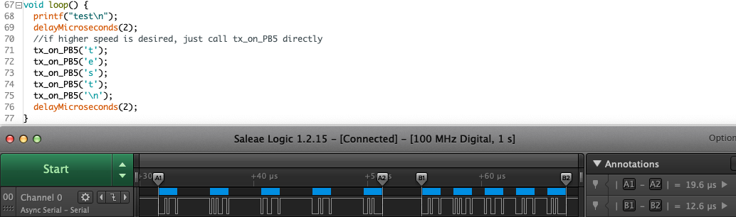
We can use a logic analyzer or a high-speed UART receiver to read the output from the microcontroller. And the 2 methods will both be explained.
Using a logic analyzer is pretty straightforward. Just hook up the output pin to the logic analyzer, and we can capture the signal. And we can see when the data got sent, and we can also see the data if the logic analyzer supports protocol decoding.
The common USB to serial adaptor does not support such high-speed signals. And serial monitor software generally does not allow us to set to such a high baud rate. Chips such as FT2232 and the D2XX driver can do the job, but using the D2XX driver on an expensive chip is not easy.
There is a relatively new chip CH343 that can do UART up to 6Mbps. My chip worked nicely in Win10 with the default driver and Putty.
Here I used a Raspberry Pi Pico (RP2040) to do the receiving job. The whole board costs $4, and there is "Programming with PIO State Machines" that can do UART receive on any GPIO. The PIO module comes with a 16:8 fractional clock divider, and the CPU runs at 125Mhz. So that means the Pico board can receive almost all UART signals generated by a microcontroller.
I used Micropython to write the receiving code. The Pico board will set a GPIO with proper PIO code to receive the UART signal. And once the signal is received, it will forward the data to the USB serial port with timestamps. So any serial monitor will work with the Pico board. The baud rate is hard-coded, but modifying a python script is much easier than compiling a C program.
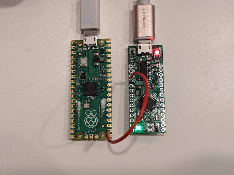
And here I had an Arduino Uno compatible board connected to Pico with an SCN connector jumper wire. The SCN connector is quite handy for temporary connections in pin header holes. The ground wire is not connected because the two boards are connected to the same USB hub.
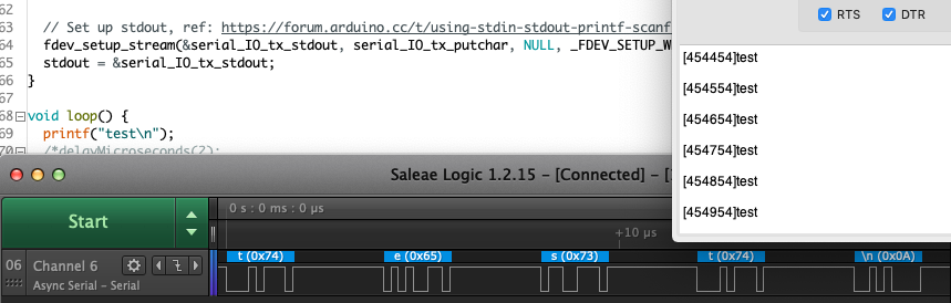
The Pico board can receive the data at high speed and forward the data to the USB serial port. The serial monitor acts as a great addition to the logic analyzer for large amounts of data.
TBD: using an LED on the target board to send debug info. And pick up the info with a sensor.