Author: Xuliang Yu Email: xuliang0912@zju.edu.cn Thanks to Yi Zhou (zhouyi1023@tju.edu.cn) for helping with the translation.
This document serves as a reference guide for the development of single-board millimeter-wave radar based on AWR1243BOOST. To better compatiable with the cascaded radar series, this manual will try to unify the relevant expressions between single-board radar and cascaded radar.
When using this guide, the author's related work in millimeter-wave radar is recommended to be cited.
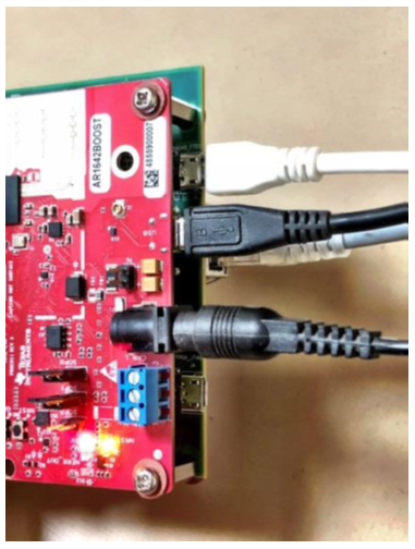
- When using this single-board in the laboratory, there is no need to press the hardware buttons and jumpers. Before formal use, check whether the two UART cables and one Ethernet communication cable of the millimeter-wave radar RF board and the DCA1000 board are correctly connected to the computer. Two power cables need to ensure 5V3A power supply, and remember that the voltage cannot exceed 5V, otherwise it will break through the capacitance of the RF board and possibly cause damage.
The correct wiring method is shown below, and the power supply wiring on the other end of DCA1000 is not visible in this image.
- Download the corresponding version of mmWave Studio from the official website according to the type of the millimeter-wave radar development board. It is necessary to choose the correct version, otherwise the subsequent firmware burning will not be compatible. The official website link is: https://www.ti.com/tool/MMWAVE-STUDIO.
In the "docs" folder of mmwave-studio installation path, such as "C:\ti\mmwave_studio_02_01_01_00\docs", there is usually an official User Guide provided by the manufacturer, and users can complete new board circuit connections and parameter configurations through the User Guide.
- Complete the specific configuration of the port and driver. The method to verify the successful configuration is: select WIN+R, enter "devmgmt.msc" in the CMD window to open the device manager. Under normal circumstances, there will be 4 AR-DEVPACK-EVM-012 and 2 XDS110 CLASS ports in the port list, among which the COM x port of XDS110 CLASS APPLICATION/USER UART needs to be selected for RS232 link configuration in mmwave studio.
- Open mmwave studio 2.1.1.0 and you can choose either manual configuration or script configuration. For manual configuration, refer to the User Guide manual.
4.1 Select SET in the BOARD CONTROL interface under the CONNECTION, and then select CONNECT in the RS232 OPERATIONS interface. The recommended baud rate is 115200. If there are any issues, check if the wiring and 5V power are correctly connected.
4.2 In the BROWSE, select the script, such as the DataCaptureDemo_1243.lua file in C:\ti\mmwave_studio_02_01_01_00\mmWaveStudio\Scripts, and then select RUN to start the script configuration. Wait for the progress bar to load, and you can see that CONNECTED is displayed in green in the SPI CONNECTIVITY field, and the FPGA version in the SENSOR CONFIG column can be displayed normally.
4.3 The basic configuration has been completed. You can use DCA1000 TRIGGER in the SENSOR CONFIG to collect data. Each time you need to press DCA1000 TRIGGER to collect data, otherwise there may be an ERROR. If you need to view the data collection and visualization on the interface, you can select POSTPROC for viewing. (Usually, the bin files collected by data are placed in the POSTPROC folder.)
Troubleshooting
Error 1: Error: Connection failed: Calling_ConnectTarget returned 3; Check if the COM port of the RS232 is selected correctly.
Error 2: MSS POWER UP; Power supply current is insufficient to drive the board, so it is recommended to restart the board and studio for re-burning. In addition, after each successful burn, a restart is required before burning again. Apart from power supply issues, it could also be a contact problem. Check if the JPEG connector of DCA1000 and AWRXXXX is tightened. If all of the above issues have been checked, then check the firmware version of XDS and AR. XDS firmware download can refer to: http://software-dl.ti.com/ccs/esd/documents/xdsdebugprobes/emu_xds_software_package_download.html
Error 3: DCA1000 cannot obtain the FPGA version information; check if the firewall is closed and if the gigabit network card is configured.
Other errors can refer to the DCA1000 DEBUG manual.
Here, we mainly interpret the relevant statements and their meanings in the LUA file and introduce a parameter estimation and configuration tool.
First, let's introduce the mmWave Sensing Estimator, an official calculator from TI, which can configure the parameters of mmWave radar based on different application scenarios.
The tool link is as follows: https://dev.ti.com/gallery/view/1792614/mmWaveSensingEstimator/ver/1.3.0/
Parameter Explanation:
Short Range Default and Long Range Default: the former is based on short-range high-resolution applications for detecting humans; the latter is based on long-range applications and can be used to monitor vehicles.
Device Specific Parameters: Select the mmWave radar model and the receive/transmit antenna.
Board Specific Parameters: Select the transmit gain and receive gain.
Regulatory Restrictions: Select the frequency range (GHz), maximum bandwidth (MHz), and transmit power (dBm).
Scene Parameters: Can be used to refine the radar's application scenario, and can configure a wide range of indicators for different scenarios. One parameter will affect another parameter, and the maximum detection range will affect distance resolution. (In this section, you can set the maximum detection speed, maximum detection distance, as well as speed and distance resolution, and target detection types.)
Additional Parameters: Here, we can further consider indicators such as detection loss, system loss, and detection signal-to-noise ratio.
Outputs and Chirp Design: Provides very detailed Chirp configuration information (including slope, sampling rate, bandwidth, etc.), and is the best tool for novices to configure radar.
Below, we mainly use comments to analyze the meaning of specific code blocks.
--[[
    The following three lines of code are not present in the Lua file provided by TI, but they are indeed meaningful. We know that when using TI's radar development board, mmwave studio cannot be avoided. Every time the radar is powered on, mmwave studio needs to be started, and the set and connect buttons need to be clicked to complete the initialization of the board before clicking the RUN button to burn the LUA file to complete parameter configuration.

    This processing is not a big problem, but it seems cumbersome. Can the two steps be integrated to directly burn the Lua file? That is, can I directly burn the Lua file after opening mmwave studio to complete one-click configuration? Of course it can be done, but I won’t talk about how to achieve this process for now. The following mainly analyzes the meaning of the code block.

    By now, you should understand that the following three statements are used to implement the "start mmwave studio and click set and connect" these two steps.
]]

--[[
    ar1.FullReset()
    ar1.SOPControl(2)
    --ar1.Connect(4,115200,1000)
]]

info = debug.getinfo(1,'S');
-- Get the root directory of the current file, usually C:\ti\mmwave_studio_02_01_01_00\mmWaveStudio\Scripts\DataCaptureDemo_1243.lua
file_path = (info.source);
-- There is usually an @ symbol when returning, which needs to be replaced with a space below.
file_path = string.gsub(file_path, "@","");
file_path = string.gsub(file_path, "DataCaptureDemo_1243.lua","");
-- If you modify the name of the Lua file, you also need to modify the name of the Lua file here. Otherwise, regular matching will fail and information cannot be read.

fw_path   = file_path.."..\\..\\rf_eval_firmware"
-- fw_path is the path to save the MSS and BSS file files, .. means to return to the previous directory, 2.. means to range to the previous 2-level directory.

--ADC_Data file path
data_path     = file_path.."..\\PostProc"
adc_data_path = "C:\\ti\\mmwave_studio_02_01_01_00\\mmWaveStudio\\PostProc\\adc_data.bin"
--[[
    Modify the data_path path to "H:\\RadarProcessing\\RawData"
    Modify the adc_data_path path to "H:\\RadarProcessing\\RawData\\adc_data.bin"
    Without calling PostPROC, the adc_data_raw.bin file will appear in the folder, and after calling POSTPROC, the adc_data_raw.bin file disappears, and the adc_data.bin file appears. In the 2.1.1.0 version of studio, the two are the same.
]]

ar1.CaptureCardConfig_StartRecord("H:\\RadarProcessing\\RawData\\adc_data_1.bin", 1)
RSTD.Sleep(1000)
RSTD.Sleep(5000)  -- The delay is long enough to start the next data acquisition
ar1.CaptureCardConfig_StartRecord("H:\\RadarProcessing\\RawData\\adc_data_2.bin", 1)
RSTD.Sleep(1000)
RSTD.Sleep(5000) -- The delay is long enough to start the next data acquisition


-- The following code will process the RAW ADC DATA after data acquisition is completed
ar1.StartMatlabPostProc(adc_data_path)
RSTD.Sleep(10000)
WriteToLog("Please wait for a few seconds for matlab post processing .....!!!! \n", "green")
-- This section is only analyzing the part related to the AWR1243 millimeter wave radar
-- The following are configurations related to each chirp

elseif((partId == 1243) or (partId == 1443)) then
    if(ar1.ProfileConfig(0, 77, 100, 6, 60, 0, 0, 0, 0, 0, 0, 60.012, 0, 1024, 20000, 0, 0, 30) == 0) then
        WriteToLog("ProfileConfig Success\n", "green")
    else
        WriteToLog("ProfileConfig failure\n", "red")
    end

-- Call ProfileConfig function with the following parameters: Profile Id, Start Freq, Idle Time, ADC Start Time, Ramp End Time
-- The following six 0s are for Pwr Backoff and phase for TX0, TX1, and TX2 respectively
-- 60.012 is the frequency slope, 0 is TX START TIME, 1024 is ADC sampling points, 20000 is ADC sampling rate, and 30 is the antenna gain
-- The following code block is used to configure the antenna transmission sequence as TX0, TX2, TX1, where TX2 is the vertical antenna, and TX0 and TX1 are horizontal antennas.
-- Transmit antenna TX0 in the first sequence: 1 0 0
if (ar1.ChirpConfig(0, 0, 0, 0, 0, 0, 0, 1, 0, 0) == 0) then
    WriteToLog("ChirpConfig Success\n", "green")
else
    WriteToLog("ChirpConfig failure\n", "red")
end
-- Transmit antenna TX2 in the second sequence: 0 1 0
if (ar1.ChirpConfig(2, 2, 0, 0, 0, 0, 0, 0, 1, 0) == 0) then
    WriteToLog("ChirpConfig Success\n", "green")
else
    WriteToLog("ChirpConfig failure\n", "red")
end
-- Transmit antenna TX1 in the third sequence: 0 0 1
if (ar1.ChirpConfig(1, 1, 0, 0, 0, 0, 0, 0, 0, 1) == 0) then
    WriteToLog("ChirpConfig Success\n", "green")
else
    WriteToLog("ChirpConfig failure\n", "red")
end
-- The following code block is related to the configuration of chirp groups and frame information.
if (ar1.FrameConfig(0, 2, 200, 64, 40, 0, 0, 1) == 0) then
    WriteToLog("FrameConfig Success\n", "green")
else
    WriteToLog("FrameConfig failure\n", "red")
end

--[[
0 represents START CHIPR TX, 2 represents END CHIRP TX
200 represents the number of frames (No of Frames), 64 represents the number of Chirps per frame
PERIODICITY is the frame period, set to 40ms. If the number of frames and chirps need to be modified, the period must be adjusted accordingly.
TRIGGER DDELAY is set to 0, DUMMY CHIRPS is also set to 0
]]Above, we have almost been able to achieve the effect of freeing our hands and not having to press buttons in mmwave studio using a lua file, but in reality, there is still one problem: don't we need to click set and connect before we can click RUN to burn the lua file with one click? Can I just burn the lua file without clicking anything? How can this be achieved?
In fact, we need to use a client communication tool called RtttNetClient, which can be found in the path C:\ti\mmwave_studio_02_01_01_00\mmWaveStudio\Clients. We can establish an RSTD connection between Matlab and the communication client, and transmit the lua script file to the client through the protocol to execute the script command and complete the configuration.
So how do we get MATLAB to handshake with RtttNetClient? Please see the following program.
function ErrStatus = Init_RSTD_Connection(RSTD_DLL_Path)
	% 本文件用于和mmWaveStudio建立连接
	% By Xuliang
    if (strcmp(which('RtttNetClientAPI.RtttNetClient.IsConnected'),''))
        % 在打开MATLAB后首先运行本代码
        disp('Adding RSTD Assembly');
        RSTD_Assembly = NET.addAssembly(RSTD_DLL_Path);
        if ~strcmp(RSTD_Assembly.Classes{1},'RtttNetClientAPI.RtttClient')
            disp('RSTD Assembly not loaded correctly. Check DLL path');
            ErrStatus = -10;
            return
        end
        Init_RSTD_Connection = 1;
    elseif ~RtttNetClientAPI.RtttNetClient.IsConnected()
        Init_RSTD_Connection = 1;
    else
        Init_RSTD_Connection = 0;
    end

    if Init_RSTD_Connection
        disp('Initializing RSTD client');
        ErrStatus = RtttNetClientAPI.RtttNetClient.Init();
        if (ErrStatus ~= 0)
            disp('Unable to initialize NetClient DLL');
            return;
        end
        disp('Connecting to RSTD client');
        ErrStatus = RtttNetClientAPI.RtttNetClient.Connect('127.0.0.1',2777);
        if (ErrStatus ~= 0)
            disp('Unable to connect to mmWaveStudio');
            disp('Reopen port in mmWaveStudio. Type RSTD.NetClose() followed by RSTD.NetStart()');
            return;
        end
        pause(1);
    end
    disp('Sending test message to RSTD');
    Lua_String = 'WriteToLog("Running script from MATLAB\n", "green")';
    ErrStatus = RtttNetClientAPI.RtttNetClient.SendCommand(Lua_String);
    if (ErrStatus ~= 30000)
        disp('mmWaveStudio Connection Failed');
    end
    disp('Test message success');
end
Note that the above program only initializes and establishes communication between MATLAB and the mmwave studio client, and does not execute the Lua file burning process. Now, we need to define a "send parameter configuration program" in MATLAB to tell RtttNetClient which Lua file to burn for parameter configuration.
function RadarConfigure
	% 功能:执行参数配置lua文件烧录
	% By Xuliang
    addpath(genpath('.\'))
    RSTD_DLL_Path = 'C:\ti\mmwave_studio_02_01_01_00\mmWaveStudio\Clients\RtttNetClientController\RtttNetClientAPI.dll';
    ErrStatus = Init_RSTD_Connection(RSTD_DLL_Path);
    if (ErrStatus ~= 30000)
        disp('Error inside Init_RSTD_Connection');
        return;
    end
    strFilename = 'C:\\ti\\mmwave_studio_02_01_01_00\\mmWaveStudio\\Scripts\\DataCaptureDemo_1243.lua';
    Lua_String = sprintf('dofile("%s")',strFilename);
    ErrStatus = RtttNetClientAPI.RtttNetClient.SendCommand(Lua_String);
end
After the parameter configuration is completed, we need to collect data, so how do we collect data? We need to continue to define a "data collection program" in Matlab to tell RtttNetClient to start collecting data and how to name the collected data. According to the traditional TI data collection method, we usually have to rename the bin files in the folder after collecting the data, and then start the next round of data collection, which can be annoying! Now you just need to pass in data_name in the following program, and the data collected by DCA1000 will be automatically placed in the specified data folder, which can help improve the experimental efficiency.
function SendCaptureCMD(data_name)
    % Function: Send commands from MATLAB to mmWave to control DCA to collect and transmit data
	% By Xuliang
    root_path = 'H:\MyDataset\DatasetFile\'; % Root path name
    data_path = strcat(root_path,data_name);
    mkdir(data_path); % Create folder

    %% Modify the script file for collecting data
    str1 = strcat('adc_data_path="H:\\MyDataset\\DatasetFile\\',data_name,'\\adc_data.bin"');  % bin file directory
    str = [str1,"ar1.CaptureCardConfig_StartRecord(adc_data_path, 1)","RSTD.Sleep(1000)","ar1.StartFrame()"];
    fid = fopen('C:\ti\mmwave_studio_02_01_01_00\mmWaveStudio\Scripts\CaptureData1243.lua','w');
    for i = 1:length(str)
        fprintf(fid,'%s\n',str(i));
    end
    fclose(fid);  % Close file

    %% Configure radar data acquisition
    addpath(genpath('.\'))
    % Initialize mmWaveStudio .NET connection
    RSTD_DLL_Path = 'C:\ti\mmwave_studio_02_01_01_00\mmWaveStudio\Clients\RtttNetClientController\RtttNetClientAPI.dll';
    ErrStatus = Init_RSTD_Connection(RSTD_DLL_Path);
    if (ErrStatus ~= 30000)
        disp('Error inside Init_RSTD_Connection');
        return;
    end
    strFilename = 'C:\\ti\\mmwave_studio_02_01_01_00\\mmWaveStudio\\Scripts\\CaptureData1243.lua';
    Lua_String = sprintf('dofile("%s")',strFilename);
    ErrStatus = RtttNetClientAPI.RtttNetClient.SendCommand(Lua_String);
end
% Complete execution logic that can be referred to
% An APP or GUI can be used for block management, and the author has implemented it, which is still feasible.


clc;clear;close all;
% run('RadarConfigure.m');   % Execute for the first time, comment it out later

% Data path
root_path = 'H:\MyDataset\DatasetFile\'; % Root path name
data_name = 'TS2'; % Data name
data_path = strcat(root_path,data_name);

adc_file_name = strcat(data_path,'\adc_data_Raw_0.bin'); % Check whether there is a bin file under the folder
SendCaptureCMD(data_name); % Send command to collect dataPlease use the TI official website to find other configuration solutions: https://e2e.ti.com Chinese version: https://e2echina.ti.com