From the beginning, the main idea of this repository was an analysis of the LibGDX functionality and performance, especially in the 3D graphic.
After some exploration, I realized that I need a deep knowledge of 3D graphic basics, mathematical techniques (vectors, matrices, quaternions, etc.) and experience with the OpenGL API in order to build effective 3D applications. After all, this repository created to obtain some experience in 3D graphics.
I've started with the editor for a 3D scenes which can contain the basic functionality to effective and optimized 3D scene creation.
The mainline of this repository is the editor branch(LINK) that will contain the world editor with useful GLSL shaders, utilities, additional custom implementations of the pathfinding system, texture generation, noise generation, shaders and etc.
The significant part of the OpenGL analyzing is its own GLSL shaders implementation in order to interact with the OpenGL rendering process. In each sample, I'm trying to implement everything myself to better understand the OpenGL functionality.
Currently, I've implemented few test examples in order to analyze the general functions, such as vertex transformation and primitive rasterization, coordinate system and projection view, texturing, and light which are performed by 3D graphics hardware using the OpenGL library API.
These scenes based on direct communication with HAL(Hardware Abstraction Layer) provided by LWJGL LINK for Java. Note: To simplify code I've used a LibGDX API. Understanding of the basic the OpenGL functionality and most of the rendering parts were implemented by self.
This example demonstrates basic techniques for working with 3D graphics:
- The Vertex data creation;
- The vertex and fragment shaders implementation using GLSL;
- World transformation;
- Perspective projection;
- Binding the Vertex Data and texture with the Shader Program;
These are the most essential things for working with 3D graphics and understanding the rendering process.
To start drawing something we have to first give OpenGL some input vertex data. OpenGL is a 3D graphics library so all coordinates that we specify in OpenGL are in 3D (x, y, z). OpenGL doesn't simply transform all your 3D coordinates to 2D pixels on your screen; OpenGL only processes 3D coordinates when they're in a specific range between -1.0 and 1.0 on all 3 axes (x, y, z).
We manage this vertex data via so-called Vertex Buffer Objects (VBO LINK) that can store a large number of vertices in the GPU's memory. A Vertex Array Object (VAO LINK) can be bound just like a vertex buffer object and any subsequent vertex attribute calls from that point on will be stored inside the VAO.
The LibGDX provides an API to simplify vertex data creation and binding to VAO. The VertexBufferObjectWithVAO (LINK) provides methods to define the VBO with specific vertex attributes (LINK). An important part of the VertexBufferObjectWithVAO functionality is auto binding an array of vertices to the VAO after initializing or updating the vertex data.
The following example creates VBO(Vertex buffer object) with VAO(Vertex Array Object) in order to define vertex data of square plane:
VertexBufferObjectWithVAO(true, 4, VertexAttribute.Position(), VertexAttribute.TexCoords(0)).apply {
    val vertices = floatArrayOf(
    // Position(x,y,z), Texture coordinates (u,v)
        -1f,  1f, 0f, 0f, 1f, // ╔ upper left corner
        -1f, -1f, 0f, 0f, 0f, // ╚ lower-left corner
         1f, -1f, 0f, 1f, 0f, // ╝ right bottom corner
         1f,  1f, 0f, 1f, 1f) // ╗ upper right corner
        setVertices(vertices, 0, vertices.size)
    }
As result the array contains 4 vertices and each vertex combines from 5 float values (x, y, z, u, v).
Our vertex buffer data is formatted as follows:
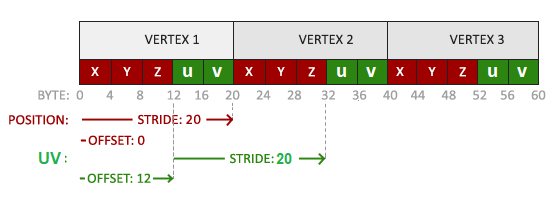
As you can see, the vertices data is a single array with specific Vertex Attributes that used to define the following vertex components:
- VertexAttribute.Position() - the position component(x,y,z);
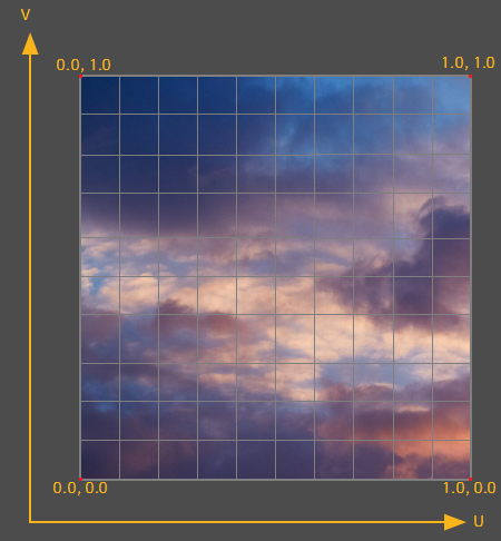
- VertexAttribute.TexCoords(0) - the texture coordinates component(u,v). Coordinates component is a range from 0 to 1 in the x and y axis (remember that we use 2D texture images). Texture coordinates start at (0,0) for the lower-left corner of a texture image to (1,1) for the upper right corner of a texture image:
The OpenGL can work with different types of primitives: points, lines, triangles, etc. The most suitable primitive to build our square plane is a triangle. Our shape has 4 vertices combined from 2 triangles, in order to avoid vertex duplication we need to define a triangle indices:
// Plane mesh separated by two triangles.                   0╔═╗3
// Each triangle contains 3 vertices (0 1 2) and (2 3 0).   1╚═╝2
private fun createIndices() = IndexArray(6).apply {
       setIndices(shortArrayOf(0, 1, 2, 2, 3, 0), 0, 6)
}
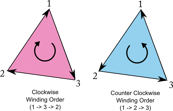
All triangle indices should be defined in counter-clockwise winding order to provide the correct operation of the OpenGL Face culling (LINK).
More detailed about vertex data creation you can read at learnopengl.com
The shader is a program that runs for each specific section of the graphics pipeline. In a basic sense, the shader is a program transforming inputs to outputs. The shader is a very isolated program and can communicate with other shaders via inputs and outputs. Shaders are written in the C-like language GLSL Wiki. GLSL is tailored for use with graphics and contains useful features specifically targeted at vector and matrix manipulation.
The Vertex Shader (LINK) is the programmable Shader stage in the rendering pipeline that handles the processing of individual vertices.
I've implemented the simplest vertex shader we can find: the only thing it should to do is to calculate the position of the vertex considering the combined(viewprojectionmodel) matrix and send the input vertices to the fragment shader without transformation. So, it’s a useless shader and doesn't provide any transformations. But it’s perfect to see the principle of its working.
The the following code snipper of vertex shader:
#version 330 core
layout (location = 0) in vec3 a_position;
layout (location = 1) in vec2 a_texCoord0;
out vec2 texcoord;
uniform mat4 combined;

void main()
{
    gl_Position = combined * vec4(a_position, 1.0f);
    texcoord = a_texCoord0;
}
- a_position - the input value of the vertex coordinates(x,y,z).
- a_texCoord0 - the input value of the texture coordinates(u,v).
- texcoord - the output value of texture coordinates, will be passed to the fragment shader in order to define pixel color.
- combined - a global shader variable for final perspective projection matrix (More detailed informaiton).
To set the output of the vertex shader we have to assign the position data to the predefined gl_Position variable which is a vec4 behind the scenes. gl_Position is a Homogeneous coordinates. Homogeneous coordinates are needed for perspective projection.
The fragment shader is the second and final shader that should be created for rendering a textured plane. The fragment shader is all about calculating the color output of your pixels. The fragment shader only requires one output variable gl_FragColor and that is a vector of size 4 that defines the final color output.
The basic fragment shader:
#version 330 core
in vec2 texcoord;
uniform sampler2D texture_1;

void main()
{
    gl_FragColor = texture2D(texture_1, texcoord);
}
The texture2D function returns a texel, i.e. the (color) value of the texture for the given coordinates. The function has two parameters: the first parameter is the sampler2D uniform the texture is bound to, and the second parameter is the 2-dimensional coordinates(u,v) for the texel lookup.
- texcoord - the input value of the coordinates for texture mapping obtain from vertex shader;
- texture_1 - a global shader variable for single 2D texture;
- gl_FragColor - the output variable of final color value that we should calculate.
A shader program encapsulates a vertex and fragment shader pair linked to form a shader program. The LibGDX provides the own implementation of the ShaderProgram.
The following code demonstrates the process of the Shader Program creation and linking fragment and vertex shaders created before:
final String vertexShader = FileProvider.simple3d_vertex_shader.readString();
final String fragmentShader = FileProvider.simple3d_fragment_shader.readString();
return new ShaderProgram(vertexShader, fragmentShader);
The detailed information about shaders you can find at learnopengl.com
However, to fully understand transformations we first have to delve a bit deeper into vectors, matrices, and transformations. I'm not going to write about it now, so it's better to read the elaborate article at learnopengl.com
To transform the coordinates from one space to the next coordinate space we'll use several transformation matrices of which the most important are the model, view and projection matrix. Our vertex coordinates first start in local space as local coordinates and are then further processed to world coordinates, view coordinates, clip coordinates and eventually end up as screen coordinates.
The following image displays the process and shows what each transformation does:

Detailed information about coordination system and perspective projection you can find at learnopengl.com
Briefly, to start drawing in 3D we'll first create a model matrix. The model matrix consists of translations, scaling and/or rotations we'd like to apply to transform all object's vertices to the global world space. Lest place our plane at (0,0,0). The model matrix then looks like this:
// Plane position and rotation
private val modelMatrix = Matrix4()
    .translate(0f, 0f, 0f)
By multiplying the vertex coordinates with this model matrix we're transforming the vertex coordinates to world coordinates.
Next we need to create a view matrix. We want to move slightly backwards in the scene so the object becomes visible (when in world space we're located at the origin (0,0,0)):
// Camera position and rotation
private val viewMatrix = Matrix4()
    .setToLookAt(Vector3(0f, 0f, 3f), Vector3.Zero, Vector3.Y)
The last thing we need to define is the projection matrix. We want to use perspective projection for our scene so we'll declare the projection matrix like this:
// Camera projection(frustum)
private val projectionMatrix = Matrix4().apply {
    val near = 0.1f
    val far = 10f
    val fov = 67f
    val aspectRation = (Gdx.graphics.width / Gdx.graphics.height).toFloat()
    setToProjection(near, far, fov, aspectRation)
}
All parameters that have been passed to the setToProjection method are responsible for the camera frustum:
The frustum is used to determine what the camera can see. Everything that is inside or intersects with the camera's view-frustum has to be rendered, all the rest can be ignored.
We create a transformation matrix for each of the above-mentioned steps: model, view and projection matrix. After all, we should define the final combined matrix, declared a uniform in the vertex shader and sent the matrix to the shaders where we transform our vertex coordinates.
combinedMatrix.set(projectionMatrix).mul(viewMatrix).mul(modelMatrix)
shader.setUniformMatrix("combined", combinedMatrix)
More detailed information about camera and perspective projection you can read at following articles
The following code represents final rendering method:
fun draw() {
    Gdx.gl.glEnable(GL_DEPTH_TEST)
    Gdx.gl.glClear(GL_COLOR_BUFFER_BIT or GL_DEPTH_BUFFER_BIT)
    shader.begin()
    //Caclulates the combined projection and view matrix.
    combinedMatrix.set(projectionMatrix).mul(viewMatrix).mul(modelMatrix)
    // Setup the combined matrix into uniform variable "combined" in vetex shader.
    shader.setUniformMatrix("combined", combinedMatrix)
    // Bind active GL_TEXTURE_2D to texture Object handle.
    Gdx.gl.glBindTexture(GL_TEXTURE_2D, texture.textureObjectHandle)
    // Bind shape vertices to shader.
    vertices.bind(shader)
    // Draw draw triangles.
    Gdx.gl.glDrawElements(GL_TRIANGLES, vertices.numVertices, GL_UNSIGNED_SHORT, indices.buffer)
    // Unbind vertices.
    vertices.unbind(shader)
    shader.end()
}
The full code of this scene you can find at following link Plane3dScene.kt
I'm sure that you're astonished by the number of various things you need to work in order to implement a simple scene. Actually, the plane from previous scene that rotates around the axis looks pretty simple and primitive, but it's necessary to understand the basic stages of working with the OpenGL. In this part, we will delve into the camera matrices and analyze their logic in detail.
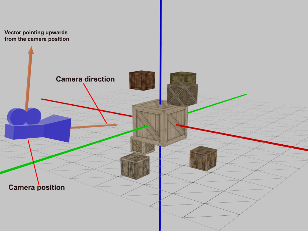
In fact, the OpenGL itself is not familiar with the concept of the camera, but we can try to simulate it. When we're talking about camera/view space we're talking about all the vertex coordinates as seen from the camera's perspective as the origin of the scene: the view matrix transforms all the world coordinates into view coordinates that are relative to the camera's position and direction. To define a camera we need its position in world space, the direction it's looking at and vector pointing upwards from the camera.
Lets define camera view matrix:
private val viewMatrix = Matrix4().apply {
    val position = Vector3(0f, -8f, 1f)
    val target = Vector3(0f, 0f, 0f)
    val direction = Vector3(position).sub(target).nor()
    val right = Vector3.X
    val up = Vector3(direction).crs(right)
    setToLookAt(position, target, up)
}
- position - the camera position in world space;
- target - the camera target point;
- direction - the normalized vector of the camera direction;
- right - a vector that represents the positive x-axis of the camera space;
- up - a vector pointing upwards from the camera position.
In setToLookAt() method we have to specify a camera position, a target position and a vector that represents the up vector in world space.
This image shows the placement of objects in this scene:
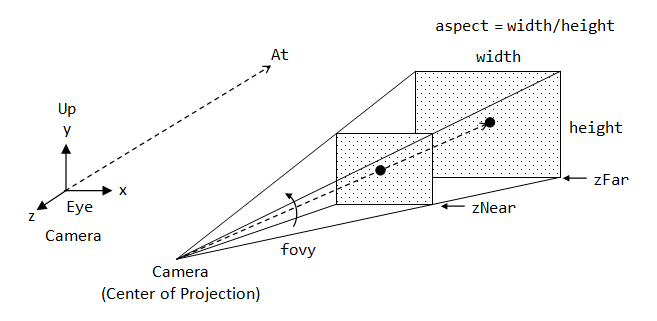
The last thing we need to define for camera is the projection matrix. The projection matrix defines a parameters of a camera frustum. Frustum is a truncated rectangular pyramid used to define the viewable region and its projection onto the screen:
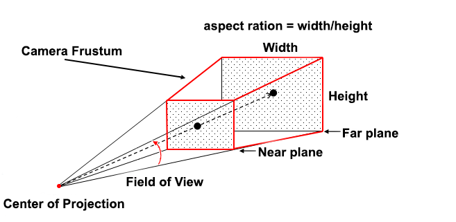
Its first and second parameter set the near and far plane of the frustum. Lets define the near plane distance to 0.1 and the far plane distance to 32.0, because only the vertices between the near and far plane and inside the camera frustum will be rendered. The third parameter defines the fov value(LINK), that stands for field of view(Angle of view) and sets how large the viewspace is. The last parameter sets the aspect ratio which is calculated by dividing the viewport's width by its height.
private val projectionMatrix = Matrix4().apply {
    val near = 0.1f
    val far = 32f
    val fov = 67f
    val aspectRatio = Gdx.graphics.width / Gdx.graphics.height
    setToProjection(near, far, fov, aspectRatio.toFloat())
}
- near - a near plane distance of camera frustum;
- far -a far plane distance of camera frustum;
- fov - the field of view of the height, in degrees;
- aspectRatio - the aspect ratio of the viewport.
More detailed information about the perspective camera you can find at LINK.
At first, we need to create a data class for our cubes that will have its own position, size, and texture:
data class Cube(val position: Vector3, val size: Float = 1f, val texture: Texture) {
    private val vertices: VertexData
    private val indices: IndexData
    private val modelMatrix: Matrix4

    fun draw(shader: ShaderProgram, cameraMatrix: Matrix4) {

    }

    fun dispose() {

}
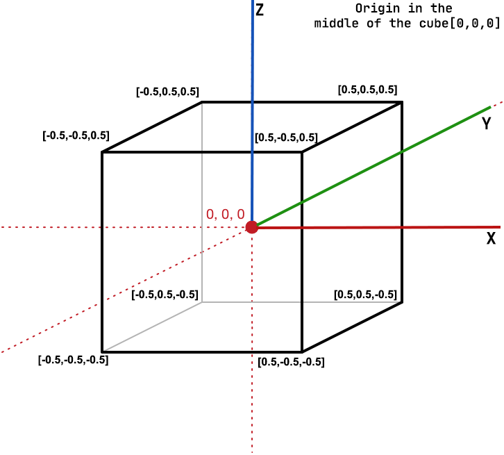
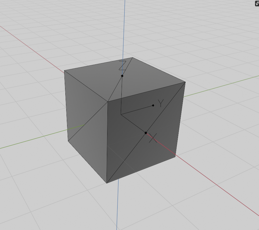
All the cubes have the same vertices, therefore we need to create them once and reuse for each cube. Since we were working with a two-dimensional plane, even in three-dimensional space, and we should extend the 2D plane to a 3D cube. For the cube model, we need to define 24 vertices (6 faces * 4 vertices).
The following image shows the qube in three-dimensional space with edge length equal to 1.0 and origin in middle of the cube:
The following code snippet represents vertices creation:
private fun createVertexData(): VertexData {
    val vertices = floatArrayOf(
    // Bottom face                                 ___________
    -.5f, -.5f, -.5f, 0f, 0f,   //0                |16     17|
    .5f, -.5f, -.5f, 1f, 0f,    //1                |  BACK   |
    .5f, .5f, -.5f, 1f, 1f,     //2                |         |
    -.5f, .5f, -.5f, 0f, 1f,    //3                |19_____18|
    // Top face                         _________________________________
    -.5f, -.5f, .5f, 0f, 0f,    //4     |9       8||7       6||12     13|
    .5f, -.5f, .5f, 1f, 0f,     //5     |   LEFT  ||   TOP   ||  RIGHT  |
    .5f, .5f, .5f, 1f, 1f,      //6     |         ||         ||         |
    -.5f, .5f, .5f, 0f, 1f,     //7     |10_____11||4_______5||15_____14|
    // Left face                                   ___________
    -.5f, .5f, .5f, 1f, 0f,     //8                |23     22|
    -.5f, .5f, -.5f, 1f, 1f,    //9                |  FRONT  |
    -.5f, -.5f, -.5f, 0f, 1f,   //10               |         |
    -.5f, -.5f, .5f, 0f, 0f,    //11               |20_____21|
    // Right face                                  ___________
    .5f, .5f, .5f, 1f, 0f,      //12               |0       1|
    .5f, .5f, -.5f, 1f, 1f,     //13               |  BOTTOM |
    .5f, -.5f, -.5f, 0f, 1f,    //14               |         |
    .5f, -.5f, .5f, 0f, 0f,     //15               |3_______2|
    // Back face
    -.5f, -.5f, -.5f, 0f, 1f,   //16
    .5f, -.5f, -.5f, 1f, 1f,    //17
    .5f, -.5f, .5f, 1f, 0f,     //18
    -.5f, -.5f, .5f, 0f, 0f,    //19
    // Front Face
    -.5f, .5f, -.5f, 0f, 1f,    //20
    .5f, .5f, -.5f, 1f, 1f,     //21
    .5f, .5f, .5f, 1f, 0f,      //22
    -.5f, .5f, .5f, 0f, 0f      //23
    )
    return VertexBufferObjectWithVAO(true, vertices.size,
    VertexAttribute.Position(),VertexAttribute.TexCoords(0)).apply {
        setVertices(vertices, 0, vertices.size)
    }
}
In our understanding, each face of the cube is described by 4 vertices. But, the OpenGL interprets the vertices as a sequence of triangles, points, or lines. For us, the most suitable privative is a triangle formed by 3 vertices. For defining triangles we will use indices. The indices control what order the vertices are received in, and indices can specify the same array element more than once.
Lets define the qube indices:
private fun createIndices(): IndexData {
    val indices = shortArrayOf(
    0, 1, 2, 2, 3, 0,       // Bottom
    4, 5, 6, 6, 7, 4,       // Top
    8, 9, 10, 10, 11, 8,    // Left
    12, 13, 14, 14, 15, 12, // Right
    16, 17, 18, 18, 19, 16, // Back
    20, 21, 22, 22, 23, 20  // Front
    )
    return IndexArray(indices.size).apply {
    setIndices(indices, 0, indices.size)
    }
}
The following image shows the triangulated faces of the cube model:
Each cube will look the same but will only differ in where it's located in the world with each a different rotation. The graphical layout of the cube is already defined so we don't have to change our buffers or attribute arrays when rendering more objects. The only thing we have to change for each object is its model matrix where we transform the cubes into the world.
Lets define the model matrix:
private val modelMatrix = Matrix4()
    .translate(position)
    .scale(size, size, size)
We used translate(float x, float y, float z) and scale(float scaleX, float scaleY, float scaleZ) from the LibGDX in onrder to reduce the amount of work with matrices.
Information about Matrix-Vector multiplication(scaling, translation and rotation) you can find at LINK.
Additionally, we should add method to rorate our boxes around specified axis and angle. For this purposes we will use rotate(Vector3 axis, float degrees)) method from the LibGDX Api in order to multiplies the model matrix with a (counter-clockwise) rotation matrix:
fun rotate(axis: Vector3, degree: Float) {
    modelMatrix.rotate(axis, degree)
}
- axis - The vector axis to rotate around.
- degrees - The angle in degrees.
Finally, to render cube we should implement the draw method in order to encapsulate rendering logic for each cube. This method should include the following steps:
- Calculate the combined matrix and bind to shader program:
shader.setUniformMatrix("combined", tmp.set(combinedCameraMatrix).mul(modelMatrix))
- Bind the shader program with cube vertices and texture:
Gdx.gl.glBindTexture(GL_TEXTURE_2D, texture.textureObjectHandle)
vertices.bind(shader)
- Render primitives from array data:
Gdx.gl.glDrawElements(GL_TRIANGLES, indices.numIndices, GL_UNSIGNED_SHORT, indices.buffer)
- Unbind the vertices and texture:
vertices.unbind(shader)
The following code snippet represent the cube render method:
fun draw(shader: ShaderProgram, combinedCameraMatrix: Matrix4) {
    shader.setUniformMatrix("combined", tmp.set(combinedCameraMatrix).mul(modelMatrix))
    Gdx.gl.glBindTexture(GL_TEXTURE_2D, texture.textureObjectHandle)
    vertices.bind(shader)
    Gdx.gl.glDrawElements(GL_TRIANGLES, indices.numIndices, GL_UNSIGNED_SHORT, indices.buffer)
    vertices.unbind(shader)
    }
- tmp - variable used to store the result of matrices multiplication.
Great job, we finished with cube model.
Eventually, we defined the Cube class we can create a many cubes with diffent position, size, texture and rotation. We'll define 7 cubes with unique position, texture, and size:
boxes = mapOf(
    Box(position = Vector3(2f, 1f, -2f), texture = Texture(FileProvider.box1)) to getRandomDirection(),
    Box(position = Vector3(-2f, 1f, -2f), texture = Texture(FileProvider.box2)) to getRandomDirection(),
    Box(position = Vector3(0f, -2f, -2f), texture = Texture(FileProvider.box3)) to getRandomDirection(),
    Box(position = Vector3.Zero, texture = Texture(FileProvider.box4), size = 2f) to Vector3.Zero,
    Box(position = Vector3(-2f, -1f, 2f), texture = Texture(FileProvider.box5)) to getRandomDirection(),
    Box(position = Vector3(2f, -1f, 2f), texture = Texture(FileProvider.box6)) to getRandomDirection(),
    Box(position = Vector3(0f, 2f, 2f), texture = Texture(FileProvider.box7)) to getRandomDirection()
)
Our shaders should draw a textured triangle, nothing special, and for this purpose, we'll use shaders from the previous scene.
Within the render loop, we want to update camera rotation around Z-axis by 0.25 degree per frame:
viewMatrix.rotate(Vector3.Z, 0.25f)
combinedCameraMatrix.set(projectionMatrix).mul(viewMatrix)
And call the render method for each created box object. We also added a unique rotation axis to each box. So, we'll create a small loop within the render loop that renders our cubes with a different model matrix and texture each time:
for ((box, rotationAxis) in boxes) {
    box.rotate(rotationAxis, 0.25f)
    box.draw(shader, combinedCameraMatrix)
}
The following code snippet represents rendering method:
override fun draw() {
    Gdx.gl.glEnable(GL_DEPTH_TEST)
    Gdx.gl.glClear(GL_COLOR_BUFFER_BIT or GL_DEPTH_BUFFER_BIT)
    // Rotate camera around Z axis by 0.25 degree.
    viewMatrix.rotate(Vector3.Z, 0.25f)
    combinedCameraMatrix.set(projectionMatrix).mul(viewMatrix)
    shader.begin()
    for ((box, rotationAxis) in boxes) {
        box.rotate(rotationAxis, 0.25f)
        box.draw(shader, combinedCameraMatrix)
    }
    shader.end()
}
If you run this scene you should get something like this:
The full code of this scene you can find at following link Box3dScene.kt
All project assets from free resources(but you can contact me in any copyright issues) or created by myself.
This project is licensed under the Apache 2 License, meaning you can use it free of charge, without strings attached in commercial and non-commercial projects.