Build log
I plan to implement dynamic RAM based on capacitors.
There are several successful implementations already:
http://www.northdownfarm.co.uk/rory/tim/tim-8.htm
Now I rewired LOAD/STORE instruction decoder to make RAM implementation possible.
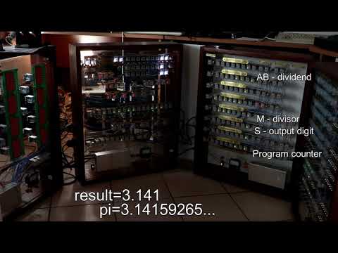
I've finished soldering ROM boards (but not yet connected all of them) and created a program for Pi approximation calculation.
It divides 355 by 113 and outputs the resulting digits into the register S.
I had to fix several bugs to make this program work:
- Two badly soldered diodes in ROM
- Two faulty relays
- Wrong ALU signal timings
 https://www.youtube.com/watch?v=bOOCfx2EN10
Speeding up the computer seems to be impossible. Sometimes the registers can't be reset during the small clock cycle. Therefore now the clock frequency remains the same.
But now with the larger memory the computer is able to execute the division subroutine:
On previous videos computer clock generator worked with 100uF capacitors. I tried to speed up the computer by replacing them with 33uF. As the calculation sequence is about 8 relays long (carry propagation in the ALU), there were some glitches at that speed. However, division subroutine works normally with 47uF capacitors. Therefore this will be the fastest operation of the my computer.
Now the ALU instructions without the writeback work normally. I fixed the control block by adding one more relay. There were other methods of fixing with more spaghetty wiring, but I prefer to make the wiring compact and have some redundancy for the possible fixing in the future.
I tried to execute a division subroutine and encountered couple of bugs:
- The "flags only" version of the ALU instructions didn't work
- There was a kind of backfeed in ALU
I've bought on ebay a dot matrix display which was previosly used in a bus.

I plan to add this to my computer to make output more verbose than just loading the values into the registers.
Now computer has ROM for 16 instructions and can execute more complex programs. Here is an Euclid's algorithm for inputs 15 and 12.
https://www.youtube.com/watch?v=RIoIWR7b1Ps
https://www.youtube.com/watch?v=P9jCTSYUaJ8
I finished the first ROM board and now my computer is capable executing the programs up to 8 instructions. The first program is calculation of the Fibonacci sequence.

New PCBs have places for diodes that block the backfeed current. I've soldered two addresses of new ROM and tested the computer with it. Reading the program now is ok, but I've found a bug in writeback to PC register by ALU.
I tried to program my 8-word ROM.
Simplest increment program seem to be working:

https://www.youtube.com/watch?v=BQ2KYB1ZIaA
But there is a problem with programs that have intersection in non-zero bits in the instructions:

I forgot to add diodes and the voltage from one selected ROM address passes to other addresses causing all of them to be selected.
Now I have to reroute PCBs and add diodes to them.
I soldered all connections in memory block. Now only 8 instructions will be available to execute.
I recently finished the third module of the computer. Now it can iterate one instruction infinitely, because there is no ROM yet. Here is an example of executing "ADD A, A, 1":
https://www.youtube.com/watch?v=l6Nn2hY0r4o
My attempts in creating plates with photo-chemical etching for control module were not successful. Therefore I ordered them in company that creates brass plates mechanically.

http://relaycomputer.blogspot.ru/
This blog documents my journey in constructing an 8-bit relay computer, from scratch, made from tons of solder, wires, lights, relays, sweat, tears, swearing and money. The design of the computer is based on the one constructed by Dr. Harry Porter at Portland State University.
HALT stops clock generator and resets all clock relays. Start button has to be pressed to continue program execution.
I've already wired processing of "MOV R, R" and "MOV Cond, R, Imm" instructions. Second one is split into "MOV", "CALL", and "JMP" subinstructions. I also had to replace two of already soldered relays because of weak contacts.
Here is the video of "MOV R, R" instructions operating:
http://www.youtube.com/watch?v=9-YLV_muugg
Today I've started PC execution loop, which is capable of continuous incrementing PC (for subsequent instructions fetching). However, there is a bug, which doesn't allow executing more than 32 instructions :) Video will come later.
Found several issues in schematics:
- There is no available contacts for making 1-tick PC selection for update (tick 5). Therefore I will use tick 4 and 5 for selecting PC to address bus for proceeding to the next instruction
- I switched contacts in trigger relays of incrementer, because there are simpler to connect the relay power pin to "inputs" and not to the outputs as on several schemes
- I will also have to add one more S4 signal duplication relay to produce forgotten S4.INC which will be passed to PC Load
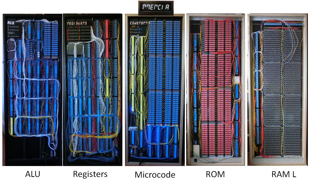
Recently I found another relay computer project - MERCIA.
MERCIA means Mijn Eenvoudige Relais Computer In Aanbouw, or My Simple Relay Computer Under Construction.
In this computer registers and instruction have 10-bit width. ALU also functions as incrementor for the program counter and is also used to do the addition for relative addressing. It is also implements fast multiplication and division with assistance of ROM subroutines.
Author has already implemented ROM and RAM blocks:
Sequencer generates 10 signals for different phases of instruction decoding and execution. It supports two speeds and single step mode, when every instruction is started manually.
http://www.youtube.com/watch?v=uoBxHk3x_44
Soldered clock generator.
http://www.youtube.com/watch?v=gtkKMYmQvT4

Started soldering of control block. It will decode instructions and pass signals to other blocks.

radiolok published his work in progress materials on relay computer: https://github.com/radiolok/RelayComputer2
Description of ALU: http://tqfp.org/radiolok/releynaya-evm-versiya-2-releynaya-logika-alu.html
Some photos https://rln.nnov.ru/index.php?ind=gallery&op=section_view&idev=14
Previously he built simpler version of a relay-based computer, described in book "NOWOCZESNE ZABAWKI" by JANUSZ WOJCIECHOWSKI: https://rln.nnov.ru/index.php?ind=reviews&op=entry_view&iden=126
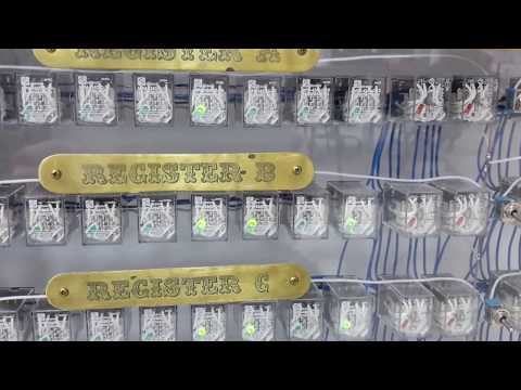
The registers module is finished.

It contains 8 of 8 bit registers. One of them is instructions counter and another one - link register. Four of registers may be used for memory access.
http://habrahabr.ru/post/258337/
Found discussion on StackExchange, which references A fistful of relays project:
Relay Calculating Engine is a machine that calculates square roots.

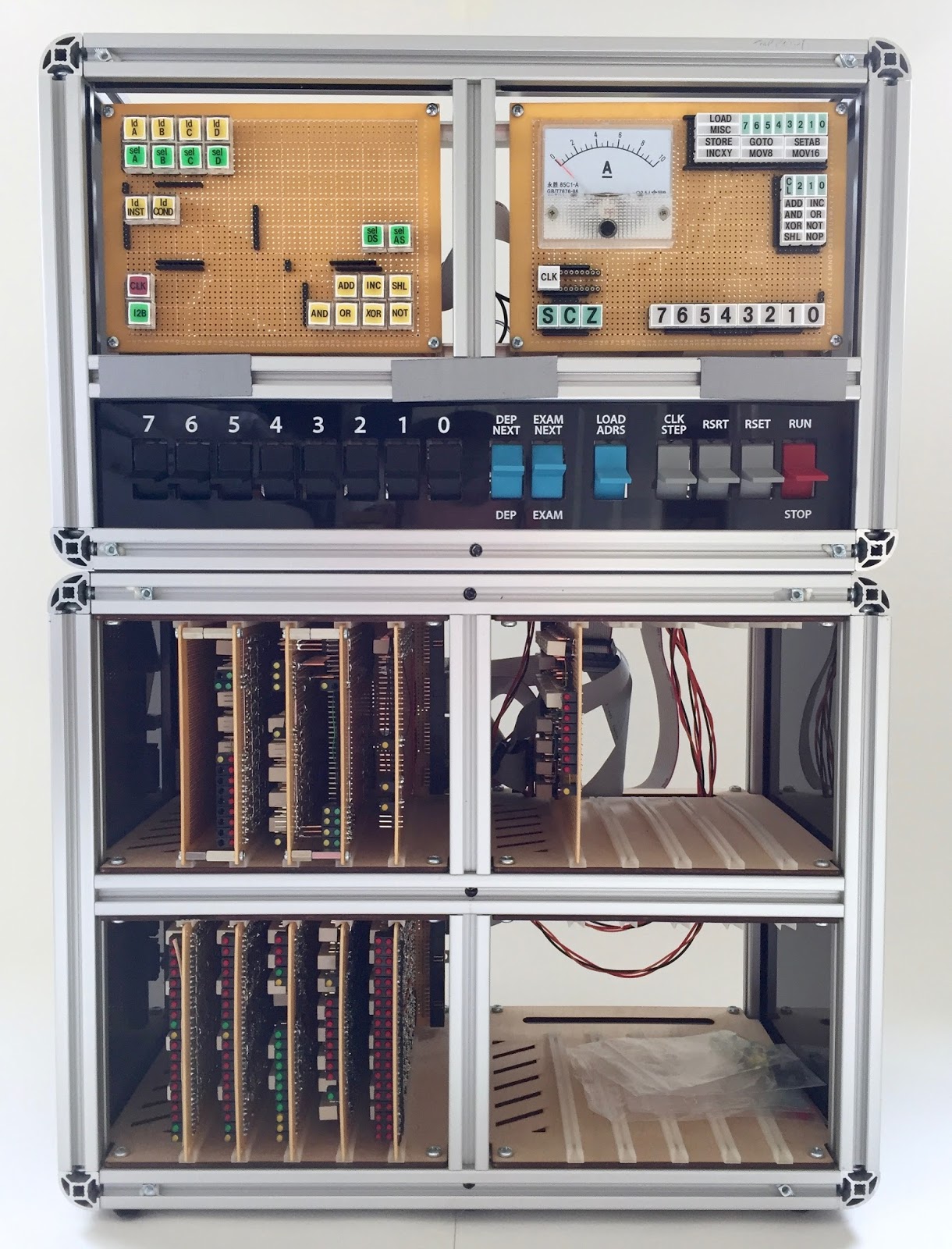
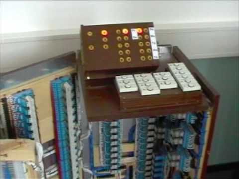
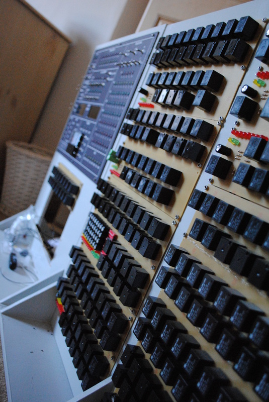
The frame of the relay computer can hold up to 30 identical relay modules, built using printed circuit boards. Each was designed to hold 16 relays for a total of 480 relays maximum. The display unit makes use of eight Russian IN-16 nixie tubes.
Computer is driven by mechanical clock pulse generator. This makes use of a motor driving a cam which presses alternately on two microswitches. Using this device I can generate regularly spaced pulses to sequence the machine through its various internal states during operation. The speed of the clock can be varied by the user so that they can watch carefully the sequence of lights corresponding to relays energizing when the machine is in operation.
http://simonwinder.com/projects/relay-calculating-engine/

MERCIA means Mijn Eenvoudige Relais Computer In Aanbouw, or My Simple Relay Computer Under Construction. It is a Dutch acronym for a project that is taking me more than a year, and the finish is not even in sight.
It is not finished yet. Project site provides documented computer design.
MERCIA in a nutshell
- 10 bit word
- 16 bytes I/O memory
- 496 bytes ROM
- 512 bytes RAM
- ±1700 relays
- 9 panels 50cm*120cm
- >50.000 parts

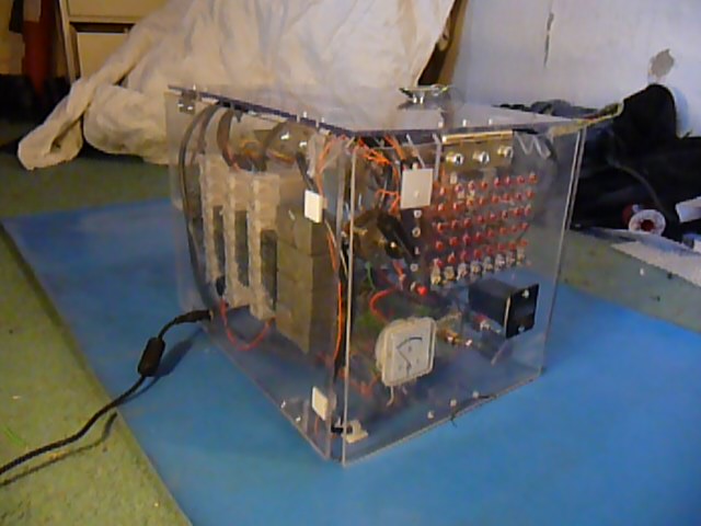
Another computer found on youtube:
https://www.youtube.com/watch?v=aDRlKpLc-9E
Built as something to keep me busy over the Summer holidays from Uni. 168 relays in total with about 25m of wire joining them all up. Requires 12V to operate and draws about 2-3 Amps peak. It is a very basic computer containing an ALU and Memory that has a data width of 4 bits.
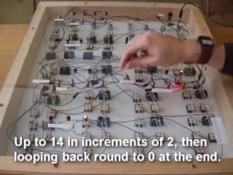
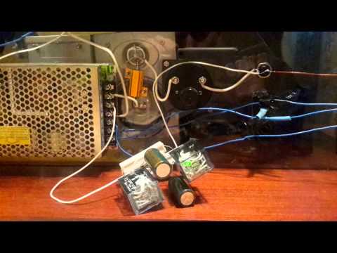
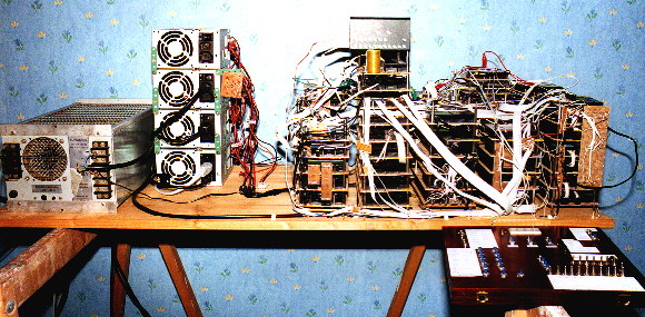
R500/7T computer was built by Christof Traber. It is built from about 500 electromechanical relays and performing about 7 instructions per second. The computer was developed and built between 2001 and Oct 2006
Dr. Christof Traber is a former professor of computer science at the Swiss Federal Institute of Technology and currently a senior engineer at SVOX AG specializing in speech synthesis technology.
The computer is driven by 24 VDC. The power supply is a conventional 230 VAC to 24 VDC transformer-rectifier-condenser unit. Actually, the unit turned out to be somewhat oversized, since it could provide 20 Amps @ 24 VDC, whereas the computer does never consume more than about 4 to 5 Amps. Most people are surprised to hear how small the power consumption of the machine is (only around 100 Watts at maximum).
https://www.youtube.com/watch?v=67jLony0mXg
Computer architecture: http://strangecalc.ch/architecture.jpg
Me and my colleagues tested all new relays. 2 of 40 has one unrealiable contact each. And they actually have white control LED. Now I can differentiate relays in control block by ofunctions and LED color.
I recently googled information about other relay computers and found work-in-progress project by Ian Gordon. He already implemented several registers and logical circuits on relays and demonstrates some calculations in his videos.
http://www.youtube.com/watch?v=BiXrzcCdPxk
I finally made plates for the registers module. The toughest part of making them was applying and developing photoresist.

I also got 40 new custom relays ($2.3 each, including shipping) from China. Every relay is supposed to have white control LED. But I haven't tested them yet.

I've corrected the clock generator. Now it makes 3 ticks per second. Full cycle consists of 2 ticks. Therefore clock frequency is 1.5Hz. I used R = 100 Ohm and C = 330 uF for delay circuit.

http://www.youtube.com/watch?v=uVY6qsk3CsQ
I've decided to shrink down PC register and address bus. For now it will be 8 bits in width. Then the computer will have opportunity to address 256 instructions. With clock rate 5Hz it will take 0.2*10*256 = 512 seconds to execute them all. This is rather slow. That's why there is no need to have larger bus. Anyway, I can always add some segment registers to switch between memory banks.
Such a simplification will lead to removing 12/16-bit commands and reworking some of the currently created schemes. I'll probably get rid of one GPR and reuse it as PC. That would also simplify everything. And I also should find something to rework LOAD/STORE instructions.
I decided not to implement INC W and MOV P, Imm12 instructions. These are almost useless because of Ph:Imm addressing for LOAD/STORE functions.
I recieved PCBs that I ordered on the factory in China. They produced 10 PCBs. I will use 8 of them to create ROM for the computer. But there is one bug in these boards - I will have to sand switches a little bit, because they do not fit in one line to each other.

I've got some components for building of the next block: switches, LEDs, switches for ROM, power supply. I also bought brass plates for making signs.
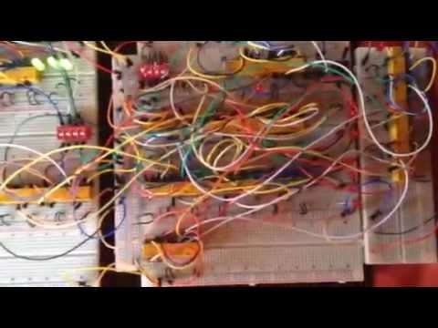
Started experimenting on clock generator. I designed a scheme which consists of 2 relays and RC circuits:

Then I bought two 100 Ohm resistors and two 1500 uF capacitors.

Soldered clock works with 2.66 seconds period:
http://www.youtube.com/watch?v=7NZI0PF3qEE
Time for energizing the capacitor and switch on the relay is about 0.2 sec (as I planned). And discharging the capacitor and switching off the relay takes 0.93-1.2 sec. Thus the left relay performs the charging-discharging cycle. It is switched on within ~1.2 sec and off within ~1.4 sec. This is almost perfect square wave.
I'll probably reduce the capacitors and make two speeds of execution (switched by "turbo" button).
Created schematics for registers that I currently soldering. All registers can be connected to both data buses. And M/L registers can be connected to address lines.


Going to rework instructions set to create the schematic of the instructions decoder.
I already changed encodings of jmp and call instructions to make them friendly for machine code programmers.
For the several last weeks I used to solder the connections within the registers module:
- Made a cable for ALU and Registers file interconnection. I will use it for testing registers connection to data bus and latching the data from there.
- Wired all connections inside the register A.
- Started to wire register LR0 (or LR1? I'll decide it later).
The next step is wiring these components altogether.

Created cabinet for registers module:

I also bought cable for connecting modules, switches for ROM block, and 0.47 Ohm resistors to insert them into +V line. This is needed to allow connecting two different power supplies to the same power line.

Last two or three weeks I spent on designing registers module. I decided to make all the registers 8 bit width. I decided to extend 4-bit upper halves of the address registers to increase number of full 8-bit registers that could be used as ALU inputs/outputs.
All registers will be able to be connected to the both data buses. M and LR registers will also include relays for connecting them to the address bus.
Now I almost made the board, cut the cabinet, and got the relays for the registers module.
I published review of ALU creation process on habrahabr.ru http://habrahabr.ru/post/220865/ (in Russian)
I also added calculation of ALU creation cost into this publication. It was at level of 21670 RUR (about $600 at today's exchange rate).
After last post in the blog I made the following modifications of ALU:
- All the brass plates were engraved, drilled, and cut.
- Plates were installed on the main board.
- Bought and installed plastic backside to the cabinet.
- Screwed two hinges for hanging cabinet on the wall.

I've got some of the plates with text engraved.
Next I will drill the holes and cut the plate apart.

I tested all ALU functions. Now it looks that everything is almost ok (except the heisenbug with subtract block). Assembled ALU is presented on the following photo:

On this photo every relay is switched on and all LEDs (except one - which shows that result is zero) are turned on.
In this mode ALU consumes 4A of power.
Temperature inside the cabinet is about 40 degrees.
Today I finished wiring of the ALU module (excluding wires to output socket). And I made several attempts to fix or replace faulty relays:
- First, I made parallel connections for two switches in result register
- Second, I replaced (twice!) the relay in the result enable circuit.
- Then I changed connection of one of the input pins of the result enable - now it is connected to the "holding" pin of the result (not to the duplicated +V as on the scheme).
- Next bug was in AND module - poor contact in one of the relays prevented evaluating 0 bit of the result of the 'and' operation.
I almost finished wiring of the ALU module. After wiring arithmetic blocks' outputs to the result register I noticed, that some of the result bits do not receive values from the adder.
Here is the adder, which computed 0xff as a result:

Result register shows that two bits in 0xff are zeroes:

The root cause of the bug was in the buggy relay - two of the contacts of the relay in the adder enable circuit did not passed the current from inputs to outputs.
Fortunately, there were 3 spare switches in the relay for the CY in the enable circuit. I just duplicated the wires from the one of the enable relays to the CY one:

Another one relay computer: <http://www.schlaefendorf.de/relaisrechner/dokumentation/index.html></http://www.schlaefendorf.de/relaisrechner/dokumentation/index.html>
This computer has extendable architecture and consists of multiple modules. It also uses semiconductor diodes for some logic operations, that is why it is not "fair" relay computer. But it's ALU is better than most of the other ones - it can execute 8 operations including SUB/SBC.

Yesterday I finally soldered two shifter modules of the ALU. Both "modules" consist of wires and enabling circuit.
First module performs RCR/SHR (shift right with/without carry) operations, and second one is for ROR (rotate right).
Suddenly noticed, that first entry in this blog is dated 27-11-2012.
Now I've almost completed ALU module and made rough design of other components of the computer.
i² (i Squared) is a fully programmable 8-bit computer built of of relays: <http://isquared.weebly.com></http://isquared.weebly.com>
It uses over 300 6v relays mounted on boards and has taken in excess of 1900 hours to design and construct. The design draws elements from several other relay computers built by Dr. Harry Porter (RC1), Jon Stanley (RC2), MCC (RC3) and Fredrik Andersson (Zusie).
According to the blog, work on this computer is still in progress.
Relay computer "trainer": <http://relaysbc.sourceforge.net></http://relaysbc.sourceforge.net> The idea behind this project is to make a low relay count, single board computer similar to the single-board trainers of the early microcomputer era which can be mass produced for a reasonable price. CPU part of this computer consists of 83 relays. Other parts are based on ICs.

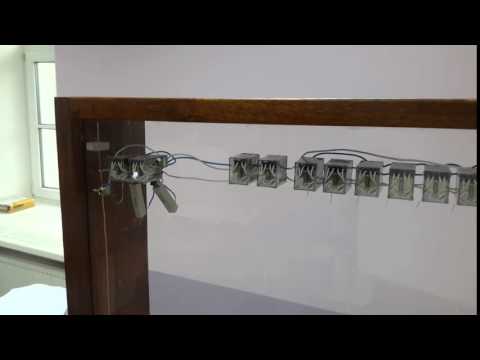
TIM relay computer: <http://www.northdownfarm.co.uk/rory/tim/tim-8.htm></http://www.northdownfarm.co.uk/rory/tim/tim-8.htm> It consists of 152 relays and controlled by punch tape and DIP switches. This computer is the "smallest Turing complete relay computers in the world by relay count (with maybe the exception of the 'DUO Premium')".
Today I finished soldering of the subtractor module.
Subtractor is one of the unique modules that is not presented in other modern relay computers (like Harry Porter's computer).

Bought four 200x200x0.3mm brass plates for making relay nameplates and M3 nuts&bolts for fastening plates on the main board.
The nuts are not made from brass, but they will be located at the hidden side of the plates and will not be visible.
After finding 3 failed relays within the subtractor module I decided to make a testing board for relays.
I checked about 30 relays using this board and all of them seem good. It seems strange because I found ~5 bad relays within set of ~50 already assembled.

I finally assembled the cabinet and inserted the ALU board into it.
The cabinet is made of merbau timber and finished with oil and wax.
The dimensions of the cabinet are the following: height - 74cm, width - 56cm, depth - 14cm.

Bought another 24V power supply and one socket for relay.
I will use them in relay testing module. And power supply block will later be reused in one of the computer modules.
Bought 100 relays SCLD-W-B-L-4PDT-C 24VDC with red LEDs.
Because of many failures of relays I plan to make testing circuit to test them before attaching and soldering.
Bought 4 planks (1.5m each) of merbau to make cabinets for ALU and registers modules.
Finished soldering and testing of ALU adder block. While replacing bad relay found another one with corrupted contacts. I probably need to make quality inspection before attaching relays to the board and soldering them.
I almost finished soldering of ALU adder module (and started using next 10m of wire) and found some strange bugs while testing it.
Some of them were caused by bad soldering (i.e. myself).
And others were really strange. First one was caused by twisted wires inside the relay. I fixed it by switching inputs of corresponding pins.
Kilian Leonhardt's relay computer: <http://www.relaiscomputer.de></http://www.relaiscomputer.de> Built in 2001, consists of 1500 relays. This site contains description of the computer in German.
Soldered 1-bit adder module. Now I can get the result of adding two 1-bit numbers and CY selected by the input switches.
After soldering found a bug in CY storage implementation - it did not pass +V to ~CY when the CY output is not selected.
Made some connections between ALU components. Also connected most of the relays to the ground and +24V lines. I used about 20m of wire to make these connections.
I also make complete wiring for ALU operation code decoder and CY storage. Now these components are almost completely tested.
Found possible backfeeds in ALU schemes. When input register is connected to the result register through the shifter block (because it consists of set of wires) or while passing result to the data bus they can latch values of each other.
This bug may be fixed by creating a "copy" of the result value and input value for shifter by using spare switches of the relays.
The following site contains description and schematic of another relay-based processor. <http://www.cs.ubc.ca/~hilpert/e/simon/index.html></http://www.cs.ubc.ca/~hilpert/e/simon/index.html>

It was created in 1950s and can be used to demonstrate principles and architecture of processors.
Here is the description taken from the site: "Simon is a Harvard architecture machine constructed from relays. The program is executed directly from paper tape. In these regards it was behind the state-of-the-art as several electronic stored-program machines were under design or construction by the late 1940s. The main data registers and ALU are 2 bits wide, data input is via either the paper tape or 5 toggle switches, output is via 5 lamps.
As an educational instrument, Simon was directed more towards the electrical implementation of logic than towards programming. As such, and as a minimal machine, programmibility is rather limited. The one saving grace may be that the program can be quite long (limited only by paper tape handling), a feature that certainly would not have been feasible in an attempt to make an inexpensive stored-program machine at the time."
Read the building log of RC-3 relay computer and understood, that I forgot about relay protection.
That is why I had to buy 100 1N4448 diodes and ammeter. I also bought 100 4.3k resistors for panel LEDs that do not have internal ones.
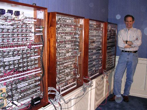
There is another documented relay computer - RC-3 built in Goodwill Computer Museum.
<http://www.computerculture.org/projects/rc3></http://www.computerculture.org/projects/rc3>

It is a clone of Harry Porter's relay computer. Here is the description of the computer from the site: "The RC-3 is an 8-bit computer with a 16-bit address bus that uses 418 electromechanical relays as logic elements. It has 421 lights and 134 switches on its front panel, and runs at the blinding speed of 6 Hz. It was designed and built by the founders of the Museum of Computer Culture during the 2010-2011 timeframe, when they were volunteers at Goodwill Computer Museum."
Several days ago I started building of ALU board.
Now I glued all requiered relays to acrylic panel and drilled the holes for switches and LEDs.
Yet more components were purchased. They will be used to create ALU module:
- 50 switches
- 50 meters of wire
- 100 red LEDs
I've purchased 100 MY4N-J relays. They are packed in 10 boxes - 10 relays per box.
I have also purchased an acrylic plate 1525х2050x6 mm. It will be used for attaching relays and other components on it. First board (for ALU) has size 540x700 mm.
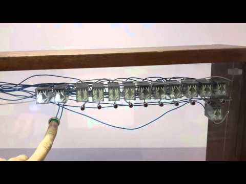
DUO 14 PREMIUM is a relay computer designed and built by Jack Eisenmann. It can execute a set of 8 commands and has 14 bits of RAM.
http://www.ostracodfiles.com/ostracod/relay.html

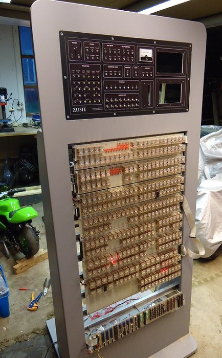
Zusie - is another implementation of relay computer. It is named after Konrad Zuse - a German engineer, inventor and computer pioneer.
More details about the computer: http://www.nablaman.com/relay/
First components for the computer:
- 25 switches
- 25 relays SCLD-W-B-L-4PDT-C 24VDC with red LEDs
- 6 relays TRY-24VDC-S-4CL with green LEDs
- 1 power supply with 24V/6.5A output
- 10 meters of 0.12mm2 cable

This projects was created to describe building of retro-style relay computer. I was inspired by the following implementations of relay computers: http://web.cecs.pdx.edu/~harry/Relay/
http://www.electronixandmore.com/projects/relaycomputertwo/index.html