A Digital Clock simulated in Logisim
Previously, I designed a digital clock that can display hours, minutes, and seconds in decimal numbers on a 7-segment LED display as “HH:MM:SS”. In this project, I added the following functionalities into the digital clock:
- The option for the clock to be changed from 24-hour mode to 12-hour mode. In 12-hour mode, use “A” on LED indicates AM and “P” indicates PM.
- An alarm feature where an LED flashing is activated at a chosen time.
- A start/stop stopwatch.
- A countdown timer.
To keep the report short, the process of designing the basic clock will not be outlined. Only the additional features described above will be explained in detail.
In order to expand from the original simple 24-hour clock, a more complex set of circuits was necessary. To keep everything simple and organised, the motherboard was divided into sections, each section fulfilling a particular purpose.
Tunnels were used to keep the circuits from being too cluttered, but the names of these tunnels got confusing quickly, so a tunnel naming scheme was also put in place.
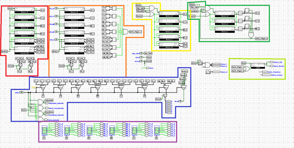
Circuit 1(Red): 2 4/12 Hour clock Circuit 2(Orange): Alarm set and trigger conditions Circuit 3(Yellow): Stopwatch Circuit 4(Green): Countdown timer Circuit 5(Lime): Alarm Buzzer/LED control Circuit 6(Blue): Mode Selection Circuit 7(Purple): Output to 7-segment displays.
The design process of these circuits is explained in detail below:
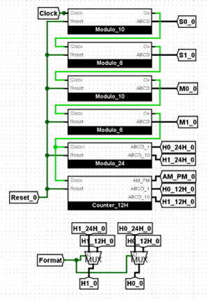
This circuit is used to calculate the current time to the user. It does this using the 24-hour clock designed in Lab 4 along with a 12-hour counter. The user then chooses whether to use 12 - hour or 24-hour time by multiplexing between the two counters.
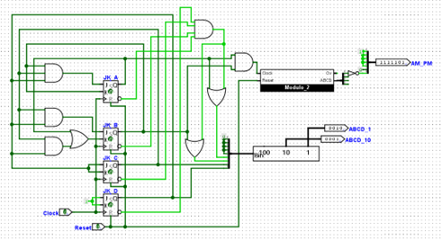
This counter was designed similarly to the other counters in Lab 4, except when the counter reaches the state “0000”, the output is set to 12. This is because in 12-hour time, “0 hours” is never reached. A binary to BCD converter is used to split the outputs into two separate digits.
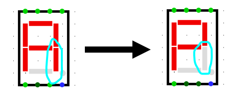
For the “A” and “P” it was noticed that the two letters only differ by one segment of the 7- segment display, so displaying the correct character was just a matter of flipping the segment on and off when the output hits “12”. A mod-2 flip flop is used to achieve this.
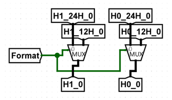
To make sure the clock displays the correct time format, the outputs from the 24-hour counter and the 12-hour counter are multiplexed, with the user selecting which format to use by inputting a “1” or a “0” into the selectors.
This circuit allows the user to select a time for the alarm to go off, and then it compares this time to the current time on the clock.
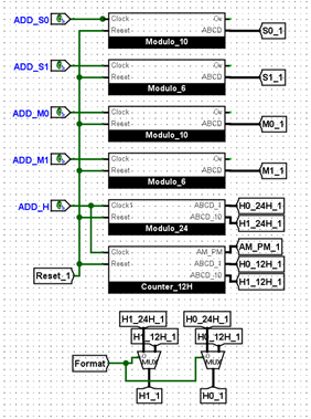
It is similar to the clock circuit with the counters and the selection between 12/24-hour time, but the main difference is that each counter has its own input, this is so that the user can press a button to advance the value of each counter individually. Once the time has been set, it is compared to the current time to determine whether the alarm needs to be triggered or not.
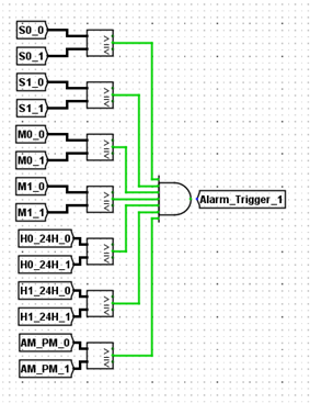
This circuit uses comparators to compare the values. Each second this comparison happens, until eventually when the two are equal, the circuit outputs a 1, triggering the alarm.
The stopwatch circuit also features the 10, 6 and 24-hour counters, but this time the 12-hour counter is omitted. This is to save on resources considering nobody uses a stopwatch in 12- hour format.
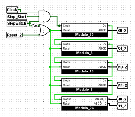
As shown in the circuit above, the clock can only advance the time of the stopwatch when the user has selected “start” in the interface and when the clock is in stopwatch mode. The stopwatch also automatically resets when the user exits stopwatch mode and stays at 0 until the user selects it again.
The time selected for the countdown timer was 2 minutes. This means I needed a mod-10, a mod-6 and a mod-2 counter to implement the countdown timer.
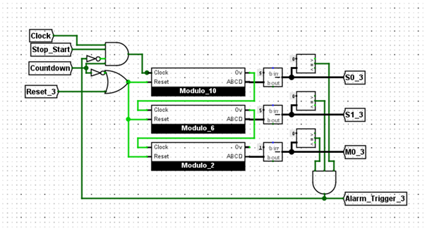
An obvious issue noticed is that the counters count up rather than down. To fix this, the value of the mod-10 counter was subtracted from 9, the mod- 6 from 5 and the mod- 2 from 1. This results in the counter counting backwards rather than forwards, but gives rise to the issue that the counter starts counting from 1:59 rather than 2:00. A solution for this would be to re- design three counters that count backwards rather than forwards, but to save on time the implementation was left as-is.
The outputs from the three counters are compared to “0”, so when the counter reaches 0 it triggers the alarm and will continue until the user restarts the timer or changes the mode. Like the stopwatch, the countdown only works when in countdown mode; it’s automatically reset when the user exits this mode.
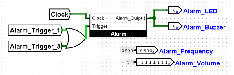
This circuit was designed so that both the countdown timer and the user-set alarm could both trigger the LED and buzzer.
The subcircuit “Alarm” is designed so that when it reads a “1” from the trigger port for one clock cycle, the output clocks on and off for the next 30 seconds. In order to achieve this, a mod-3 and mod-10 counter were used:
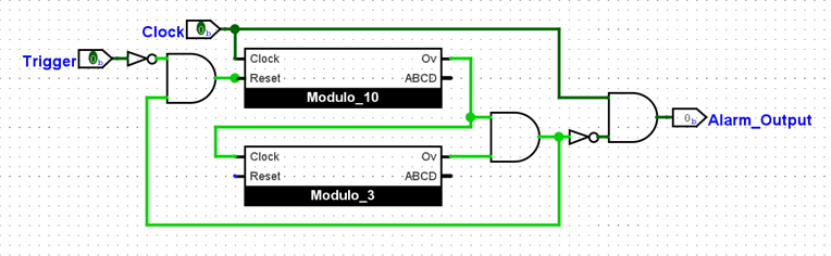
This circuit is designed so that the output is only affected by the clock when the trigger has been used, resetting the counters to “00” and therefore turning on the second terminal of the AND gate at the right. When both the mod-10 and mod-3 counter overflows, this means 30 seconds have passed and the second terminal of the AND gate turns off, cutting off the clock from the output.
In the Alarm circuit are also constants for the alarm frequency and the alarm volume. This is used for the buzzer.
Considering all the modes of the clock will be sharing the same display, using multiplexers to select which mode to display made the most sense to me. There are 4 modes the clock uses, so two-bit selection multiplexers are the best solution to swap between modes. Each mode is given a number- “00” for clock mode, “01” for alarm set mode “10” for the stopwatch and “11” for the countdown timer.
Each 7 - segment display is has four modes, (except for the hours and minutes, these are not used for the countdown timer so they only have three.) and the user changes the mode of each of them by changing the value of the “Slider” (this will be explained later.)
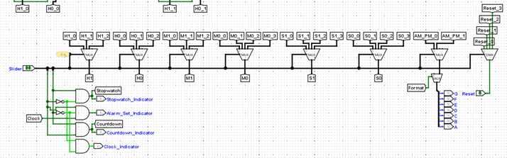
It’s also shown on the left that the reset button is multiplexed as well, this is to prevent the reset from effecting any modes other than the one it is intended for, e.g. resetting the stopwatch doesn’t reset the clock and vice-versa.
Below the multiplexers are the indicator LED’s, these light up when a mode is selected to make it completely clear to the user which mode the clock is in. The alarm set LED is connected to the clock so that it blinks when the user selects this mode. This was chosen to make it clear that the clock should not be left in this mode for too long.
The AM-PM multiplexer feeds into a second Format multiplexer. This means that when the user selects 24 hour mode, the “A” and “P” don’t show up, regardless of whether the clock or alarm-set mode is being used.
This part of the motherboard simply converts the outputs from the multiplexers (Binary coded Decimal) into a signal usable by the display.
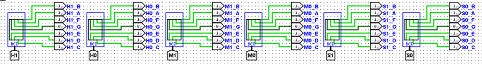
This uses BCD to 7-Segment display converters. Once this conversion has happened the signals are output to the displays on the main circuit for the user to view.
As mentioned above, tunnels were used liberally to keep the motherboard from becoming too cluttered, but they quickly became hard to manage, so a naming scheme was put in place:

Red: Time unit, (hours, minutes seconds) Green: Digit (0 for 1 st digit, 1for 2nd digit) Blue: time format (Specifically for hours) Yellow: Circuit number (As described earlier)
The final (and possibly most important) step in designing the clock was the user interface. I wanted to make something that was easy to use and intuitive, so I chose to use a slider to select the mode of the clock, rather than have a collection of buttons that could be confusing to keep track of.
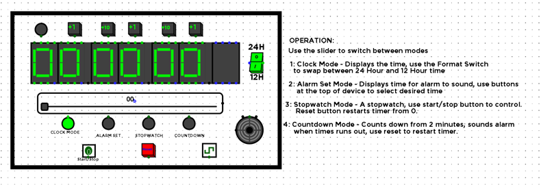
- The buttons at the top are used to set the alarm time, each button increases the digit below it by one, adding either 1 or 10 (minutes, hours or seconds) on to the total time.
- It is easy to see which format the clock is in with the labels on the format switch.
- The reset button is a red colour which stands out from the rest of the clock.
The goal of this project was to add the specified features on to the digital clock design, these were:
The option for the clock to be changed from 24-hour mode to 12-hour mode. In 12- hour mode, use “A” on LED indicates AM and “P” indicates PM. An alarm feature where an LED flashing is activated at a chosen time. A start/stop stopwatch. A countdown timer. I successfully implemented these features, but there are still a few issues that could be fixed to improve the design even further:
-
Occasionally, when the reset button is hit, the clock resets to “11:11:10”, this seemingly happens at random, but is not very common. When the button is pressed again, it resets properly to “00:00:00”. This could be a bug with the Logisim engine, but I suspect this has to do with how the counters were designed; resetting the counters to 0 triggers the overflow for 1 clock cycle. A potential fix for this would be to change the overflow conditions so that overflow is only triggered when the proper state before it was also reached.
-
The countdown timer can only count down from 2 minutes, this leaves no room for the user to set longer or shorter timers. This could be fixed by using the same “time set” system of buttons the alarm uses and then counting down from that set time.
-
The alarms system does not have an off button, so if the alarm is triggered accidentally, it is unable to be turned off for the full 30 seconds. I could fix this by changing the alarm circuit and adding an extra port for an off button that cuts off the output from the clock circuit.
I believe that despite the small bugs, the finished version is a successful recreation of a digital clock, with the features described in the brief implemented in an easy to use and intuitive manner.
From this project I learned that high-level logic circuit design can actually be very simple if the problem is broken down into smaller pieces; the hardest part is being efficient with resources, that is, knowing when a new circuit needs to be added rather than reusing something you’ve already implemented.