An external programming adapter for Silicon Labs BGM111 modules.
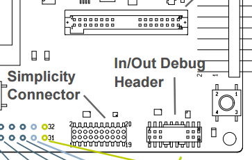
Pinouts for the external programming headers on the BGM111 WSTK (Wireless Starter Kit) can be found in UG122.
UG122: Blue Gecko Wireless Starter Kit with BGM111 Module
The minimum pins required to program a BGM111 module are:
| Signal | BGM111 Pin (PAD) | WSTK Pin |
|---|---|---|
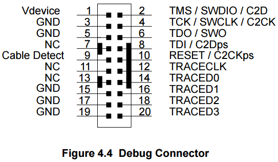
| Reset | 30 | Debug 10 |
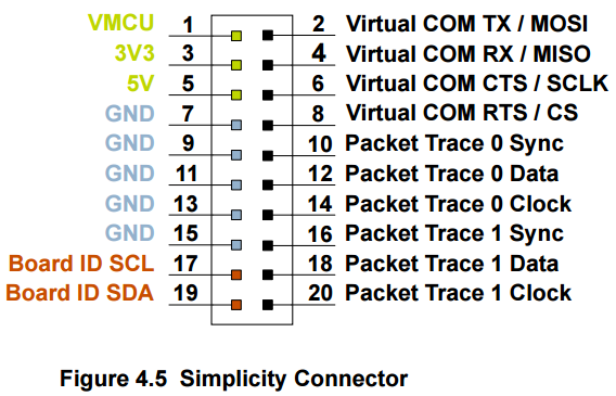
| +3.3V | 29 | Debug 1 & Simplicity 1 |
| GND | 1,12,20,31 | Debug 3,5,15,17,19 & Simplicity 7,9,11,13,15 |
| SWCLK | 21 (PF0) | Debug 4 |
| SWDIO | 22 (PF1) | Debug 2 |
(NOTE: It is important to note that Vdevice on the Debug connector is a reference voltage for the programmer and is insufficient to power a target BGM111. Power must be sourced from the VMCU pin of the Simplicity connector or from an external source.)
Often referred to in documentation as eACommander (because of its executable name eACommander.exe), this tool is used to program the flash on a BGM111 target.
eACommander is included as part of the BGM SDK.
The latest version can be found here.
Depending upon where you have installed the BGM SDK, the eACommander folder can be found relative to the install path.

(NOTE: Your WSTK should be connected to a host computer and your BGM111 target should be connected to the WSTK prior to starting eACommander.)
The eACommander executable:
If your WSTK is properly connected to and detected by your host computer, eACommander should display the serial number of the on-board SEGGER J-Link debugger at the top of the screen:

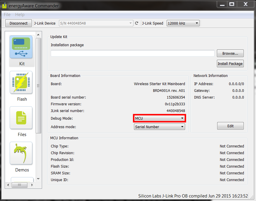
Press the "Connect" button. This should result in the "Board Information" box automatically populating with the information of the attached WSTK board:
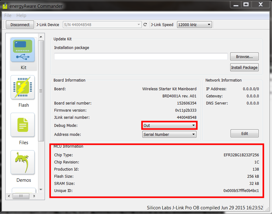
Change the "Debug Mode:" drop-down menu selection to "Out".
This should result in the "MCU Information" box automatically populating with the information of the attached BGM111 target device:
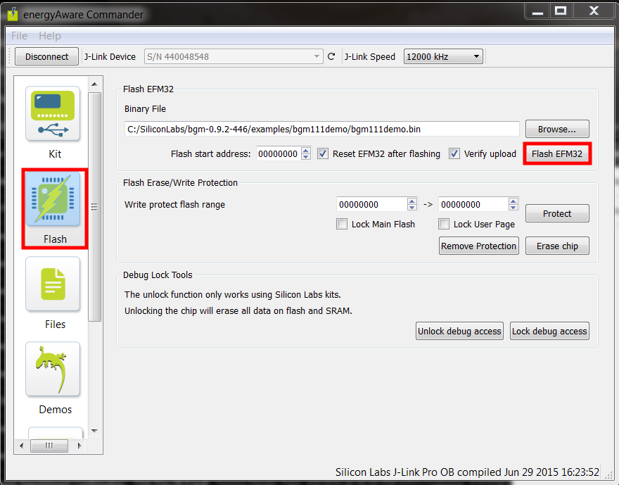
Select the "Flash" menu item from the left scroll bar.
Select the binary file you wish to flash with the "Browse..." button in the "Flash EFM32" box.
Press the "Flash EFM32" button.
For unknown reasons, it may occasionally take a few tries to get a target device to program successfully.
If you encounter errors:
- Ensure that the power switch on the WSTK is in "AEM" mode
- Ensure that your target board is not consuming too much power
- The target board is powered through the WSTK's onboard LDO TI LP3878-ADJ (rated at 800mA) and drawing too much power may result in a brownout
- Retry pressing the "Flash EFM32" button
- "Disconnect" and "Connect" the J-Link debugger using the button in the top-left of eACommander
- Disconnect everything and repeat the above steps
This adapter is designed to work with Tag-Connect.
Specifically, TC2030-MCP-NL (because of its small footprint) or TC2030-MCP.
Tag-Connect footprints for most common CAD packages can be found here.
A retaining clip for the TC2030-MCP-NL can be found here.
You may order a set of three (3) of the PCBs for these programming boards from OSH Park for ~$5.45:
Alternatively, feel free to use the included Gerber files to have them manufactured elsewhere.
The Bill of Materials for this board consists of only two components.
| Designator: | Quantity: | Cost: | Part Number: | Note: | Footprint: | Link: |
|---|---|---|---|---|---|---|
| J1 | 1 | $0.4400 | 54601-906WPLF | RJ12 Jack | http://portal.fciconnect.com/Comergent//fci/drawing/c-bmj-0082.pdf | http://www.newark.com/fci/54601-906wplf/cat3-rj12-modular-jack-6-position/dp/51M7960?ost=54601-906WPLF&selectedCategoryId=&categoryName=All+Categories&categoryNameResp=All+Categories |
| P1, P2 | 2 | $3.2400 | FLE-110-01-G-DV | 2x20 Female Header, 1.27mm Pitch | http://www.farnell.com/cad/320900.pdf | http://www.newark.com/samtec/fle-110-01-g-dv/board-board-connector-socket-20/dp/11P4413 |

(NOTE: The pinouts on the Debug and Simplicity connectors appear to be flipped horizontally in the schematic as they are mounted on the bottom of the adapter board.)


(NOTE: The adapter may need to be seated slightly askew to properly mate with the headers on the WSTK. This is due to the uneven height of the Debug and Simplicity connectors on the WSTK.)
