CAN Bus
CAN = Controller Area Network
This is not directly supported by RasPi expansion header. Instead, a HAT or similar adapter board is necessary providing a CAN Bus controller and transceiver (physical layer). Tests were done using a DualCanberry 2.1.2..
- SK Pang's PiCAN2 CAN-Bus Board for Raspberry Pi 2/3
- Industrialberry's Canberry Boards
Either board is using the MCP2515 + MCP2551 chipset. Docs including schematics are available form the board vendor's website.
The Linux CAN bus software API is called SocketCAN, a network like interface using sockets and networking commands.
The RasPi must be told that SPI+CAN peripherals are attached. There is no way for the Raspi to detect this automatically. Add two lines loading appropriate device tree overlay, see also your board docs:
dtoverlay=mcp2515-can0,oscillator=16000000,interrupt=22
dtoverlay=spi-bcm2835-overlay
After reboot, there should be a line
[ 3.626187] mcp251x spi0.0 can0: MCP2515 successfully initialized.
in the kernel log (check with dmesg | grep can)
After reboot, you may activate the can0 interface manually:
root@raspberrypi3:~# ip link set can0 type can bitrate 1000000
root@raspberrypi3:~# ip link set up can0
Check the kernel log again and you will find two additional lines:
[  263.295942] can: controller area network core (rev 20120528 abi 9)
[  263.313834] can: raw protocol (rev 20120528)
root@raspberrypi3:~# ip link set down can0Edit /etc/network/interfaces. add the following lines, save and reboot:
auto can0
iface can0 inet manual
        pre-up /sbin/ip link set $IFACE type can bitrate 1000000
        up /sbin/ifconfig $IFACE up
        down /sbin/ifconfig $IFACE down
After the next reboot, can0 should be up and running (check with ifconfig):
can0      Link encap:UNSPEC  HWaddr 00-00-00-00-00-00-00-00-00-00-00-00-00-00-00-00
          UP RUNNING NOARP  MTU:16  Metric:1
          RX packets:0 errors:0 dropped:0 overruns:0 frame:0
          TX packets:0 errors:0 dropped:0 overruns:0 carrier:0
          collisions:0 txqueuelen:10
          RX bytes:0 (0.0 B)  TX bytes:0 (0.0 B)
...
A Analog Discovery 100MS/s USB Oscilloscope & Logic Analyzer was used for measurement. Place a 120 Ohm bus termination resistor between CANL and CANH. Measure voltages between CANL (channel 1, yellow) and GND respectively CANH (channel 2, blue) and GND. Set a one-shot trigger for a raising edge on CANH, see picture below). A X resolution of 5µs/div, and Y resolution of 1V/div was used.
Send a CAN bus message:
root@raspberrypi3:~# cansend can0 014#01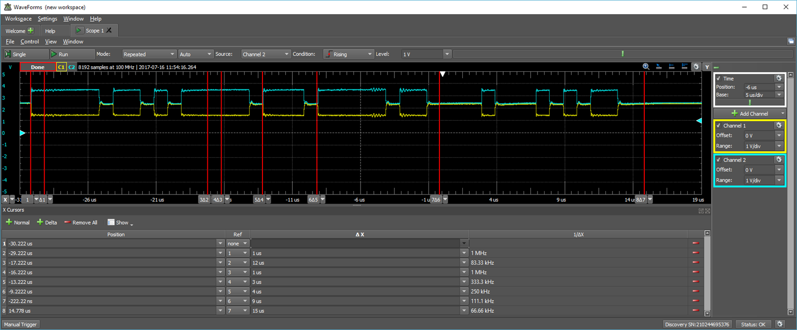
Note: since there is no receiver for the message attached to the bus, the message is not acknowledged and the sender repeats sending the same message over and over again. To stop this, bring can0 down and up again, after sending the message.
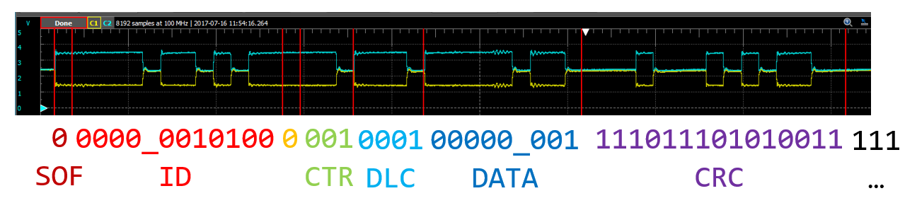
The underscore ("_") designates stuff bits which have to be inserted after 5 consecutive bits with the same value. Stuff bits do not carry information and have to be discarded when decoding the message.
One can decode the message ID: 014, the (payload) data length DLC: 1 and the one byte payload itself: 0x01 and more.