Node
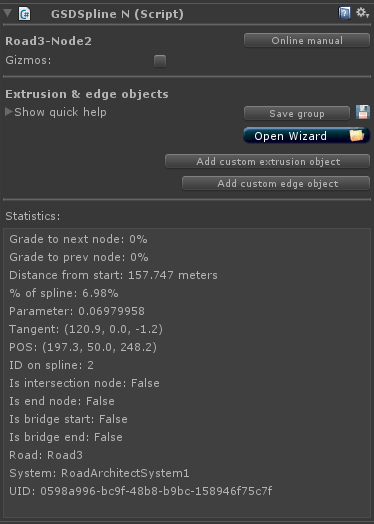
- Gizmos Enable or disable most gizmos for this node. Disable mesh collider gizmos via the unity menu if necessary or desired.
- Save group allows the saving of a group of items for easy replication.
- Open wizard opens the creation wizard, allowing the user to easily create prefabricated bridges, systems, railing, signs and more.
- Add custom extrusion object adds a custom extrusion object to the node.
- Add custom edge object adds a custom edge object to the node.
- Statistics displays general statistics about the node.
-
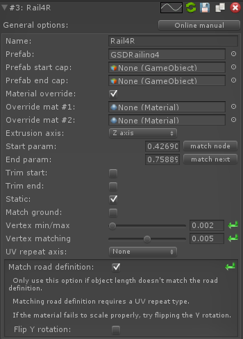
Name The name of the extrusion object.
-
Prefab The prefab or FBX file to repeat along the spline.
-
Prefab start cap The start cap of the prefab. Please watch all extrusion object tutorial videos for more comprehensive information.
-
Prefab end cap The end cap of the prefab. Please watch all extrusion object tutorial videos for more comprehensive information.
-
Material override If enabled, instead of using the prefab's material, the extrusion object will use the override materials listed below.
-
Override mat #1 The first override material.
-
Override mat #2 The second override material.
-
Extrusion axis The axis in which the prefab is extruded, either the X-axis or Z-axis. Please watch all extrusion object tutorial videos for more comprehensive information.
-
Start param The start parameter of the extrusion object. Corresponds to the parameter of the spline.
-
End param The end parameter of the extrusion object. Corresponds to the parameter of the spline.
-
Trim start Trims the start of the extrusion object by one length of the extrusion object.
-
Trim end Trims the end of the extrusion object by one length of the extrusion object.
-
Static Marks the created object as static.
-
Match ground If enabled, makes the extrusion object hug the terrain, road or whichever object is directly beneath the extrusion object.
-
Vertex min/max This value is the threshold in which the start and end vertices are detected on the base prefab. For example, a value of 0.002f (or 2mm) will retrieve the outermost values along the extrusion axis and then reflect inward 2mm and mark all detected vertices and start and end vertices. Please watch all extrusion object tutorial videos for more comprehensive information.
-
Vertex matching This value is the allowable error rate when attempting to match mirrored vertices. For example, a value of 0.005f (or 5mm) will allow an error of 5mm in determining matching vertices. Please watch all extrusion object tutorial videos for more comprehensive information.
-
UV repeat axis Determines which axis the UV will repeat. This option is typically used in conjunction with the match road definition option.
-
Match road definition If enabled, attempts to match the length of the object to the road definition value. This option should only be used for objects without any middle vertices.
-
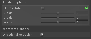
Flip Y rotation Flips the Y rotation of the extrusion object by 180 degrees.
-
 = Indicates this is an extrusion object.
 -
 = Duplicates the extrusion object.
 -
 = Manually updates the object.
 -
 = Deletes the extrusion object.
 -
 = Allows saving of this extrusion object via a save dialog. This saved item can then be loaded onto other nodes via the creation wizard.
 -
 = Reset to default value.
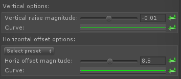
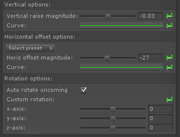
- Vertical raise magnitude The magnitude of vertical rise given to the extrusion object. This magnitude is interpolated along the extrusion length as the value of the Vertical Curve. Please watch all extrusion object tutorial videos for more comprehensive information.
- Horizontal offset magnitude The magnitude of horizontal offset given to the extrusion object. This magnitude is interpolated along the extrusion length as the value of the Horizontal Curve. Please watch all extrusion object tutorial videos for more comprehensive information.
-
= Reset to default value.
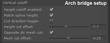
- Vertical cutoff Vertical cutoff options allow for suspension bridge cables and arch bridges. The vertical cutoff options are not utilized for any other purpose.
- Match spline height Attempts to match the spline's height. If the cut direction toggle is enabled, the match spline height is applied to the base. If the cut direction toggle is disabled, the match spline height is applied to the top.
- Cut direction toggle Toggles the direction of the cut, either top or bottom. For example, a suspension bridge will need to be "cut" at the top and an arch bridge will need to be "cut" in the opposite direction.
- Height cut offset Offsets the base cut level. For example, this setting will affect a suspension bridge cable's bottom area and will affect an arch bridge's top area.
- Opposite dir cut If enabled, flips the mesh before cutting.
- Mesh cut offset The vertical height cut offset which is applied to the cut ends of the mesh. Allows fine tuning of the cuts. For example, sometimes your suspension bridge cables may stick through the top of the main cable and might need fine tuned.
-
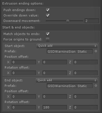
Push endings down If enables, pushes the endings of the extrusion object down into the ground. Creates realistic effects with KRails, WBeams and other types of railing.
- Override down value If enabled, overrides the down value with the below option.
- Downward movement The override down value.
- Match objects to ends If enabled, attempts to place the start/end extra objects with the proper end placement.
- Force origins to ground If enabled, attempts to force the extra objects to hug the ground.
-
Start object Allows placement of an extra object at the start of the extrusion. Excellent for sand barrels, warning signs or attenuators.
- Start quick select A drop-down which features quick selection of extra objects.
- Start prefab The prefab used to generate the start object.
- Start position offset Adds a positional offset to the start object.
- Start rotation offset Adds a rotational offset to the start object.
-
End object Allows placement of an extra object at the end of the extrusion. Excellent for sand barrels, warning signs or attenuators.
- End quick select A drop-down which features quick selection of extra objects.
- End prefab The prefab used to generate the end object.
- End position offset Adds a positional offset to the end object.
- End rotation offset Adds a rotational offset to the end object.
-
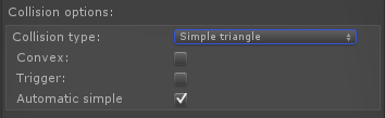
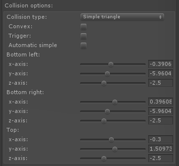
Collision type drop-down Select the collision type.
- None Disables all collision on this extrusion object.
- Simple mesh triangle Uses a dynamically created simple mesh triangle as the collider for the extrusion object.
- Simple mesh trapezoid Uses a dynamically created simple mesh trapezoid as the collider for the extrusion object.
- Base Mesh collision Uses the extrusion object's mesh filter as the collider for the extrusion object.
- Box collision When using the straight line option for bridges, a box collider can be used as the collider.
- Convex Corresponds to the convex option on mesh colliders.
-
Trigger Corresponds to the trigger option on mesh colliders.
- Automatic simple
- Enabled If simple triangle or trapezoid is selected and this option is enabled, the mesh collider dimensions will automatically created.
- Disabled If disabled and simple triangle or trapezoid is selected, allows the user to customize the dimensions of the dynamically created mesh collider.
- Custom rotation Rotates the base prefab before extrusion takes place.
- Directional extrusion A deprecated option, extrudes the objects by different methods.
-
= Reset to default value.
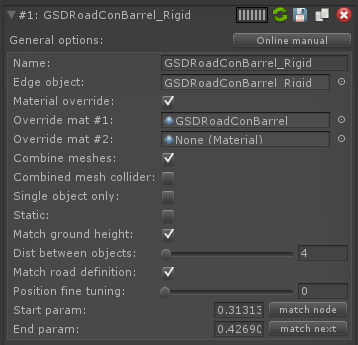
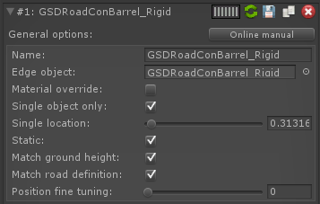
- Name The name of the edge object instance.
- Edge object The prefab or FBX file representing this edge object.
-
Material override If enabled, instead of using the prefab's material, the edge object will use the override materials listed below.
- Override mat #1 The first override material.
- Override mat #2 The second override material.
- Combine meshes If enabled, combines all edge objects into one mesh.
- Combined mesh collider If enabled, uses a mesh collider for the combined mesh.
- Single object only If enabled, only creates a single edge object.
- Single location If a single edge object, then use this value to place the single edge object along the spline.
- Static Marks the created edge object(s) as static.
- Match ground height If enabled, the edge object(s) hug the ground.
- Dist between objects The distance between each edge object.
- Match road definition Attempts to match the road definition in terms of distance between objects. For example, if the road definition is 5 meters, the distance between objects will be 5 meters while attempting to start at a road definition segment.
- Position fine tuning Fine tunes the start distance on a scale of 0 meters to the road definition meters.
- Start param The start location of the edge objects.
- End param The end location of the edge objects.
-
 = Indicates this is an edge object.
 -
= Duplicates the edge object.
-
= Manually updates the object.
-
= Deletes the edge object.
-
= Allows saving of this edge object via a save dialog. This saved item can then be loaded onto other nodes via the creation wizard.
-
= Reset to default value.
- Vertical raise magnitude The magnitude of vertical rise given to the edge object. This magnitude is interpolated along the edge object repeat length as the value of the Vertical Curve. Please watch all edge object tutorial videos for more comprehensive information.
- Select horizontal preset Offers horizontal offset magnitude presets such as road edges and shoulder edges for easy placement of railing and signs.
- Horizontal offset magnitude The magnitude of horizontal offset given to the edge object. This magnitude is interpolated along the edge object repeat length as the value of the Horizontal Curve. Please watch all edge object tutorial videos for more comprehensive information.
- Auto-rotate incoming Automatically rotates the object 180 degrees around the y-axis if placed on the left side of the road (negative horizontal offset magnitude).
- Custom rotation Rotates the base prefab before edge object repetition takes place.
-
= Reset to default value.