- Abstract
- Reference Circuit Diagram
- Reference Waveform
- Circuit Details
- Truth Table
- Software Used
- Circuit Diagram in eSim
- Verilog Code
- Makerchip
- Makerchip Plots
- Netlists
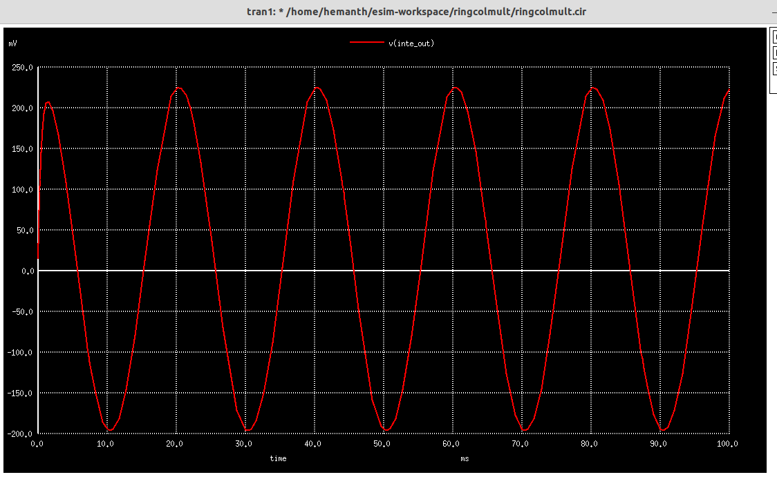
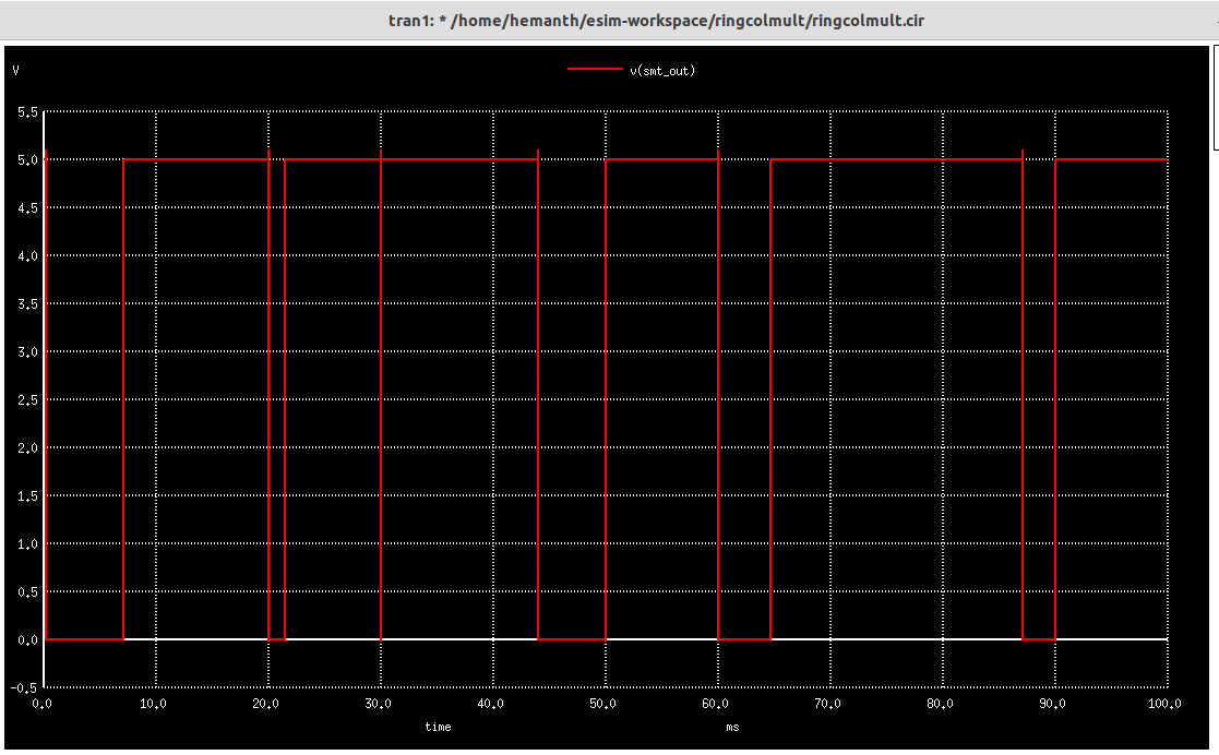
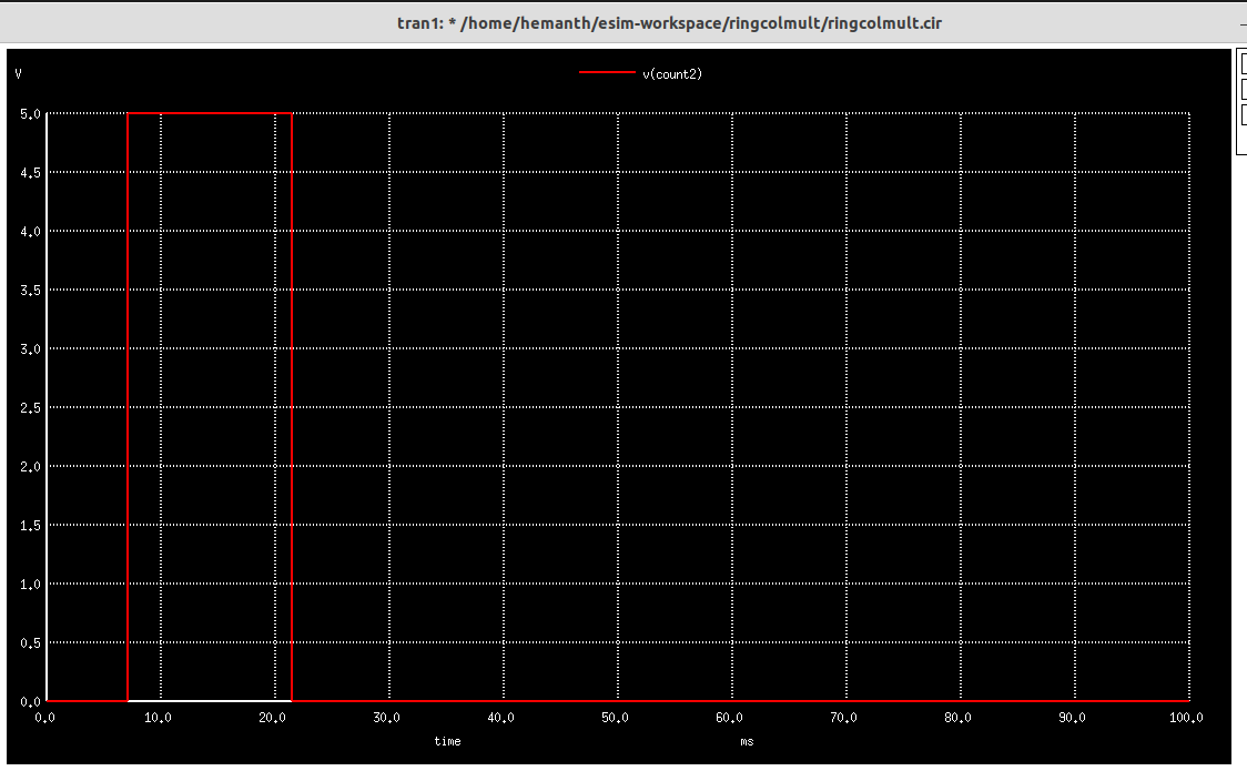
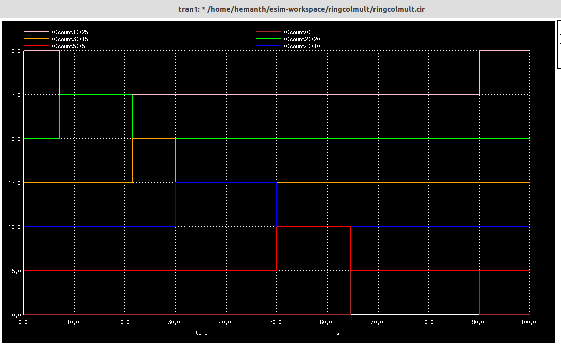
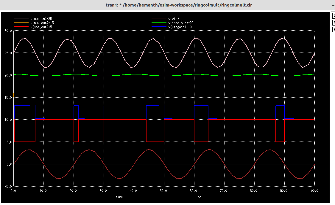
- NgSpice Plots
- GAW Plots
- Steps to run generate NgVeri Model
- Steps to run this project
- Acknowlegdements
- References
Table of contents generated with markdown-toc
An integrator is an op amp circuit, whose output is proportional to the integral of input signal. An integrator is basically an inverting amplifier where we replace feedback resistor with a capacitor of suitable value. A multiplexer (MUX) is a device allowing one or more low-speed analog or digital input signals to be selected, combined and transmitted at a higher speed on a single shared medium or within a single shared device.A Colpitts oscillator looks just like the Hartley oscillator but the inductors and capacitors are replaced with each other in the tank circuit.Schmitt trigger devices are typically used in signal conditioning applications to remove noise from signals used in digital circuits, particularly mechanical contact bounce in switches.A ring counter is a type of counter composed of flip-flops connected into a shift register, with the output of the last flip-flop fed to the input of the first, making a "circular" or "ring" structure.
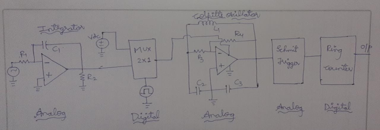
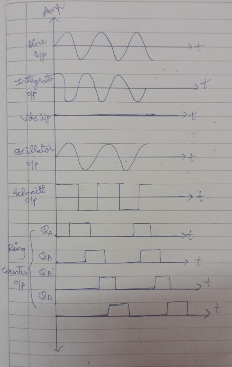
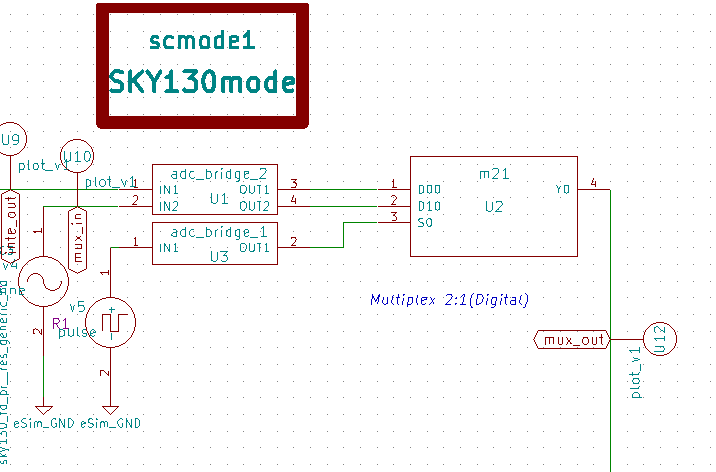
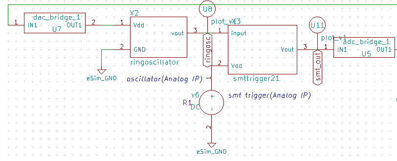
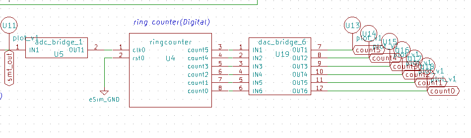
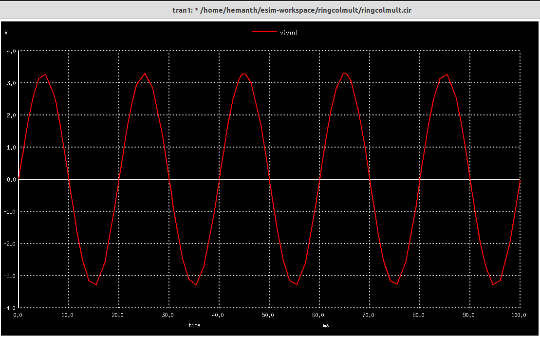
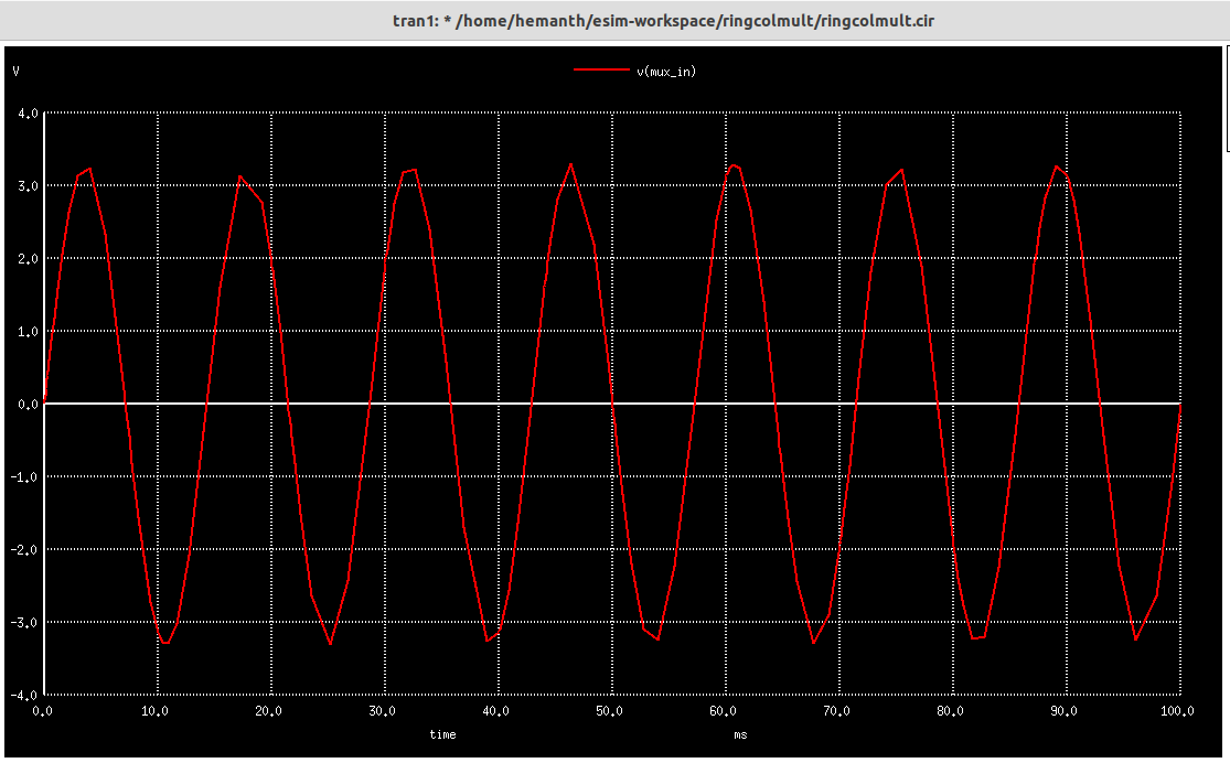
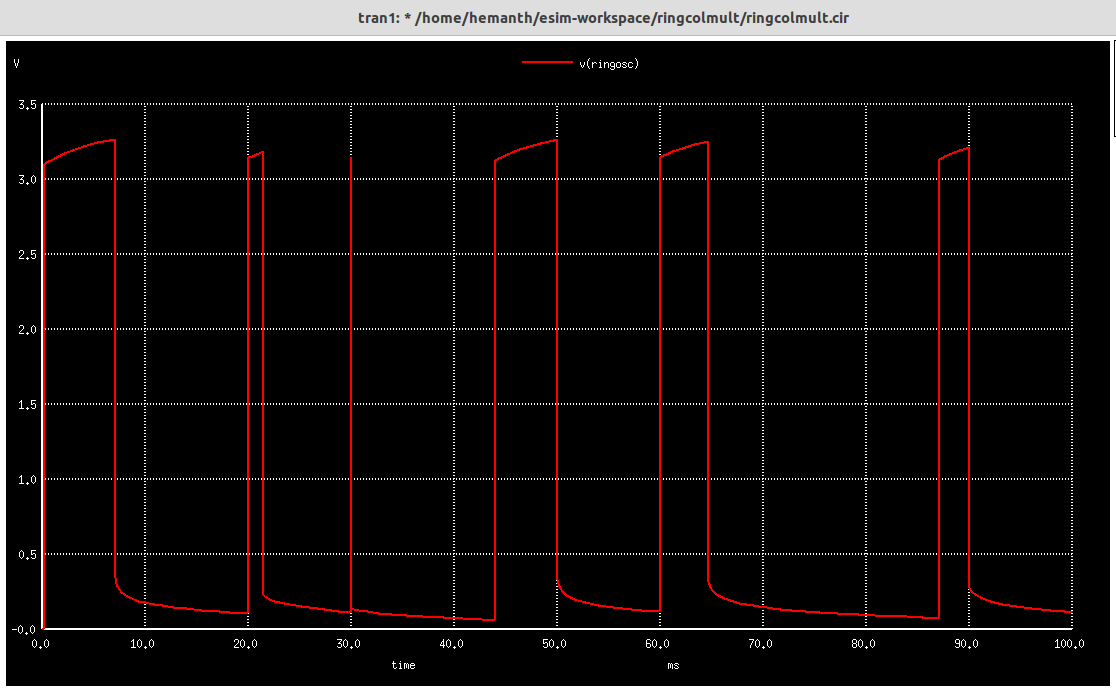
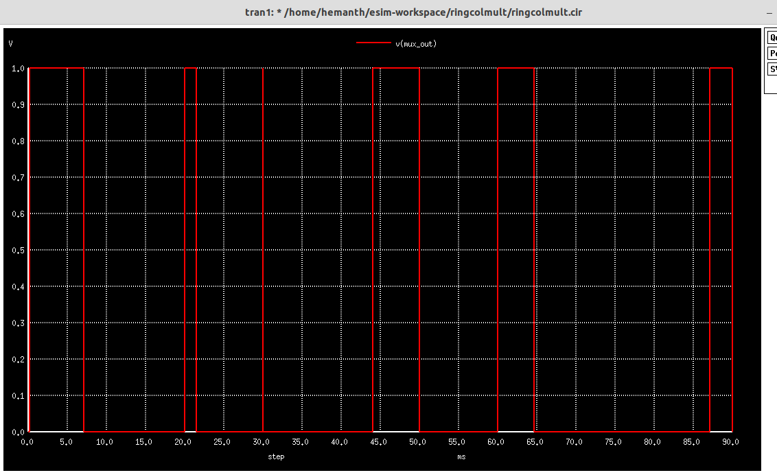
The circuit contains the integration of op amp based integrator, 2×1 multiplexer, Colpitts oscillator, schmitt trigger and ring counter. The connections are shown in the Figure1. The expected waveforms are shown in Figure 2. The implementation focuses on the input selected through the multiplexer. It is basically focusing on mixed signal integration. When the mux select line is 0, it selects vdc output. When is 1, it will select the integrated output from the integrator. Next stage, the output is given to the oscillator to produce the sine wave. The sine wave is given as input to schmitt trigger to produce pulse output. The pulse output is used to produce the ring counter output.
It is an Open Source EDA developed by FOSSEE, IIT Bombay. It is used for electronic circuit simulation. It is made by the combination of two software namely NgSpice and KiCAD.
For more details refer:
https://esim.fossee.in/home
It is an Open Source Software for Spice Simulations. For more details refer:
http://ngspice.sourceforge.net/docs.html
It is an Online Web Browser IDE for Verilog/System-verilog/TL-Verilog Simulation. Refer
https://www.makerchip.com/
It is a tool which converts Verilog code to C++ objects. Refer: https://www.veripool.org/verilator/
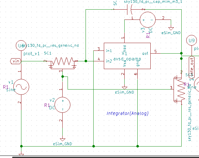
The following is the schematic in eSim:
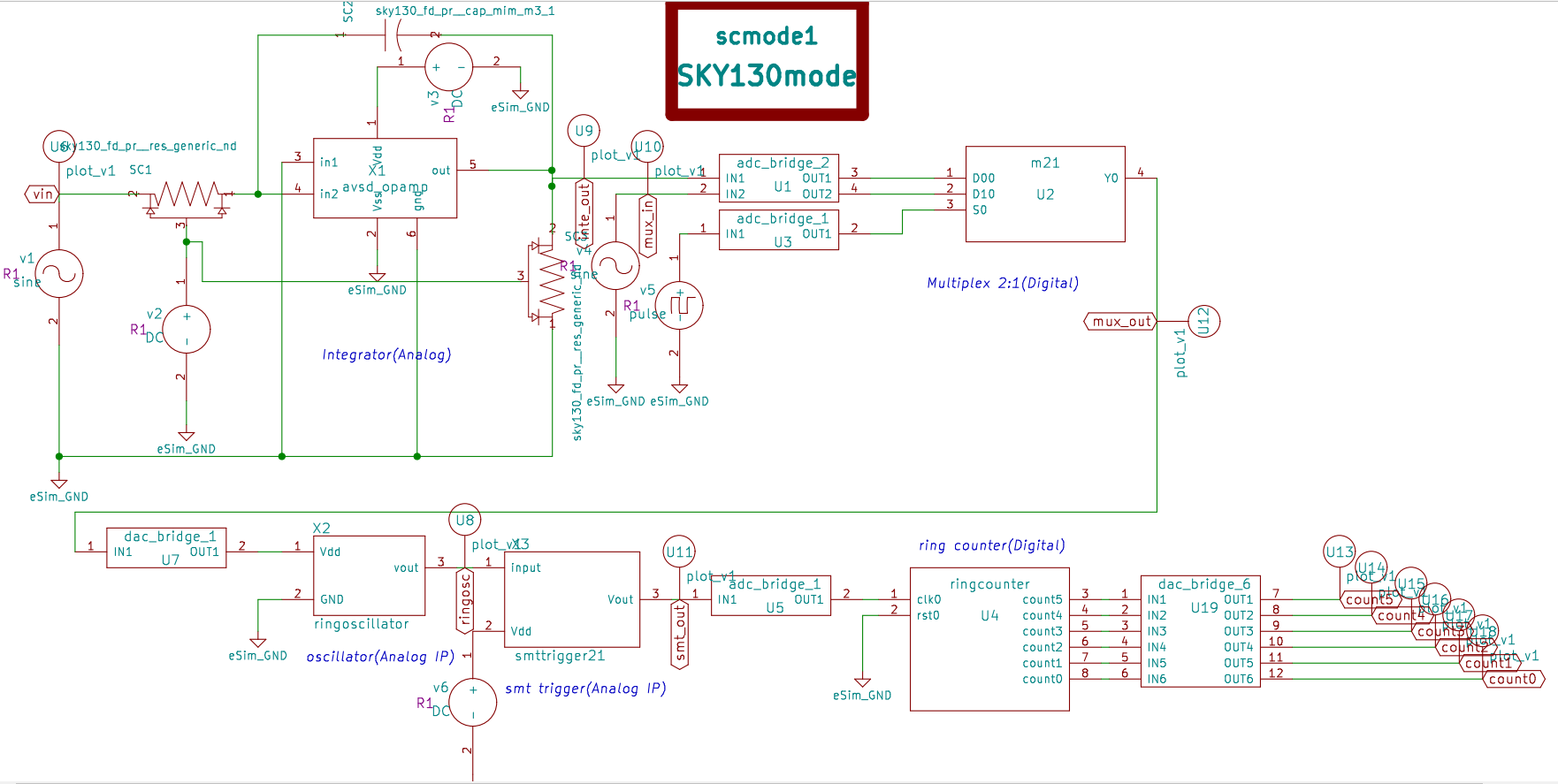
Integrator circuit:
Multiplexer 2:1
Oscillator and smttrigger:
Ring counter:


\TLV_version 1d: tl-x.org
\SV
/* verilator lint_off UNUSED*/  /* verilator lint_off DECLFILENAME*/  /* verilator lint_off BLKSEQ*/  /* verilator lint_off WIDTH*/  /* verilator lint_off SELRANGE*/  /* verilator lint_off PINCONNECTEMPTY*/  /* verilator lint_off DEFPARAM*/  /* verilator lint_off IMPLICIT*/  /* verilator lint_off COMBDLY*/  /* verilator lint_off SYNCASYNCNET*/  /* verilator lint_off UNOPTFLAT */  /* verilator lint_off UNSIGNED*/  /* verilator lint_off CASEINCOMPLETE*/  /* verilator lint_off UNDRIVEN*/  /* verilator lint_off VARHIDDEN*/  /* verilator lint_off CASEX*/  /* verilator lint_off CASEOVERLAP*/  /* verilator lint_off PINMISSING*/  /* verilator lint_off BLKANDNBLK*/  /* verilator lint_off MULTIDRIVEN*/  /* verilator lint_off WIDTHCONCAT*/  /* verilator lint_off ASSIGNDLY*/  /* verilator lint_off MODDUP*/  /* verilator lint_off STMTDLY*/  /* verilator lint_off LITENDIAN*/  /* verilator lint_off INITIALDLY*/
//Your Verilog/System Verilog Code Starts Here:
module m21( D0, D1, S, Y);
input wire D0, D1, S;
output reg Y;

always @(D0 or D1 or S)
begin

if(S)
Y= D1;
else
Y=D0;

end

endmodule


//Top Module Code Starts here:
	module top(input logic clk, input logic reset, input logic [31:0] cyc_cnt, output logic passed, output logic failed);
		logic  D0;//input
		logic  D1;//input
		logic  S;//input
		logic  Y;//output
//The $random() can be replaced if user wants to assign values
		assign D0 = $random();
		assign D1 = $random();
		assign S = $random();
		m21 m21(.D0(D0), .D1(D1), .S(S), .Y(Y));

\TLV
//Add \TLV here if desired
\SV
endmodule
\TLV_version 1d: tl-x.org
\SV
/* verilator lint_off UNUSED*/ /* verilator lint_off DECLFILENAME*/ /* verilator lint_off BLKSEQ*/ /* verilator lint_off WIDTH*/ /* verilator lint_off SELRANGE*/ /* verilator lint_off PINCONNECTEMPTY*/ /* verilator lint_off DEFPARAM*/ /* verilator lint_off IMPLICIT*/ /* verilator lint_off COMBDLY*/ /* verilator lint_off SYNCASYNCNET*/ /* verilator lint_off UNOPTFLAT */ /* verilator lint_off UNSIGNED*/ /* verilator lint_off CASEINCOMPLETE*/ /* verilator lint_off UNDRIVEN*/ /* verilator lint_off VARHIDDEN*/ /* verilator lint_off CASEX*/ /* verilator lint_off CASEOVERLAP*/ /* verilator lint_off PINMISSING*/ /* verilator lint_off BLKANDNBLK*/ /* verilator lint_off MULTIDRIVEN*/ /* verilator lint_off WIDTHCONCAT*/ /* verilator lint_off ASSIGNDLY*/ /* verilator lint_off MODDUP*/ /* verilator lint_off STMTDLY*/ /* verilator lint_off LITENDIAN*/ /* verilator lint_off INITIALDLY*/
//Your Verilog/System Verilog Code Starts Here:
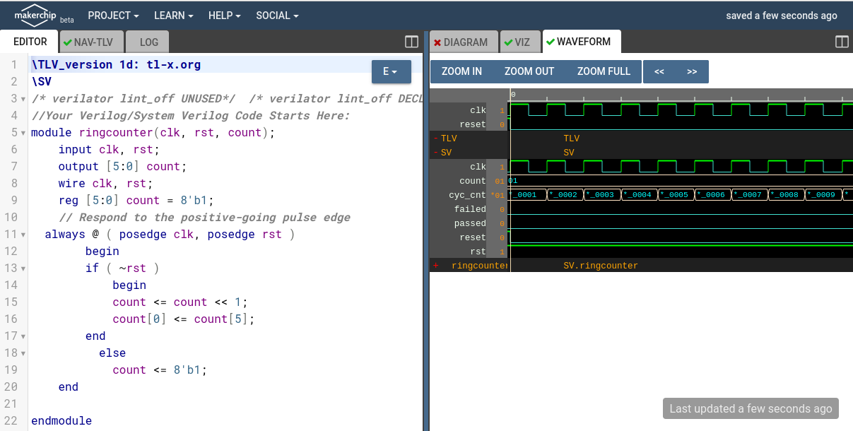
module ringcounter(clk, rst, count);
input clk, rst;
output [5:0] count;
wire clk, rst;
reg [5:0] count = 8'b1;
// Respond to the positive-going pulse edge
always @ ( posedge clk, posedge rst )
begin
if ( ~rst )
begin
count <= count << 1;
count[0] <= count[5];
end
else
count <= 8'b1;
end
endmodule
//Top Module Code Starts here:
module top(input logic clk, input logic reset, input logic [31:0] cyc_cnt, output logic passed, output logic failed);
logic rst;//input
logic [5:0] count;//output
//The $random() can be replaced if user wants to assign values
assign rst = $random();
ringcounter ringcounter(.clk(clk), .rst(rst), .count(count));
\TLV
//Add \TLV here if desired
\SV
endmodule

* /home/hemanth/esim-workspace/ringcolmult/ringcolmult.cir

.include smttrigger21.sub
.include avsd_opamp.sub
.include ringoscillator.sub
.include "/usr/share/local/sky130_fd_pr/models/sky130_fd_pr__model__inductors.model.spice"
.lib "/usr/share/local/sky130_fd_pr/models/sky130.lib.spice" tt
.include "/usr/share/local/sky130_fd_pr/models/sky130_fd_pr__model__diode_pd2nw_11v0.model.spice"
.include "/usr/share/local/sky130_fd_pr/models/sky130_fd_pr__model__r+c.model.spice"
.include "/usr/share/local/sky130_fd_pr/models/sky130_fd_pr__model__linear.model.spice"
.include "/usr/share/local/sky130_fd_pr/models/sky130_fd_pr__model__pnp.model.spice"
.include "/usr/share/local/sky130_fd_pr/models/sky130_fd_pr__model__diode_pw2nd_11v0.model.spice"
xsc2 net-_sc1-pad1_ inte_out sky130_fd_pr__cap_mim_m3_1 W=99 L =999 MF=1
x1 net-_x1-pad1_ gnd gnd net-_sc1-pad1_ inte_out gnd avsd_opamp
xsc1 net-_sc1-pad1_ vin net-_sc1-pad3_ sky130_fd_pr__res_generic_nd W=1 L=9900 MF=1
xsc3 gnd inte_out net-_sc1-pad3_ sky130_fd_pr__res_generic_nd W=1 L=9000 MF=1
* u1  inte_out mux_in net-_u1-pad3_ net-_u1-pad4_ adc_bridge_2
* s c m o d e
v4  mux_in gnd sine(0 3.3 70 0 0)
* u2  net-_u1-pad3_ net-_u1-pad4_ net-_u2-pad3_ mux_out m21
v1  vin gnd sine(0 3.3 50 0 0)
v3 net-_x1-pad1_ gnd  dc 5
v2 net-_sc1-pad3_ gnd  dc 5
v5  net-_u3-pad1_ gnd pulse(0 5 0 5n 10n 10m 20m)
* u3  net-_u3-pad1_ net-_u2-pad3_ adc_bridge_1
* u7  mux_out net-_u7-pad2_ dac_bridge_1
x2 net-_u7-pad2_ gnd ringosc ringoscillator
x3 ringosc net-_x3-pad2_ smt_out smttrigger21
v6 net-_x3-pad2_ gnd  dc 5
* u4  net-_u4-pad1_ gnd net-_u19-pad1_ net-_u19-pad2_ net-_u19-pad3_ net-_u19-pad4_ net-_u19-pad5_ net-_u19-pad6_ ringcounter
* u5  smt_out net-_u4-pad1_ adc_bridge_1
* u13  count5 plot_v1
* u14  count4 plot_v1
* u15  count3 plot_v1
* u16  count2 plot_v1
* u17  count1 plot_v1
* u18  count0 plot_v1
* u11  smt_out plot_v1
* u8  ringosc plot_v1
* u12  mux_out plot_v1
* u9  inte_out plot_v1
* u10  mux_in plot_v1
* u6  vin plot_v1
* u19  net-_u19-pad1_ net-_u19-pad2_ net-_u19-pad3_ net-_u19-pad4_ net-_u19-pad5_ net-_u19-pad6_ count5 count4 count3 count2 count1 count0 dac_bridge_6
a1 [inte_out mux_in ] [net-_u1-pad3_ net-_u1-pad4_ ] u1
a2 [net-_u1-pad3_ ] [net-_u1-pad4_ ] [net-_u2-pad3_ ] [mux_out ] u2
a3 [net-_u3-pad1_ ] [net-_u2-pad3_ ] u3
a4 [mux_out ] [net-_u7-pad2_ ] u7
a5 [net-_u4-pad1_ ] [gnd ] [net-_u19-pad1_ net-_u19-pad2_ net-_u19-pad3_ net-_u19-pad4_ net-_u19-pad5_ net-_u19-pad6_ ] u4
a6 [smt_out ] [net-_u4-pad1_ ] u5
a7 [net-_u19-pad1_ net-_u19-pad2_ net-_u19-pad3_ net-_u19-pad4_ net-_u19-pad5_ net-_u19-pad6_ ] [count5 count4 count3 count2 count1 count0 ] u19
* Schematic Name:                             adc_bridge_2, NgSpice Name: adc_bridge
.model u1 adc_bridge(in_low=300m in_high=450m rise_delay=1.0e-9 fall_delay=1.0e-9 )
* Schematic Name:                             m21, NgSpice Name: m21
.model u2 m21(rise_delay=1.0e-9 fall_delay=1.0e-9 input_load=1.0e-12 instance_id=1 )
* Schematic Name:                             adc_bridge_1, NgSpice Name: adc_bridge
.model u3 adc_bridge(in_low=300m in_high=450m rise_delay=1.0e-9 fall_delay=1.0e-9 )
* Schematic Name:                             dac_bridge_1, NgSpice Name: dac_bridge
.model u7 dac_bridge(out_low=0 out_high=5 out_undef=0.5 input_load=1.0e-12 t_rise=1.0e-9 t_fall=1.0e-9 )
* Schematic Name:                             ringcounter, NgSpice Name: ringcounter
.model u4 ringcounter(rise_delay=1.0e-9 fall_delay=1.0e-9 input_load=1.0e-12 instance_id=2 )
* Schematic Name:                             adc_bridge_1, NgSpice Name: adc_bridge
.model u5 adc_bridge(in_low=300m in_high=450m rise_delay=1.0e-9 fall_delay=1.0e-9 )
* Schematic Name:                             dac_bridge_6, NgSpice Name: dac_bridge
.model u19 dac_bridge(out_low=0 out_high=5 out_undef=0.5 input_load=1.0e-12 t_rise=1.0e-9 t_fall=1.0e-9 )
.tran 0.01e-00 0.1e-00 0e-03

* Control Statements
.control
run
print allv > plot_data_v.txt
print alli > plot_data_i.txt
plot v(count5) +2 v(count4)+4 v(count3)+6 v(count2)+8 v(count1)+12 v(count0)+14 v(smt_out)+16 v(ringosc)+18 v(mux_out)+20 v(inte_out)+22 v(mux_in)+24 v(vin)
.endc
.end


- Open eSim
- Run NgVeri-Makerchip
- Add top level verilog file in Makerchip Tab
- Click on NgVeri tab
- Add dependency files
- Click on Run Verilog to NgSpice Converter
- Debug if any errors
- Model created successfully
- Open a new terminal
- Clone this project using the following command:
git clone https://github.com/Hemanth432?tab=repositories - Change directory:
cd https://github.com/Hemanth432/Mixed Signal SoC design Marathon using eSim & SKY130 - Run ngspice:
ngspice ringcolmult.cir.out - To run the project in eSim:
- Run eSim
- Load the project
- Open eeSchema
- FOSSEE, IIT Bombay
- Steve Hoover, Founder, Redwood EDA
- Kunal Ghosh, Co-founder, VSD Corp. Pvt. Ltd. - kunalpghosh@gmail.com
- Sumanto Kar, eSim Team, FOSSEE
- IIT Bombay website : http://iitb.ac.in
- Google Website : https://www.google.co.in
- FOSSEE Website : https://fossee.in
- Spoken tutorials : https://spoken-tutorial.org
- VSD Website : https://www.vlsisystemdesign.com
- Chips to startup website : https://www.c2s.gov.in
- Website: "https://www.allaboutcircuits.com/"