Circuit Diagram #1
Comments
|
Maybe you are looking for this one?
El 8 dic. 2016 10:14 PM, "kamranshahidbutt" <notifications@github.com>
escribió:
… Dear can you please share the circuit diagram how's we need to connect the
circuit.
—
You are receiving this because you are subscribed to this thread.
Reply to this email directly, view it on GitHub
<#1>, or mute the
thread
<https://github.com/notifications/unsubscribe-auth/AUNAzmXpuuX-_t1Cs_VrR53gPzAICHavks5rGHMZgaJpZM4LISsr>
.
|
|
Dear i am looking for Schematics |
|
Hi, it is quite easy to wire up. It´s an old one I found, but maybe it helps: Anything else can be found here: |
|
FWIW I have reproduced this schematic but had to reverse RX and TX for the bluetooth:
Otherwise the connection wouldn't work. I still couldn't have the device speak with my bike (Versys 650). I could connect to it though. @HerrRiebmann the pull up is needed between VCC (5V) or VIN (12V)? |
|
Another guy on an American forum has posted what looks like a good version of the circuit: The capacitor is 10nf and the resistor is 510 Ohms. |

|
Yes, that is the right one! |
|
Updated the Readme on the Dokumentation-Section: |

|
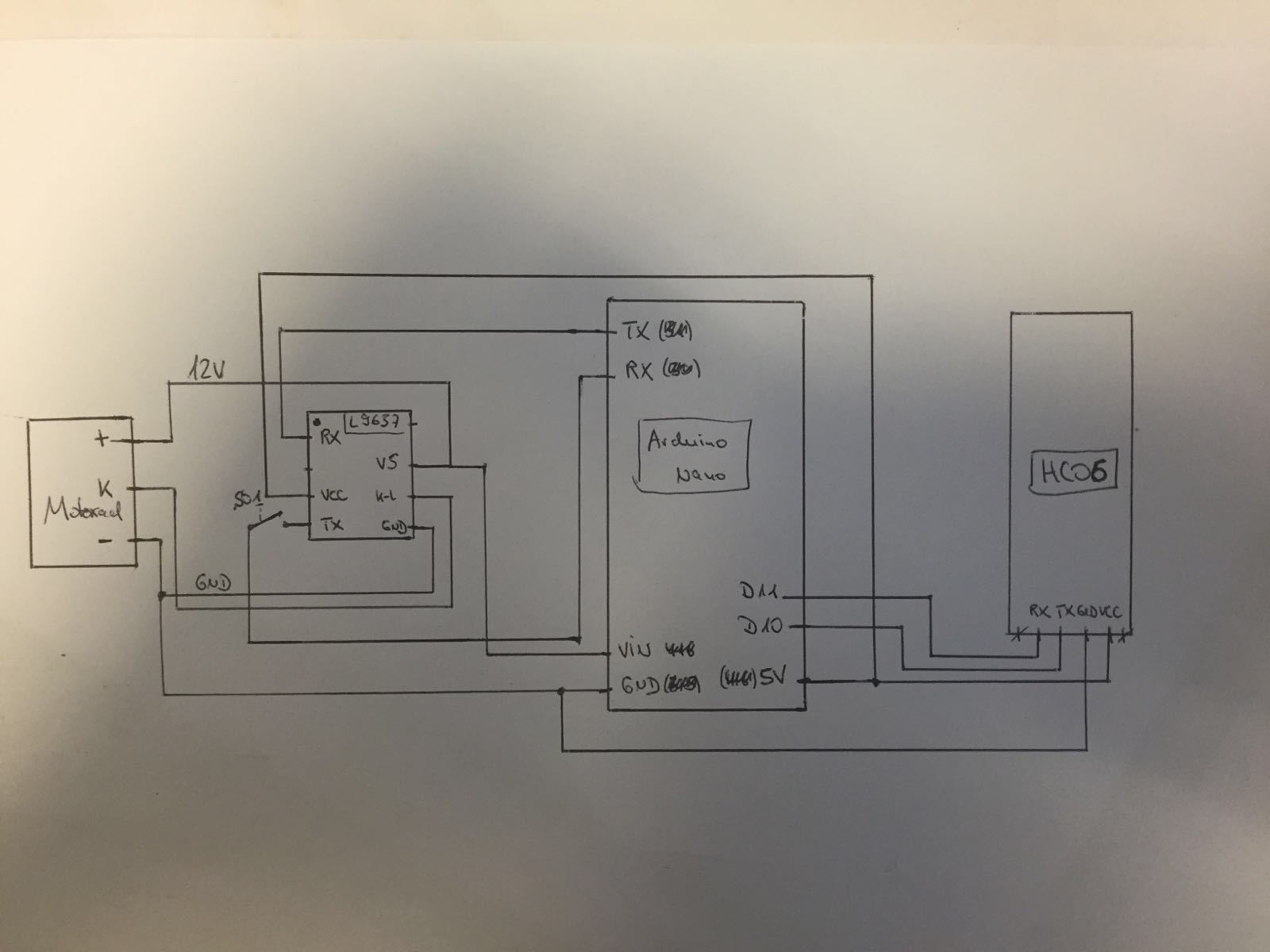
I am newbie and have a question about your new schematic. I dont understand the "left" side of the shematic, is my schematic below ok?
|

|
Hey has anyone tried using a ELM327 instead?? Looking for a easy way |
|
If it easily would be possible just to connect a ELM327 (or a cheap china clone), do you think we all would spend so much time and work into that? ;) Theoretically this might be possible. But you have to reconfigure the initial process, manually. Then change the timings, baud, SID´s, header, format and more. This is possible, but needs to be done via bluetooth somehow. Then you still do not have matching PIDs, nor the calculations will fit. Long story short: Might be possible, but needs some research and testing. And you cannot use any stock device to receive the data. You have to develop this yourself. |
|
I do understand that your project was a task and i did get all the stuff to do it before i read another forum. I just asked as some on the zx-10r forum managed to get that done and hence asked FYI - The Links https://www.zx-10r.net/forum/f23/clearing-ecu-codes-obdii-scanner-349538.html https://www.zx-10r.net/forum/f23/obdii-zx10r-bluedriver-320554.html |
|
This won´t work for any bike without EURO 4 homogenisation (Which started 2017-01-01). As you can see in the video from the second link, the PID´s are pretty standard (0x0C for RPM). All Kawasaki´s (Bikes, Jetski, ATV, ect.) between 2007-2017 use 0x09. It seems, that the bikes now, really support OBD II, and you just need a plug/cable to make an ELM327 work. That was announced by law, but I never got any further information about this (And if this is only be done in Europe) until yet :) I got all the stuff here to create a plug for a few cents, without cutting any cable. Maybe I´ll contact my dealer :D |
|
ZX10R is another story, that works for Gen5+ = 2016 models+ |
|
The dealers here are not helpful. and I rely on the internet where it becomes even more confusing |
|
another improved working diagram |


|
how do i identify the pins of the L9637. The IC is way to small and as far as i see there is no marking of pin no etc |
|
upper left is 1, one side has different edge!
|


The dealer should not do anything, I want to test it myself with a borrowed bike :) Exactly, the most L9637D´s does not have the cut in the top. They have a flat edge on one side. |
|
is these the correct resistors etc?? |

|
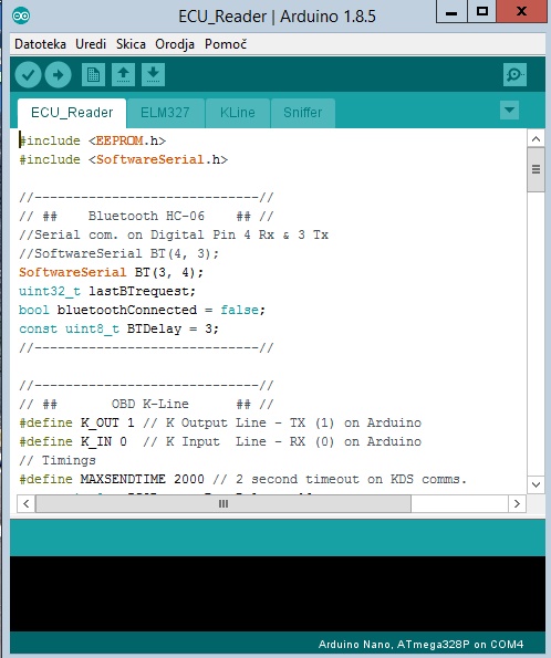
Do i need to update all 4 .io files to arduino?? |
|
yes, all 4 |
|
I have uploaded all the 4 sketches one by one (sniffer, kline,elm327 and then ecu_reader) Is there any other way to upload. Sry but couldnt find any tutorials online |
|
You should open all 4 sketches (see my screenshot, 4 tabs), connect the device and press button send... |
|
Erased the old sketch and uploaded the fresh sketch. The Torque app is connecting to the bike and shows connected to ECU but nothing happens. No rev counter and shows transmission faults. When i try to clear it the device disconnects and doesnt re-connect unless powered down and on again |
|
Try to use a Bluetooth Serial Monitor App. Then you can better see what happens! |
|
I am using the same code from Github. is it because i didnt use the 20K and 10K ?? |
|
I think so, you have to pullup the dataline, to straighten the signal. |
|
I have added the 20k and 10k as well as per the diagram above but doesnt seem to still read the ECU. Should i try this instead of the american one shared by snecer?? Fyi - My motorcycle is a ninja 300 non abs |

|
mine diagram is working
|


|
@HerrRiebmann I am facing the same issue when I attempted to design the PCB. I dont have a clue how to do it. @Snecer - can you share the pcb image or design so i get one printed for me. Due credit will be given. My attempt at trying to get the DIY board is nowhere hence a PCB with all things assembled may help |
|
@Snecer Can you help |
|
PCB was friend's design, will try to find the file.
|


|
HW works ok, but it seems that SW is not optimized, i also couldn't find a string for speed, must be different as for z750. Thats not a big issue, because gps has that data. |
|
@Snecer Please do let me know if you find it. TY in advance |
|
Any Update?? |
|
No. Find someone who can draw a PCB. |
I've found someone, who will draw the PCB. |
|
@Snecer that would be great. How do i contact |
|
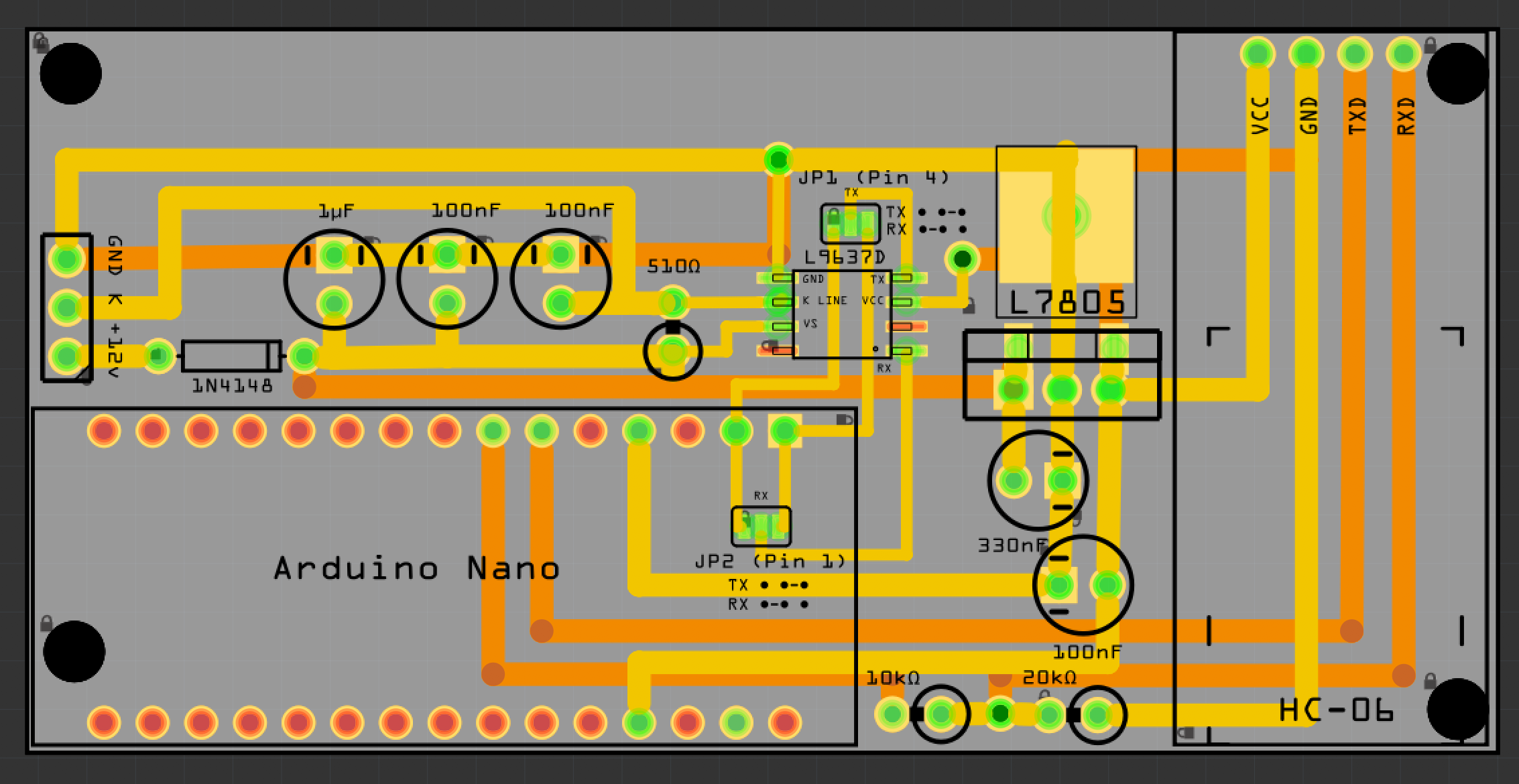
I've made this so far using Fritzing - does it look right? I want to make sure I've not missed anything or connected wrong? Once confirmed I will share Gerber Files to use with JLCPCB or what ever PCB company you want PS: JP1 and JP2 is a solder bridge - in case someone uses a chip with same layout but RX and TX are switched. So you choose which if "RX" is actually RX or TX, and the same to "TX" of the chip (L9637D) Yellow tracks are on the top layer of the board, orange tracks are on the bottom layer. If someone can confirm and let me know the wattage of resistors, I can improve the design with SMD 1206 resistors. Also capacitor spec - atm the design uses 5mm diameter polarised alu caps I'm hoping to be able to use this with my BMW Z4 with K-Line
I have made my own PCB about 10 times now for different projects so I am used to using Fritzing to design PCBs |

|
excellent, will ask my friend, he is also working on pcb |

Thanks - that looks much better than mine! I have Eagle too - although for simplicity I use Fritzing. Will your friend be willing to share his .brd and .sch files? |
Here some .brd files (alpha version). |
Awesome, thanks. I was hoping they would contain the values of the resistors etc but it doesn't ha. Sods law! It shows package details, but the value field has been left blank on all of them. |
|
Hey @IAmOrion @Snecer @HerrRiebmann Has there been any update. Cause I have shelved this DIY cause i dont know where i am going wrong. Probably I have got some diodes/resistors or wiring wrong i dont know. Unfortunately i dont have any friend who can help. Hence was looking forward to the board |
I changed my design as I managed to get a load of TH3122.4 chips off of AliExpress (Although I've yet to test them but others have reported they work as expected) I'm too much of a PCB Design novice for Eagle or EasyEDA - but you're welcome to my Gerbers to get them produced.
JLCPCB will make 5 boards for $2 - shipping will obv depend on your location. I paid just over £9 GBP to have 30 boards made and posted to the UK economy recorded postage
Still waiting for them to arrive :) Gerbers: For what it's worth, I MAY revisit this using the L9637D but I couldn't find enough info of the circuit required - I mean, I found dozens of circuits, but they never showed the capacitor values and I don't know enough to work out what I would need and I couldn't get anyone to reply to me so I stopped working on it. This as far as I got with the L9637D (I can't remember is this is complete or not)
Gerbers: Fritzing: |


|
Ive got the L9637D chip. Sourcing these tiny bits in India is a task altogether. None of the sites have all parts. |
|
So I have built this and connect tot he Bluetooth via Torque light. Could somebody let me know what connector and color wire I connect to on a 2011 Versys 650? I have power ground and have have traced back from my ECU for both the self diag terminal and the Kawasaki Self diag terminal. Is it the 6 pin connector or 4 pin? Cheers |
|
check the link
https://www.alter.si/tema/majster-za-arduino.2635004/page-2
V V sob., 3. jul. 2021 ob 20:39 je oseba Mattbatt84 <
***@***.***> napisala:
… So I have built this and connect tot he Bluetooth via Torque light. Could
somebody let me know what connector and color wire I connect to on a 2011
Versys 650? I have power ground and have have traced back from my ECU for
both the self diag terminal and the Kawasaki Self diag terminal. Is it the
6 pin connector or 4 pin? Cheers
—
You are receiving this because you were mentioned.
Reply to this email directly, view it on GitHub
<#1 (comment)>,
or unsubscribe
<https://github.com/notifications/unsubscribe-auth/AIT5YIGVRFJNPGOQFDJW4MLTV5KPRANCNFSM4CZBFMVQ>
.
|
|
Is anyone using the Torque lite Android app? I have successfully connected to Bluetooth but seem to get any further than that. Does the app connect instantly or do you need to wait? |
I am using Torque Pro. |
|
Yes, I also use Torque lite, Car Scan and RaceChrono. Just did a completely rewrote of my code. Now with Suzuki & Kawasaki combined, much more performance and error-logging. So I will create a new repository with at least all the features from this one, but more relyable. |
|
@HerrRiebmann Great news. I currently have two bikes in the works and plan on building my own dashboards for each one. So a Suzuki port of the software is wonderful. Thank you for all your hard work. I might be able to bend metal to my will....code not so much :) |
|
After a lot of thinking my wiring was the issue I have used the emulator to check and all wiring and components are good the issue is the KLine coming from the bike. I even traced the kline back the to ecu based on the manual. Torque lite jut does not pick up that the bike is connected. I have a 2011 versys 650. Has anyone else had similar problems and found a solution? |
|
@Roughd1433 you can see how it works on my Suzuki. Its much better then on Kawasaki, since I introduced a data storage. @Mattbatt84 oh, that reminds me of releasing the latest version of the emulator, as well! |
|
@HerrRiebmann You were right it was the L9637D. I must have popped it prototyping a new board. I am going to purchase a few more a well as a MC33199 and have a crack at using that as it has a transmission Baud rate up to 200kBaud. See if makes a difference. Will also publish the EASYEDA files once done so people can order from PCBway or JLPCB as there pick and place services will do all the little 0806 bits as the I will be adding TX RX leds to the kline chip to diagnose nonsense like I have been having. |
|
This project is getting expensive. £30 for the boards £30 Parts £30 in broken prototypes. All to see error codes hahahahha. |

|
Wow! That is really expensive! But don´t ask me about all my prototypes, parts and unassembled boards... I guess this could leave the three-digits ;) But all in all, that board-design really looks good! Quite compact! |
|
I looked at jlpcp but they were quoting £135 for 5 boards pre assembled and 25% of the parts were not available. I went with boards only and parts I do not have from ebay. The costly bits were the ATMEGA32U4-MU £8 and L9637D £5. But I am also being impatient and paying premium for parts that are next day shipping soooooooo. If I was willing to wait I think I would be looking at £40 for 5 assembled boards. |
|
@Snecer link has expired, could you please share again? |
Dear can you please share the circuit diagram how's we need to connect the circuit.
The text was updated successfully, but these errors were encountered: