Home
This is a brief introduction to paper Lidar with Velocity: Motion Distortion Correction of Point Clouds from Oscillating Scanning Lidars , the paper and the github repository link is shown as blow.
paper: https://arxiv.org/abs/2111.09497
code: https://github.com/ISEE-Technology/lidar-with-velocity
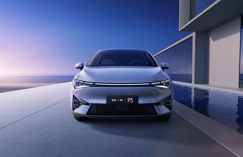
Now Lidar is playing an increasingly important role in autonomous driving perception. Compared with the camera, it can provide an accurate 3D description of the target, which can help the vehicle perceive the surrounding environment better. Traditional mechanical Lidar like Velodyne is difficult to be deployed on vehicles due to their high cost. But in the recent years, many semi-solid Lidars and solid Lidars have got the attention of OEMs. These Lidars can provide high-quality pointcloud with low price, which propose a suitable solution to the perception problem of autonomous driving. For example, at the 2021 Shanghai International Automobile Industry Exhibition, many leading car manufacturers have unveiled their vehicles equipped with the new Lidars

Although these new lidars has many advantages, the shortcomings can not be ignored. These Lidars all measure based on the TOF (time of flight) principle. The distance can be calculated from the flight time of the modulated laser signal. In one pointcloud frame, the emission time of each laser point is not exactly the same, but there is a certain offset, which causes the pointcloud distortion. The distorted points deviate from the actual position of the object, which will confuse the vehicle's perception system and may bring servious hazards.
So in this paper, the author mainly discussed the point cloud distortion characteristics of the emerging oscillating scanning Lidar such as Livox, and proposed a fusion system based on Lidar and camera to compensate the distortion in real time. Besides, it can also estimate accurately estimated the velocity of the objects, as shown in the following video:
First, we need to know what is Distortion ?
As mentioned earlier, the most fundamental reason for pointcloud distortion is that the laser emission within one frame is not synchronized. which is caused by the relative motion between the Lidar and the object. This asynchrony is related to Lidar's scanning pattern. So in this section we will take the traditional rotating Lidar Velodyne and the semi-solid radar Livox Horizon as examples to explore the source of distortion.
The following video shows the difference in pointcloud scanning between Livox Horizon and Velodyne. Video source link
The red points indicates the area being scanned by the lidar, which can be divided into two parts. The one rotating 360° clockwise is Velodyne, and the one oscillating right and left in front is Livox Horizon. Within the time of one frame (usually 100ms), Livox scans the front objects multiple times. As shown by the following video, the left one represents the scanning pattern of the Livox Horizon, and the right one shows the process of the increasing the pointcloud density within one frame over time. At this time, if there is a relative speed between the front target and the Lidar, the point cloud will be blurred.
Based on the source of the velocity, the type of distortion can be divided into two parts, the ego-motion distortion and the observed target motion distortion. Both of these two types behave the same, the difference comes from the Lidar scanning pattern. The following picture the different distortion characteristics caused by the different scanning methods.

The left side represents Velodyne, the right side represents Livox Horizon, and each frame contains 100ms. If the stationary relative to the Lidar, the point cloud corresponds to the shape of the vehicle and won't be distorted as shown by the black points below. If the target is moving forward, the distortion of Velodyne can be represented by the red points on the left. There is only a slight positional deviation caused by the speed. But the Livox points will have multiple blur due to repeatedly scans of the target in one frame, which is shown by the red points on the right.
So to solve this distortion problem and get the real pointcloud of the object. This paper proposed a fusion method based on camera and Lidar to compensate the distortion. Full velocity estimation is not trivial with lidar points along. Lidar provides a direct distance measurement. cameras can provide essentially high angular resolution measurements, but no direct distance (radial) measurement. As shown below:

Comparing to the the state-of-the-art Velodyne HDL-64E outputs 0.13 million points per frame, as compared to 2 million pixels per frame from a standard 1080p camera. Therefore, fusing camera and lidar together for a full 3D velocity estimation combines the strengths of both. So In this paper, there are these three following contributions:
- We construct a probabilistic sensor fusion algorithm combining the strengths of camera and lidar information for a full and accurate 3D velocity estimation.
- The lidar points distortion from oscillating scanning lidars can be corrected to an excellent accuracy, important for the adoption of emerging lidars.
- We provide a complete system from the frontend sensor detection to the backend tracking with real time performance. We open-sourced the code and dataset on GitHub.
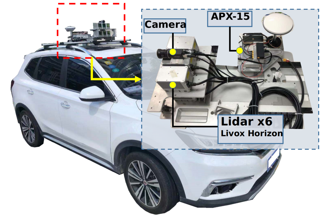
Our hardware system is illustrated in the following fig. We choose Livox Horizon lidars as an example of oscillating scanning lidars. Six Livox Horizon lidars were mounted on top of the moving vehicle. In order to obtain a thorough evaluation, we aligned their field of view (FoV) to obtain an extremely dense point cloud. A RGB camera is mounted with the same FoV as lidars to detect the moving objects and estimate their tangential movement velocity. A GNSS-Inertial system (APX-15) is utilized to accurately measure the ego motion for ego motion distortion correction. The lidars and the camera are triggered by the same TTL signal synchronously at 10 Hz. The APX-15 module runs at 100 Hz and syncs with the other sensors. The whole system is mounted on top of a car and real road scenarios data are gathered.
With this set of sensor hardware, we proposed a systematic framework to evaluate the moving object velocity and correct the distortion. The extrinsically calibrated Lidar and camera data are fed into the prepossessing stage. In the detection part, the moving object needs to be identified, and this can be accomplished with image detection such as YOLO or point cloud detection or both. Once an object is identified, the object image and the associated point cloud are used separately for their respective optimization and velocity estimation at frame rate. Note here that these velocities are ego-motion corrected and thus represent the object velocity in the world coordinate. A probabilistic fusion of these two velocities is performed to obtain a fused velocity. This velocity is then fed into a Kalman filter process as a measurement, and a final velocity is computed for each tracked object from the KF process. Finally the distorted point cloud of each moving object in the frame are corrected according to the final velocity and point cloud quality is evaluated. The pipline can be shown in the following fig.

A unified coordinate is required as the first pre-processing step for all the sensors. Calibrations are performed for all the sensors and they are transformed into the same coordinate. Then we apply the motion compensation to all the points in FOV. After the correction, the points belong to the static objects is completely accurate, but the points belong to the moving objects are still distorted.
After removing the ego-motion distortion, we have to detect the moving objects and associate the lidar points to the object. At each frame, the camera detects the moving objects and the ROI bounding boxes by the YOLO algorithm. And the corresponding points are detected by the through the Livox detection algorithm. We calculate the projection IOU score to determine whether the pixels and the points belong to the same object.
The velocity measurement can be decomposed into two orthogonal directions. Cameras can measure tangential directions (polar and azimuthal directions in spherical coordinates) velocity more accurately due to higher resolution(red arrow), while lidars could measure both tangential and radial directions. Fusion of two sensor modalities in tangential directions is beneficial(brown arrow).

For camera measurement, we applied the KLT sparse optical flow algorithm to estimate the motion in consecutive frames. A RANSAC method is also used to remove the outliers. Then the 2D velocity in pixel domain will be back projection to the 3D space with the corresponding depth and the camera intrinsic. And the covariance of the velocity will be regarded as the confidence of the optical flow.
Lidar provides another modality from the camera. The contribution of the lidar are two folds . First, the direct distance measurement allows one to estimate the movement of the object along the radial (depth) direction. This is missing from the camera modality. Second, although relatively sparse, the lidar points could still be used to estimate the tangential velocity, with computed covariances that is ready to be fused with camera modality. We propose a novel optimization method to estimate object full velocity from lidar. This velocity will be projected onto the radial direction and the tangential directions. The radial part will be used as the estimated object radial velocity while the tangential part will be fused with the camera measurement to combine strength from both modalities.
Finally the comprehensive velocity is composed of the two velocity estimated by camera and Lidar respectively. The fusion process is divided into two different directions. The radial velocity of the object comes from the Lidar measurement only, and the tangential velocity consider both Lidar and camera. The fusion weight is similar to the kalman gain. Finally the fused velocity with its corresponding covariance will be input to the measurement value to KF backend process to augment the tracking.
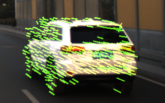
The following fig demonstrates the results of distortion correction and the augmenting capability from camera.

When the velocity is only optimized with point cloud from lidar (third row), corrections are slightly lacking in the tangential direction, as compared to correcting from both lidar and camera (fourth row). Note that point cloud from all six lidars were used for display and evaluation, but only one lidar was used in optimization. Kalman filter (KF) is used as the backend to provide better continuous velocity estimations. Comparatively, the ICP based KF method from traditional 360° rotating type point clouds underperformed due to the increased blurriness from the new lidars’ oscillating scan.
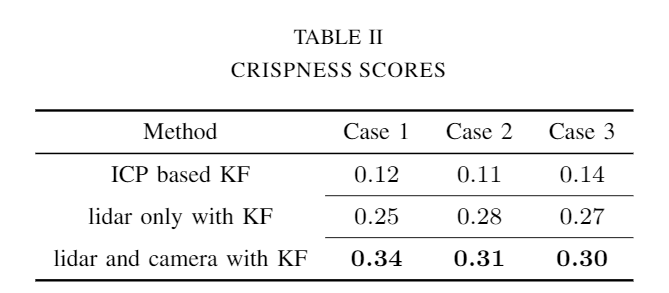
For there are no groundtruth about the object velocity, to quantitatively evaluate the point cloud distortion correction, we use the crispness score proposed by Mark Sheehan to represent the quality of the undistorted pointcloud. Larger crispness value means crisper point cloud and more accurate velocity. The following table shows the corresponding result of the quantitative evaluation.
The following video gives a brief intro about how our system work. For more details, please read our paper. If you have any questions or ideas, please issue us on github. Thanks.
paper: https://arxiv.org/abs/2111.09497
code: https://github.com/ISEE-Technology/lidar-with-velocity