BlenderBim IfcRepresentation ELEVATION_VIEW does not flatten the representation in the correct axis #2472
Comments
|
This is a more fundamental problem initially brought up as a question here: #1153 (comment) The problem is that any Plan context, such as Plan/Annotation/ELEVATION_VIEW only stores 2D XY coordinates, so therefore we are at the mercy of the orientation of the window itself. This is fine for actual Plans, but means that it's actually impossible to flatten in the "correct axis" because we're in a 2D world ... there is only one way you can flatten it. The correct solution is to allow for 3D annotations, as well as 3D annotations that "accompany" a 3D body. That way, you can have a full 3D body window in an elevation which also has those annotated triangles "superimposed" on them to show how the windows swing. This creates a breaking change, as previously annotations would "replace" the 3D body, whereas now we'll show both. Note that you can now also override the body itself in a particular target view. I'll find some time when this matures to create a few examples demonstrating how this solves a number of documentation problems. If you have an old file that breaks as a consequence and want to recover it, let me know and I can help. |
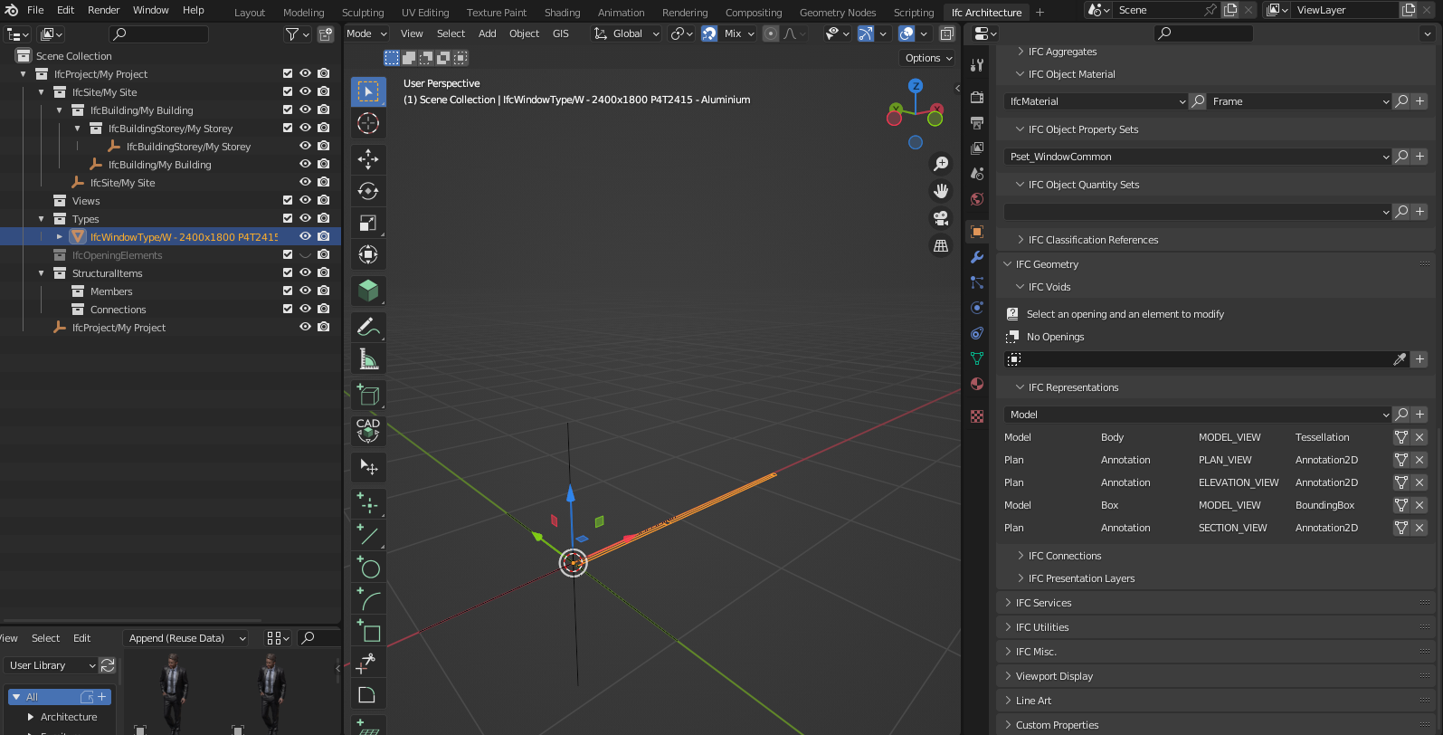
When creating an IfcType such as a window, there are 3 2D representations that can be attached:
The plan annotation view
The elevation view
and the section view
While the Plan view works no problem:
And the tesselation is present:

Both the elevation and section views get flattened in the Z direction same as plan but should be flattened in another direction

The IfcRepresentation Plan-Annotation-ELEVATION_VIEW Annotation2d does not does not flatten the representation in the correct axis.
Here is the ifc file:
W - 2400x1800 - Alum - Copy.ifc.txt
Just remove the .txt
The text was updated successfully, but these errors were encountered: