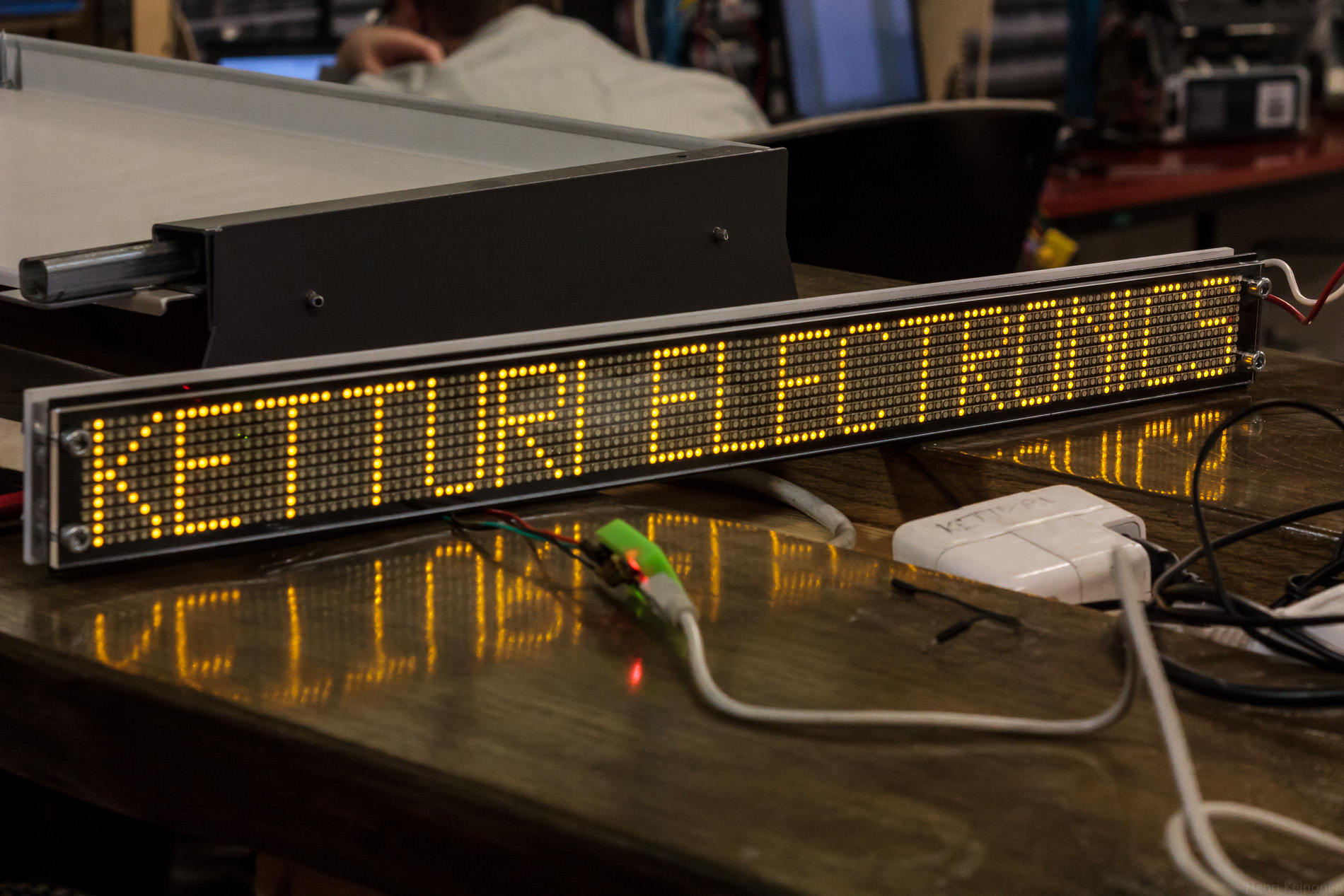
128x10 LED matrix IoT display.
ESP8266 WiFi module controls daisychained 32x10 led display units.
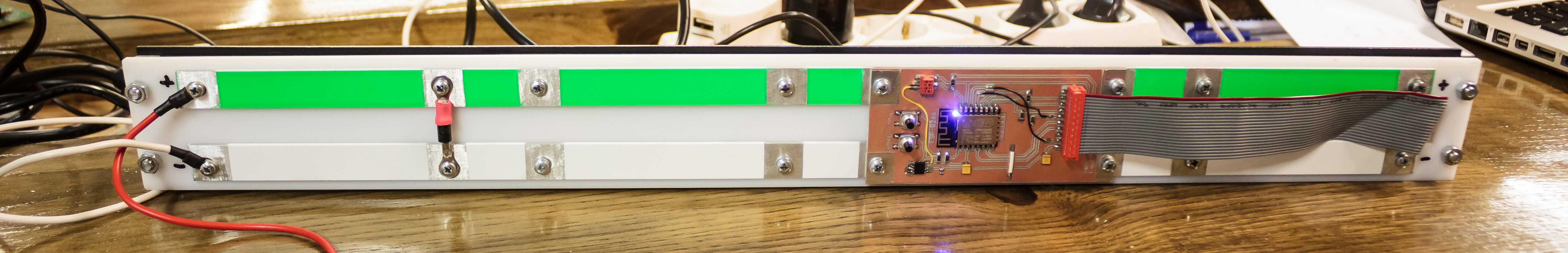 Custom build enclosure to hold four display modules, their interlinking cables, power busbars and controller board together. Acrylic parts are lasercut from dxf images designed in Autodesk Fusion360.
3D CAD Model in A360.
Custom build enclosure to hold four display modules, their interlinking cables, power busbars and controller board together. Acrylic parts are lasercut from dxf images designed in Autodesk Fusion360.
3D CAD Model in A360.
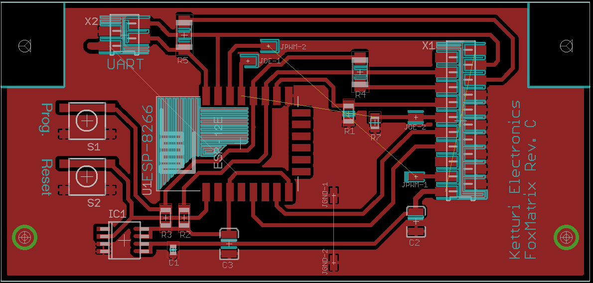
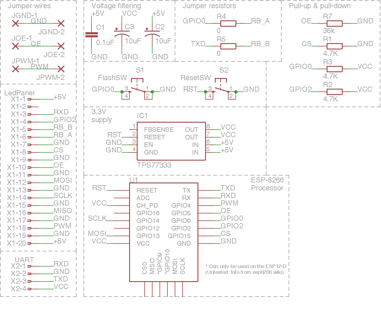
Control board for connectinc ESP8266 module to display modules is designed in eagle and is made by milling it with CNC routter.
Display modules are connected to ESP8266 with high speed SPI for matrix column data, and 4 parallel lines for matrix row address.
 Display modules used in this single prototype are propriety, and do not contain make or model. There is no other available information of these, and all work here is done trough reverse engineering.
Code and control board is easily adaptable to publicly obtainable LED matrix displays.
Display modules used in this single prototype are propriety, and do not contain make or model. There is no other available information of these, and all work here is done trough reverse engineering.
Code and control board is easily adaptable to publicly obtainable LED matrix displays.
ESP8266 module runs arduino sketch. Arduino IDE needs Board core files to be able to compile software for module. Use the arduino.org IDE 1.7.9! Arduino.cc IDE is not working due issues with arduino-builder. You need to install board files and libraries manually.
Simple function converts binary bitmap data to column data corresponding selected row and column. Data is then transferred trough SPI to column led drivers (32 bit shift register in each module daisychained together) Row is selected trough 4-bit address.
Software incorporates OTA updates through Arduino IDE. When ESP8266 is connected to same network as computer containing IDE, board shows in port menu.
ESP8266 uses WiFi Manager library that allows modifying wlan credentials and other settings without recompiling and uploading the software. When control board is powered, it tries to connect previously saved WiFi access point. If that however fails, ESP8266 creates access point itself. By connecting this access point user can go to http://192.168.4.1 address and input their own WiFi credentials. Credentials are saved to flash, and ESP8266 tries to connect that access point. After successful connection display is initialized and starts to show data.
| Setting | Option | Explanaition |
|---|---|---|
| Board | Generic ESP8266 Module | Install board from http://github.com/esp8266/Arduino |
| Flash Mode | QIO | Selects how flash is controlled, QIO = 4 data lines |
| Flash Size | 4M (1M SPIFFS) | 4MB flash IC, 1M file system (3MB for scetch&OTA) |
| Debug port | Disabled | Disables serial debug, serial lines used for data lines |
| Debug level | None | No debuging |
| Reset Method | ck | Does not matter, no serial programming reset ability |
| Flash Frequency | 40Mhz | Probably 40Mhz, 80Mhz should be carefully tested |
| Upload Using | OTA | Updated over network |
| CPU Frequency | 160Mhz | Speed boost for faster display |
| Upload SPEED | 115200 | Does not matter when using OTA |
| Port | FoxMatrix at (Generic ESP8266 Module) | Select device from network, shows only when properly connected and discovered |
###Kukkaconvert Kukkaconvert.exe is small windows command line utility for converting PNG images to bitmap binary data for display. "kukkaconvert.exe image.png" accepts 12 pixel high png black and white images and outputs binary data to output.txt file.