Pressure advance smoothing induces e-axis position swings that scale with acceleration #4442
Comments
|
There's a scripts/graph_extruder.py tool that will graph out extruder motion (at least as it was intended to be implemented). For example, It would help if you could update that script with some problematic moves (see the Cheers, |

|
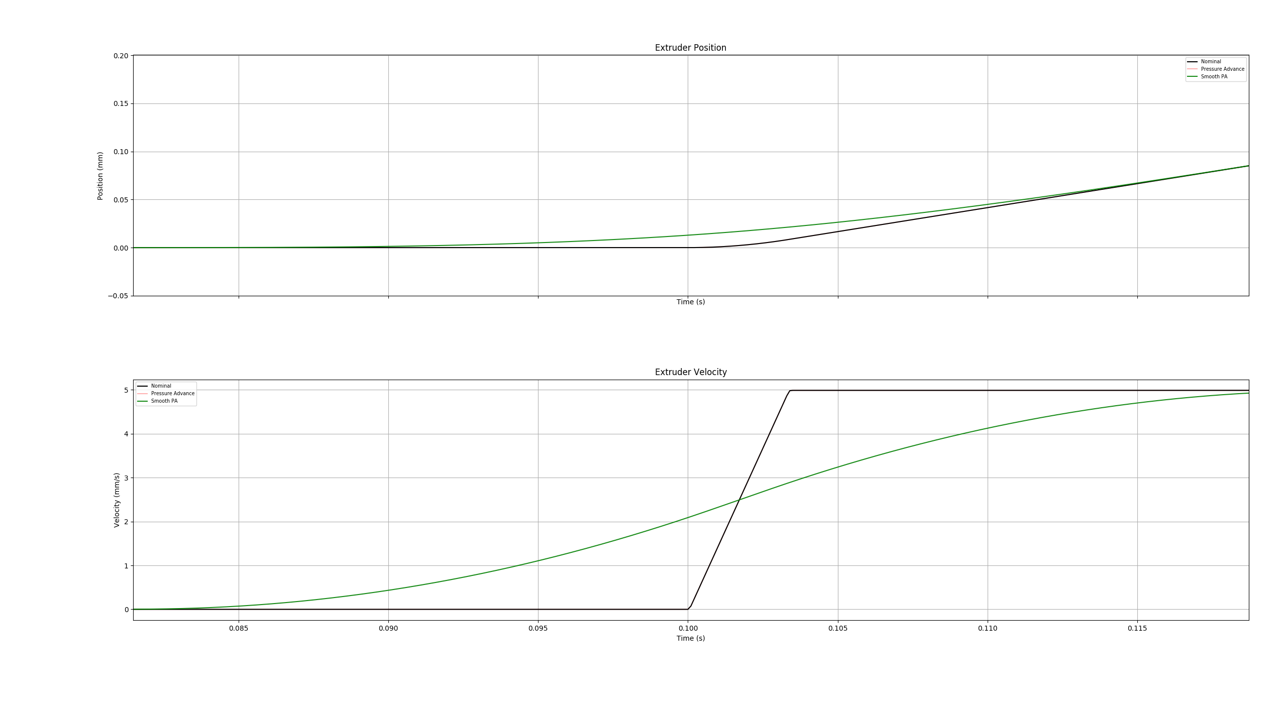
Thanks. I'll look at the script. I don't think it's instructive for seeing the problem though since it graphs velocity, not position, and the resulting function doesn't "look wrong" in this form. If you instead look at the position function, you'll see spans for which the offset that's been applied to the position is wrong. Do you have a good way to integrate the velocity graph to see position? Since the problem is orthogonal to the actual pressure advance, and the adjustments from pressure advance are juse "noise" that make it harder to see the effect of the smoothing on the base position, I think good test cases to see it will have advance set to something very low like 0.000001. |
|
I modified the I haven't applied the suggested change by @richfelker at this point to see how it changes the graph, but thought the modified script might be useful for a quick and dirty comparison. |

|
Here's the same setup (acc=30m/s², smooth_time=40ms) with a bit more PA=0.0025, comparing the smoothing of PA+nominal motion (green) against the smoothing of only PA (cyan): Another example where the smooth_time is closer to the acceleration duration (acc=15mm/s², smooth_time=10ms, PA=0.0025):
|


|
One thing I failed to mention above in my results: at least some of the difference/improvement can probably be attributed to smoothing no longer being applied to retractions. This makes retract/unretract a lot "sharper". It might be useful to make some graphs of retraction-like moves adjacent to print moves to see how they're affected. On the above graphs: what units are the accelerations in? E-mm/s² or spatial mm/s²? 30k on the E-axis makes no sense for a print move. If you want to simulate printing at 30k spatial accel, use ~1k E-accel, (1/30 = 0.2 mm * 0.4 mm / (2.4 mm³/mm), or maybe use 1/20 for speedboat-like settings). In testing smoothing just PA on real prints, I've found I seem to need a somewhat higher PA constant than before. This is likely because the "bump" when first accelerating to a higher speed was compensating somewhat for PA being too low (and becoming serious overextrusion at that point if the constant was set as high as it should be for sustained consistent extrusion). In my case I went from 0.05 to 0.10. This might need a higher smooth time window for very high speeds, but with the change higher smooth times have less impact on extrusion accuracy, so I think this is okay. |
|
The quoted accelerations are in toolhead units, so mm/s^2 in cartesian space. The graphs are in extruder mm and mm/s. |
|
@richfelker I agree that in general, integration of the main term may be unnecessary. And I agree with your general estimation of the deviation as a/6 * hst^2. However, the question is, what kind of velocities and accelerations are we talking about here? If we take a = 20000 mm/sec^2 as you suggested, what kind of velocity do you try to reach there? If (I just assume) it is 400 mm/sec for extrusion, then accelerating to this velocity takes only 0.02 sec - 2x less than the current default extruder smooth time of 0.04 sec. This actually means that when we integrate the acceleration part for extruder motion, that deviation becomes much smaller, as the integration is done not over the whole 0.04 sec period. I tried to generate the differences between the current smoothing schema and the schema when only the pa term is smoothed on the sequence of moves (as per script) with the target velocity of 400 mm/sec (for the toolhead), and the difference was there, but was rather quite small. So, most of the pre-extrusion (before the toolhead moves) seems to be from smoothing of the PA derivative term itself. Separately, there is a good question whether the default extruder smoothing window of 0.04 sec is appropriate for such high accelerations. The main goal of that smoothing is to smooth varying feed rates across multiple tiny moves (which may require rather big jumps in PA), and generally to put less stress on the extruder at the beginning of acceleration (and similarly for deceleration). But as it is here, the code actually has to average the extruder position too much across several "large" moves. So, perhaps the smoothing window must be adjusted in such cases? Could you try windows of 0.02 and 0.01 and see if that improves anything. Because that will reduce the smoothing of the PA term too, and you should have less overextrusion at the beginning of the moves. |
|
I normally use a smooth time of 0.01, and still found significantly improved extrusion consistency with the change. I have not analyzed the actual position functions for jobs I saw improvement on, so I'm not sure exactly what to attribute the change to, but it seems to be present. For some of them, it may turn out that the bigger factor is smoothing at the junction of moves rather than during the acceleration ramp. FWIW, folks on the #speedboatrace Discord who've tested the change also seem to have found it helps. A common comment was that top/bottom layer fill came out a lot flatter at the reversals. |
|
This is slightly off topic, but can we devise a way to tune smooth time, either empirically through a tuning tower, skip test, or stepper feedback method, or by deriving it by first principles from the extruder's acceleration capabilities? I have found little documentation on this topic. Would it even be possible to measure the extruder's resonances and estimate maximum possible acceleration using an accelerometer as we do for other axes (e.g. clamped to a piece of filament) and derive the optimum smooth time from that? It seems in an ideal world with an extruder capable of infinite acceleration and instantaneous position changes, the smooth time would be zero. On the other hand the current value of 40ms is a "one size fits all", which inevitably sacrifices performance on the most capable extruders and fastest printers for greater reliability on slower printers. |
|
From first principles, the purpose of smooth time is mitigating the infinite acceleration caused by (the PA-adjusted E-axis) velocity jumping from 0 to
Note that accel here is almost surely a lot smaller than If you're working with materials that need really high advance (TPU), it might make sense to back up a bit and look at max speed the extruder can achieve. Because the extruder moves at an additional rate of
Note: you can check the units for all of these and see that they make sense. |
FWIW, I suspect one could print the
FWIW, when I originally designed the "smooth PA" support, my idea was to have a "smooth distance" with a default of "nozzle diameter". The idea being, there is no point in retracting filament and then immediately pushing it, when the nozzle is in effectively the same place. However, I found the math for that to be complex and confusing. So, ultimately I went with the simpler "smooth time". (For reference, with accel 3000mm/s^2 and a corner with zero velocity, the toolhead will travel 1.2mm in 40ms through that corner.) -Kevin |
|
OK, thanks Kevin for the insights. I still think it would be great to gather all current cases where smoothing helps. Things I can think of are (but I could have missed some):
Strictly speaking, points (1) - (3) only require smoothing the PA term to achieve the desired effect. The other one requires smoothing the exruder position itself. I also agree that it is suboptimal that the behavior of the system is non-linear when changing PA coefficient near 0. On the other hand, setting it to non-zero value enables the PA, and in general there are no promises that the behavior at a very small We may want to revisit the initial decision to smooth the extruder position, but for that, I'd think we need to
In order to do (1)-(2), I think we need some tests in a controlled environment. Namely, someone needs to print the same gcode on the same printer with the same conditions and the same reasonable configuration (with the reasonable extruder smooth time value, for instance) two times: 1) with the clean Klipper code and 2) with just the change to the extruder kinematics. Ideally, we should be able to inspect the prints and see the problem and how it is eliminated. FWIW, I am not 100% sure that the 3D Benchy is the best model to run this kind of test, because I'm worried that sub 10 minutes benchies are not really that much repeatable - that is, printing the same gcode under exactly the same conditions 2 times may produce prints with slightly different defects each time. But I could be wrong here, and printing (1) and (2) 2 times each would be a sufficient demonstration of the repeatability of the prints and defects. Unfortunately, I do not have a hardware to run such a test myself at the required high accelerations, though I can make the required change to the Klipper code. Then for (3) it would be great to run some more extensive testing for different setups. Because it would be not ideal to fix one problem at the expense of introducing a regression for some other setups (e.g. bowden ones). Especially because the numeric estimations demonstrate that the negative impact of the feature should actually be rather small (see my estimations below). @richfelker BTW, I double-checked the integration using Maxima, and if I did not make a mistake somewhere there, it seems that the term a^2 * t / 2 introduces an offset of a * hst^2 / 12 after smoothing actually. Then, running your numbers through it, namely 20K accel, ~1/30 extrusion ratio, and 0.01s smooth time, we get 20000/30 * 0.005^2 / 12 = 0.0014 mm of extra filament displacement during acceleration. Please let me know if I made any mistake in the calculations. But if I didn't, it does not seem that it should have caused significant problems.
And generally, stepping back a little, I'm thinking if the simple linear PA model really correctly accounts for the processes happening in the hotend at such high print speeds and accelerations? I don't know really, because I am not an expert in compressible viscous fluid dynamics. But I wonder if more complex models with more parameters are required, e.g. to account for some non-linearity? I also wonder if, depending on the design of the extruder, a finite rigidity of the extruder components (its case and/or gears), and supposedly high backpressure the filament creates, can impact the print quality at such high accelerations? |
|
Yes, upon redoing the calculation, I agree it's Your example at 20k accel seems right, but I would have a hard time using 10 ms smooth time at 20k accel. At 0.15 advance (my value for PETG), that comes out to the extruder accelerating from 0 to 100 mm/s in 10 ms, or 10k of E-accel. 20-30 ms of smooth time might be more plausible, and then the excess extrusion become significant - 0.005 mm or 0.0125 mm. Translated to linear mm along the line being printed, that's an extra 0.166 or 0.375 mm of material with no place to go but bulging out to the sides, making a wart comparable to the nozzle size. I think these numbers can get significantly worse even at much lower acceleration if you're working with materials with higher advance constant, or a bowden extruder. For example I seem to need at least 40 ms smooth time to print TPU at moderately high acceleration because the advance constant is 0.60. And back when I used a bowden, my advance constant for it was 6.0. I agree there are potentially other improvements needed to PA to deal with very high speed printing, but I don't think they invalidate the issue here. Smoothing base position along with the PA offset isn't physically well-motivated, can be shown to produce significant error in some plausible profiles, and anecdotally seems to give worse quality for me and a few other people who have tested both ways (patching to smooth PA offset only). Making a change here would be somewhat disruptive, requiring recalibration of PA, since at fixed speed profiles, a different PA constant can somewhat mask the smoothing-produced offset. It probably wouldn't be hard to make configurable, but I don't really like having too many knobs that don't really make sense, and I would guess you don't either. |
Well, this is not entirely true: there is at least one type of cases where it helps. The question is, does it really damage other usecases? To make sure we don't miss anything important here, I decided to do a bit more analysis: First of all, how does the smoothing of the extruder position compares to the smoothing of the PA term? Let's say we have an acceleration after the toolhead being idle. Basically, x = 0 when t < 0 and x = a * t^2 / 2 when t >= 0. The extruder starts to move before t = 0, and so we can calculate the extruder displacement at t = 0 due to smoothing. It happens to be where a_e is the extruder acceleration, and alpha is a pressure advance parameter. So the displacement from smoothing extruder position at t = 0 is half of the full a_e * hst^2 / 12. Then, using your numbers from earlier a_e = 20000 / 30, alpha = 0.15, we can calculate the displacement. With smooth_time = 0.02 it is 0.0028 + 0.1667 (mm) and with smooth_time = 0.01 it is 0.0007 + 0.08333 (mm). So, the extruder displacement from the smoothing of extruder position is ~2 orders of magnitude smaller than the displacement of extruder from smoothing the PA term. Now you can say that out of those 0.1667 mm of the filament from smoothing PA term (with smooth_time = 0.02 s) some of it goes into compression of the filament. This is true. But some of it will be disposed on the print. And we can attempt to estimate how much. First, let's consider the case when the extruder position is smoothed too, because it is easier. First, we need the following equation from the linear Pressure Advance model: where E_c is commanded extruder position, and E_r is the real extruder position. Usually, we use this equation as it is: we know how Next, we need to know Naturally, E_c(-hst) = 0 and E_c(0) gives (1). When E_c is as in (3), we are lucky, because then it just so happens that You can verify that substituting this expression for Who would have though! *I didn't for sure, at first. With smooth_time = 0.02 s, this means that only 0.0028 mm is extruded prematurely, and the rest 0.1667 mm goes into the filament compression. That Unfortunately, this is much harder than before. Well, it is not a rocket science, but if previously it was possible to notice and guess, here we need to solve the differential equation. I won't go into all details, the end result is but at least you can substitute (5) into (2) and get (4). So it is reasonably easy to validate the solution. Naturally, E_r(-hst) = 0, and with t = 0 it is That formula by itself probably does not tell very much, so let's calculate some numbers for E_r with and without smoothing the extruder position with a_e = 20000 / 30 and alpha = 0.15:
And for the sake of completeness, a bit more 'usual' conditions: a_e = 5000 / 30, alpha = 0.15 and smooth_time = 0.04 sec: with extruder position smoothing E_r = 0.00277 mm and without - E_r = 0.00271 mm. So, the theory suggests that smoothing the extruder position does not really change much. That, of course, assuming that PA model is correct, and I expressed my reservations about it under such conditions previously. But if it does not work well, these estimations are incorrect of course, but then 'un-smoothing' the extruder position still will unlikely fix anything because even PA doesn't work as it should.
To be honest, that math speaks against those experiences. Again, the model may be wrong, but then it looks a bit like making a few mistakes in an attempt to even them out. Let me know what you think about it. But if you really think it does cause problems for you and some other folks despite the analysis above, we can run a controlled test following my previous suggestion. If you really want to dedicate some of your time and efforts to running such a test, I can prepare a code change, and then ask you to run the clean Klipper code and the modified one with the same configuration and gcode as described previously. I understand that you have made your own patch, so it'll be a good opportunity to compare and cross-check them and see if we arrived at the same code or we find some errors in one of them (or both :) ).
The estimations above indicate that 20 ms smooth time is probably the max what you can afford, but ideally you should be using something smaller, like 15 or 10 ms. If the extruder cannot keep up with this - that might be an indication that printing 20K accel like this is a bit too much for the extruder.
Why would you say so? The default PA tuning procedure is done at accel 500 mm/sec^2 and 1 mm/sec squared_corner_velocity, and it is unlikely that at these speeds and accelerations there will be any differences between the code with extruder position smoothing and without it. Note degrading the quality of PA for all users is another story though, and is rather difficult to check. |
|
What I mean by "not physically well-motivated" is that it does not make sense that the base position needs to be smoothed when you have 0.0001 mm/(mm/s) of pressure advance, to the same degree as when you have 0.2 mm/(mm/s) of PA, but not when you have 0 PA. Differing behavior in the limit is a "smell" for something not being physically well-motivated. |
That's a different story, and as I wrote previously, while I agree with you that this is really not great, that alone probably is not enough motivation to change things if they provide other benefits. |
If you calibrated PA, all of it went into compression of the filament. Of course it might not be perfect, but if there's significant error, that's a sign that you need to recalibrate advance. So you can't compare the magnitude of this value (most of which is performing an intended function) with the magnitude of a different offset that's not. Of course, when you calibrate, both of them will be acting together, so the advance factor you get will compensate at the point you calibrate for, but because the error doesn't scale the same it will be different in different situations from the one you calibrated for. I did not follow all of your calculations, as it was a lot and I got lost trying to figure out how they were motivated. I think you at least have a factor of 1/2 wrong in the offset vs what Kevin and I worked out. Regarding:
I've noted that it may be the corner behavior (rather than the offset during acceleration) and particularly smoothing of retract/unretract that are making the larger differences here. I have not done the calculation for all these cases, but at least the smoothing of retractions is clearly a huge relative error. My retractions at 1 mm and take place in 45ms (which seems fairly standard for folks doing high-speed printing), and even with 10-15 ms smooth window this looks like it should make a dominating contribution to smoothed E-axis position for something like 5 ms on either side of the retract. If this is really controversial whether the math indicates a problem, maybe I should revert my patch and run some before/after print tests to see if I can find clear examples to compare, then look into the relevant moves being printer where the differences show up. |
No, that's not possible with non-zero smooth time. An input shaper is probably a good analogy: it always creates smoothing when enabled. Though you can make it virtually invisible if you adjust the parameters right, but it's there, just smaller than the eye can see. To be fair, in case of a pressure advance, most of it goes into the compression of the filament, like 98-99% of the extruder motion, so the rest is usually not noticeable.
Could you point me to the post(s)? Cause I looked through them, but I saw calculations for the case of a=30 m/s and smooth_time=0.04 s, but that will naturally have different results.
You know, this is a very good point, you may be right here. I was under the impression that the pressure advance and smothing was disabled for the retractions, but it seems only the pressure advance is really disabled: https://github.com/KevinOConnor/klipper/blob/master/klippy/kinematics/extruder.py#L147-L148 @KevinOConnor what do you think about it? (not sure if the # links will work, but you can see the line references) I suppose for really short and optimized retractionst, smoothing for them can indeed make them less 'sharp'. I'm not sure if the amplitude of retraction will be impacted, because after the retract, there is usually a move, and after the smooth_time window the extruder will get to its intended (retracted) position. But the quality of retracts may suffer. To be fair, it is likely unreasonable for kin_extruder.c part of the code to inspect the PA value and disable the smoothing calculation. Because if we have extrude_move -> retraction, and kin_extruder must calculate the extruder position at that junction, it sort of needs to disable smoothing for retraction only, so it instead needs to calculate the integral only partially, and it gets tedious.
@richfelker, ideally, the testing that demonstrates the effect would really be the best. It's not that it is controversial, but we need to understand what kind of issue we are fixing. As you see, if it's retracts - it's one thing, if it is cornering (just the normal cornering without retracts or anything) - it is different, or maybe it's even something else. Cause the fixes could be different after all. |
|
I am enjoying reading this discussion very much, and especially appreciate the advice above on estimating a suitable smoothing constant given max accelerations and the pressure advance constant. If I understand correctly, the intent of the triangular smoothing window is to prevent the extruder acceleration exceeding some notional maximum value. After smoothing, the peak extruder acceleration is a function of the window width, and the size of the instantaneous velocity step, which in turn is a function of the pressure advance constant and the requested extruder acceleration. The smoothing time must be chosen to keep this peak acceleration within the extruder's capabilities. Of course, this implies that the smoothing time could be shorter when the raw extruder acceleration is small. Smoothing with a fixed-duration window is inefficient during rapid sequences of direction changes with relatively small accelerations, because some extruder acceleration headroom is left on the table. Ideally, the smoothing time would be adjusted dynamically based on the requested raw extruder acceleration. That suggested to me an alternative implementation, which I will add to the discussion here as an idea for future consideration. Rather than smoothing the extruder velocity with a triangular window, perhaps the extruder planning code could be modified to schedule segments of fixed maximum extruder acceleration to achieve the desired pressure advance extruder velocity profile. The smoothing time constant would be replaced by a maximum extruder acceleration constant. The segment durations would equal the instantaneous extruder velocity change divided by the maximum allowed acceleration. This would have the advantage that the max acceleration constant would only need to be tuned once for a given extruder, and it would be independent of the pressure advance constant in case of change of filament. The segments could be scheduled before, centered on, or after, the instantaneous velocity step, depending on what is most convenient and produces the highest print quality. |
It is possible that retractions are not interacting well with smoothing. I wouldn't think that would be an issue - if anything I would think smoothing would make it possible to use a lower retraction value - but again, it is possible. FWIW, at a high-level, I'd be interested in seeing "code and pictures". I'm sure it is possible to improve the PA model. I think making a change like that should come with lots of testing and sharing of results.
I don't agree with your premise. Smoothing isn't a physical phenomenon for any case - it's a countermeasure for the measurably poor performance of raw pressure advance. I view the motivation of smoothing as an acceptance that some small deviation is better than large deviations because of extruder motor limitations. Once smoothing, though, it seems odd to me to only "smooth part of the extruder". To wit, the filament isn't somehow going to know which step pulses are for PA and which are for E position. Not smoothing part of the movement would (as I understand it) result in questionable movements - like smooth acceleration, into instantaneous velocity change, back to smooth acceleration. I'm fine with instantaneous velocity changes, but it's weird to "smooth into an instantaneous velocity change". To wit, once we've taken the cost of smoothing, might as well take all the benefits of it. That's my high-level understanding. I'll certainly change my mind with evidence that shows the contrary. -Kevin |
I see it as an optimization to let you do pressure advance without heavy speed penalties. Marlin handles this by applying the E-axis speed and acceleration limits to linear advance adjustments, which yields a smooth(*) function where, at all points, The above is what I refer to as the "physical motivation" for PA smoothing.
You're dealing with an output function that's the sum of two inputs. One is perfectly well-behaved. The other has jump discontinuities in both its value and derivative. It makes sense to apply some operator that smooths the latter so that it's physically achievable. There's no a priori reason this same operator makes sense to apply to the already-well-behaved term. (*): modulo jerk allowances |
|
One test case we should look at the actual numbers for is the oscillating acceleration I described in #4228, because the change I've proposed here fixes the inconsistent extrusion from it. When the E position is smoothed, the resulting extruder position function approximates a line. But the spatial velocity still oscillates. This would be expected to produce oscillating flow per unit length, yielding "thickened corners", which is pretty much what I saw and showed in the linked issue. |
Okay - my understanding and model of the extruder does not seem to match yours. FWIW, I'll continue to wait on the results of tests. (To wit, code and pictures.) Cheers, |
|
Im willing to do tests and i have two identical printers that i can run with patched code then switch them to get doubled results without other variables since they can run the same gcode. Actually i have 5 different models as well that if we keep the print to something that is not more than a few hrs i can run the same gcode on all them and just switch forks in between prints. |
|
I think test prints can be kept to under 30 minutes. I'll try to put together a set of files and parameters I think would show interesting diifferences. What speeds and accelerations can your machines handle well? |
|
sorry i thought i answered direct from email it said i could but guess it didnt work. I daily at 7k accel adn drop to 4.5 for outer perimeters which gets me 0 ringing at up to 400mms which at that point my corners are rounded so i can easily go way higher if needed. My two main machines are a 300 and 400 mm core xy with a custom cnc gantry i made so pretty robust. I also have bunch of others if you need other data points. |
|
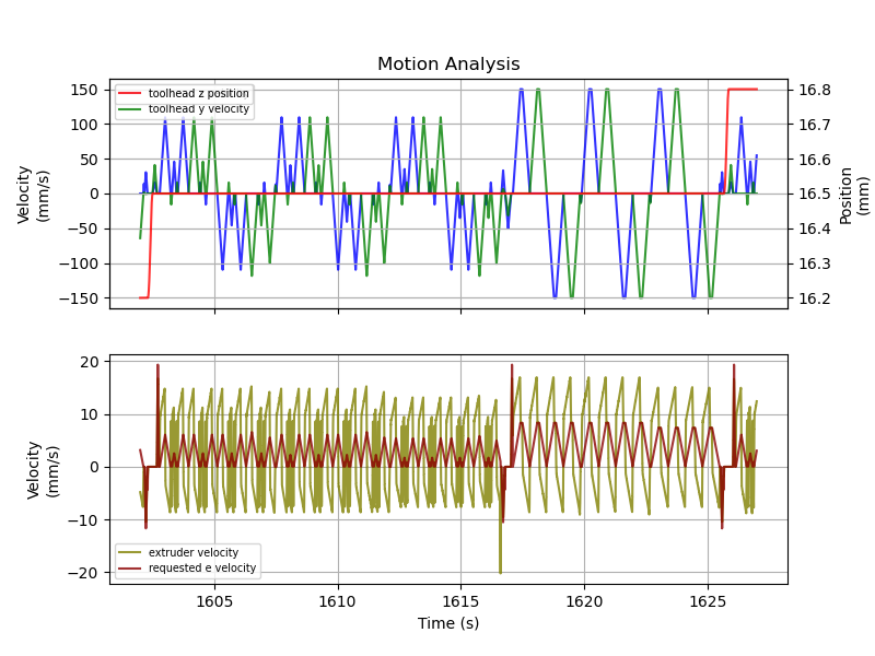
FYI, I've been able to use the new motion analysis tools (#4555) to look at the low-level movements Klipper produces during a standard pressure advance test. Here's a graph of a single Z layer (this is with a TUNING_TOWER FACTOR=.020): One thing interesting that I saw is the retraction spike around time 1616. Zooming in we see: The retraction spike is actually due to an instantaneous extruder velocity change - the toolhead moves in the same direction after it stops extruding - and Klipper thus allows up to the default 1mm/s instantaneous extruder speed change. However, the PA system still has to cope with that change and it therefore needs to extract 0.330mm over the smooth time window (40ms) which thus leads to a spike. It may be the case that Klipper's default 1mm/s for Interestingly, the requested retract and later unretract that occur a few moments later are smoothed out much more gracefully. -Kevin |

|
Hello, It looks like there hasn't been any recent updates on this Best regards, ~ Your friendly GitIssueBot PS: I'm just an automated script, not a human being. |
|
Ping for for the bot that this is still open. I have been happily using the modified smoothing but haven't really had time to focus on experimentation in a while. I'll still try to get a good test case with pics when I do. |
|
Hello, It looks like there hasn't been any recent updates on this Best regards, ~ Your friendly GitIssueBot PS: I'm just an automated script, not a human being. |
|
Ping |
function

Idea developed by @richfelker in Klipper3d#4442. Patch provided by @Piezoid.
function

Idea developed by @richfelker in Klipper3d#4442. Patch provided by @Piezoid.
Klipper's pressure advance smoothing smooths out not just the speed-dependent degree of advance that's added to the extruder position, but the whole extruder position function with that term added. This results in some surprising behaviors; for example
set_pressure_advance smooth_time=0.1 advance=0andset_pressure_advance smooth_time=0.1 advance=0.000001differ drastically in outcome due to the smoothing window only being applied when
advanceis nonzero, but having effects orthogonal to advance.Now I've come across a behavior which I think is far more problematic: Due to asymmetry of the constant-acceleration position function, which I'll denote
around a point
t, averaginge0(t-delta)ande0(t+delta)does not givee0(t), but a value offset frome0(t)bya/2 * delta². If I did the math correctly, integrating this against the triangle window function withdeltarunning from 0 to half smooth time gives an offset on the order ofa/6 * hst², which is significant in magnitude at high acceleration and/or smooth time. In fact it can be far larger than the pressure advance offset itself. This offset only applies during acceleration (and deceleration, in reverse); while crusing at the nominal speed it's zero. This results in overextrusion when first starting to accelerate, followed by underextrusion, becoming most severe when first starting to decelerate.For an idea of the scale, take 20k acceleration and 40 ms smooth time. At 30 spatial mm per E-mm (0.2 layers, 0.4 width, 1.75 filament), that comes out to 666 E-accel, yielding an offset of 111*0.02² or 0.0444 mm. At an advance constant of 0.05, that's on the same order of magnitude as the advance itself (comparable to the advance at spatial velocity of 30 mm/s).
I have not performed rigorous testing, but I did patch Klipper to smooth only the advance term, not the base extruder position function, and the results were very good:
These are all with my settings of
advance=0.05andsmooth_time=0.01where I didn't even expect the change to make a large difference.The text was updated successfully, but these errors were encountered: