Tutorial
In order to run LTLMoP, you will need a map and a specification. The following tutorial will show you how to create a map and a specification. From there, you can choose your robot and run your experiment.
Before you start using LTLMoP, please make sure you have installed all the dependencies here. To start LTLMoP, open cmd on Windows or terminal on Linus and Mac. Go to the LTLMoP/src directory. Start LTLMoP by running
python specEditor.py
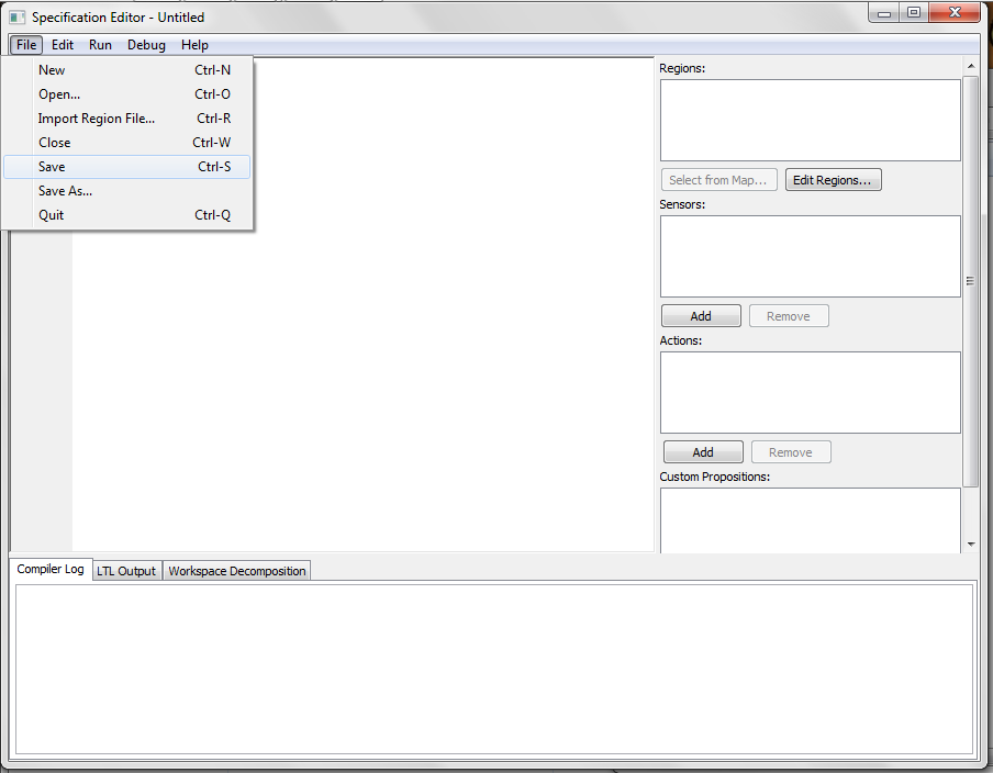
Once the LTLMoP GUI popped up, go to File > Save and give your project a name. We advise you to start a new folder and save your project there. Here our project will be called tutorial.spec and saved inside LTLMoP > src > examples > tutorial folder.

There are two ways to add a map to our experiment. You can either create a new map or import an existing map from other experiments. The two methods are both described below. Please follow the existing map method if you want to speed up this step.
Now we can create the map for our mission. Click the Edit Regions... button on the right and a new GUI will pop up.

Here is the description of the tools on the left:
| Tools | Description |

|
Select objects in the editor. |

|
Create a polygon with multiple points. Click on the starting point to close the polygon. |

|
Draw a rectangle by clicking on two arbitrary points in the editor. |

|
Add a point(vertex) to rectangles or polygons in your map. Click on the edge of the object that you want to add a point. |

|
Remove a point(vertex) on rectangles or polygons in your map. Click on your selected point to remove a vertex on the object. |

|
Add calibration points to your map. You are required to add at least three calibration points in case of using a physical robot or Gazebo robot simulator. These points should be as far as possible from each other. |
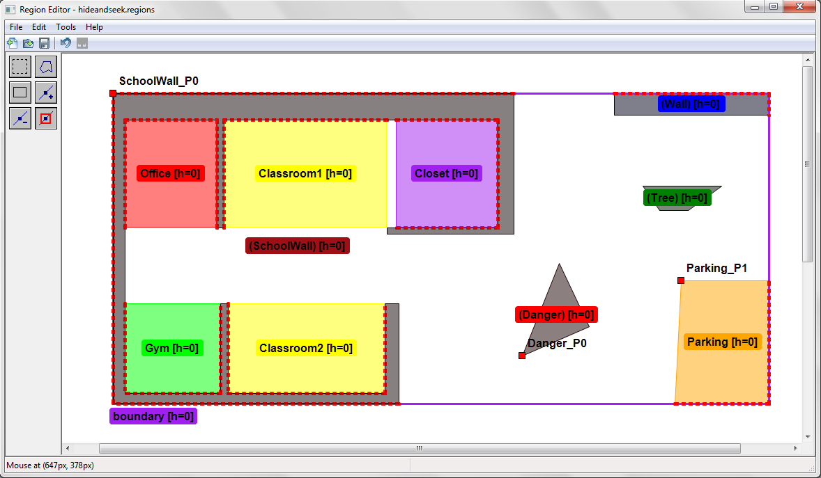
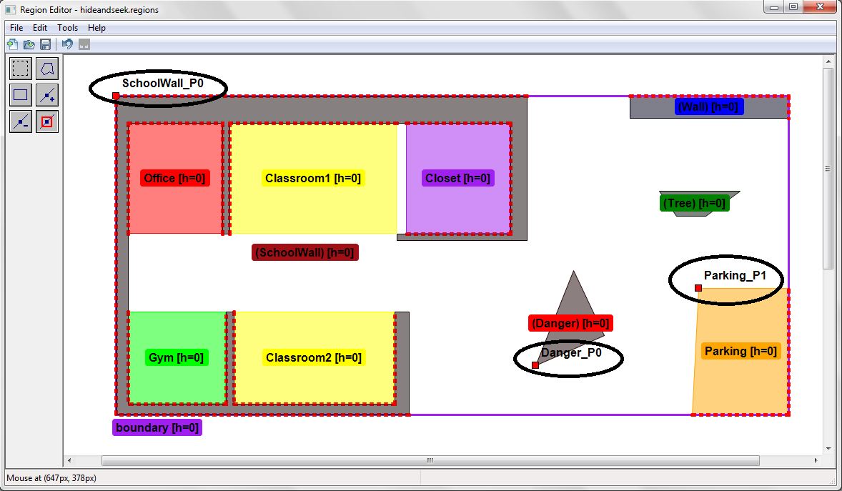
Here is an example of a map created. This region is located under LTLMoP > src > examples > hideandseek > hideandseek.regions.
Note that:
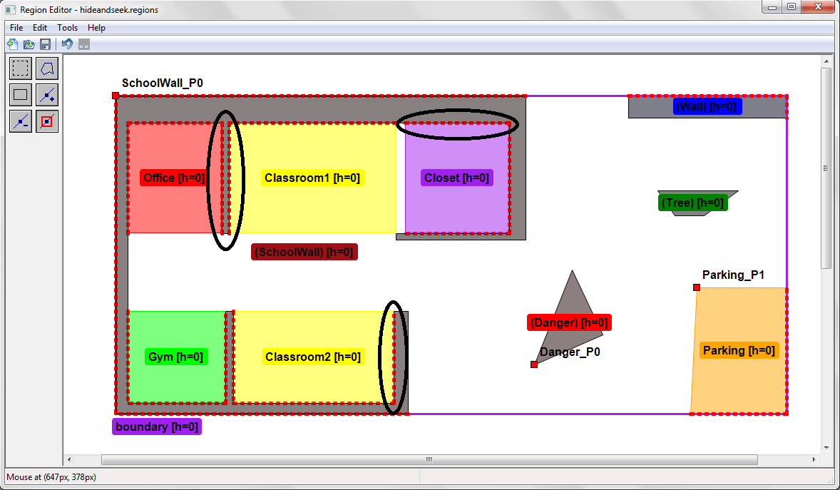
1. Please make sure all the regions are connected. If you see a red dotted line between two regions, this means the two regions are connected. (* If you intend to have your region connected to the white space, the red dotted line will not be shown.) Here we have circled some of the connections in black.
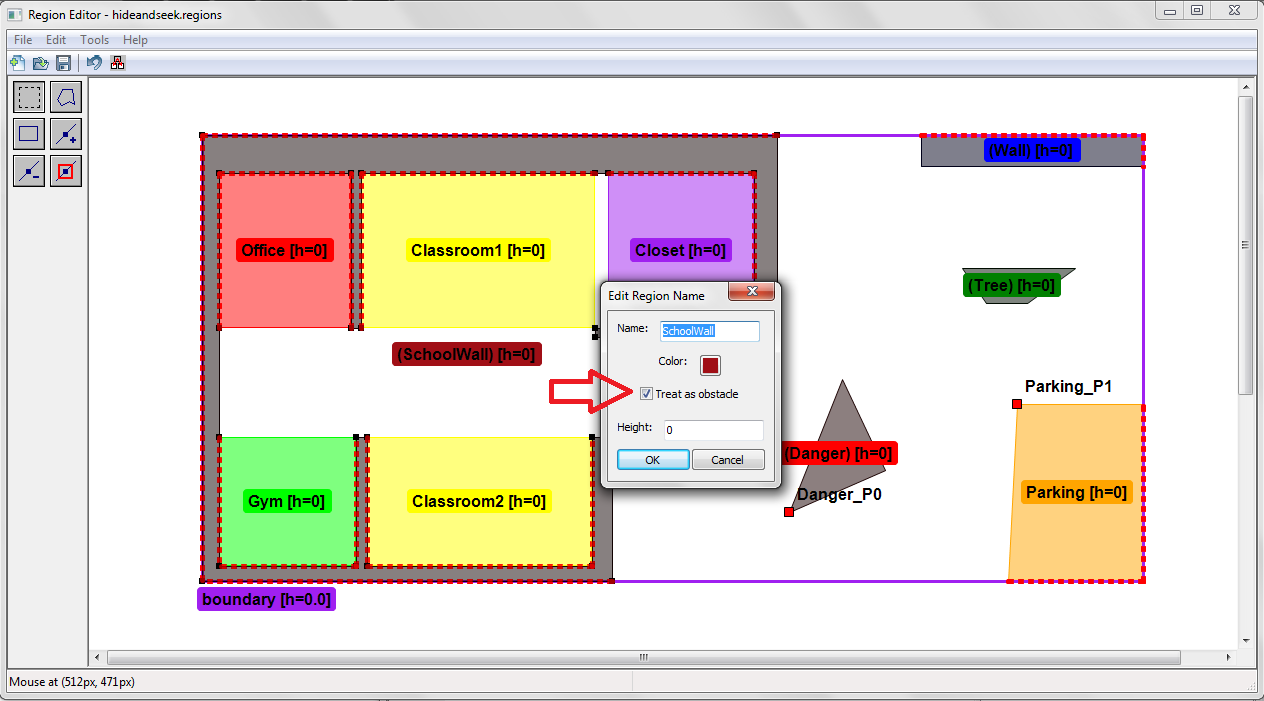
2. Obstacles could be added in the map. This is done by double clicking on a region intended to be an obstacle. Check the Treat as obstacle box and click ok to save it. Double check that the region turns grey, indicating it is an obstacle.
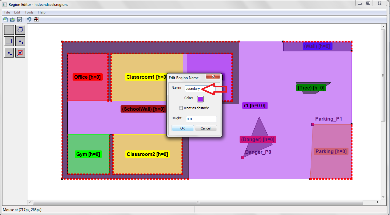
3. A boundary is required for the map. This could be created using the polygon tool and goes around all the regions. Then rename the region as boundary by double clicking on the region.
4. Be sure to add 3 calibration points to your map.
Once your are done, save the map and close the GUI.
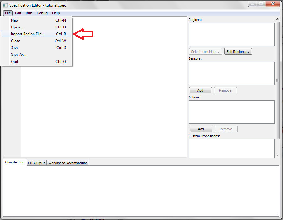
Alternatively, we can import regions from other examples. To do so, go to File > Import region file... to choose our .regions file.
Here we use the map from the preloaded hideandseek example under LTLMoP > src > examples > hideandseek folder.
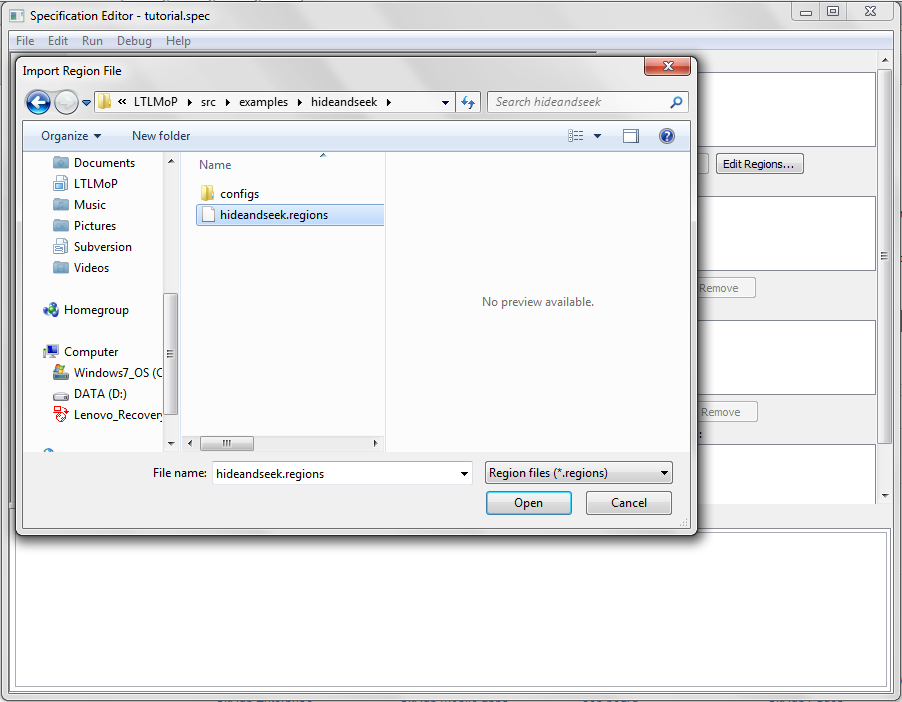
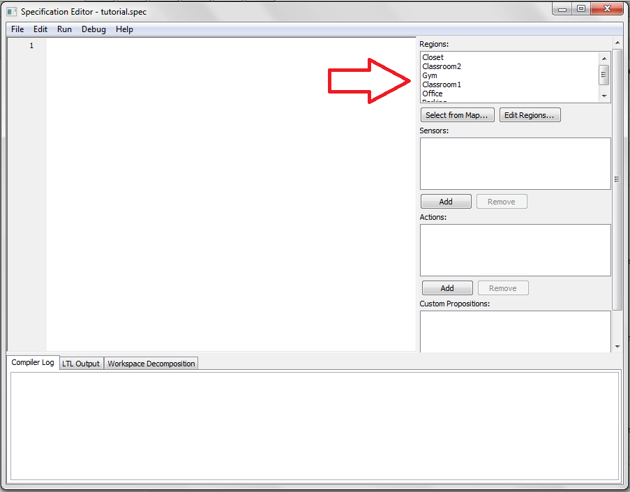
Click Open to import the file. To check that we have successfully imported our map, you should see all the region names being shown on the left.
Now we come back to the main GUI and start writing our specification. For documentation on how to write a specification, please download this file. Using our map above, we will ask the robot to alternate between Classroom1 and parking. The specification will be as shown below:
go to Classroom1
go to Parking
and this is how it looks like in our specification editor.
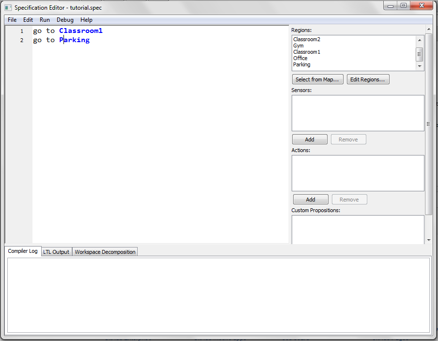
Do not add any punctuation in your specification. This may cause compilation errors later on.
LTLMoP is currently integrated with a variety of robots. To simplify our tutorial here, we will use the basicSim robot that comes with LTLMoP. BasicSim robot is a point robot operating in a simulated environment. In this case, it will be our simulation window later on. If you are interested in using LTLMoP with other robots, please go to our ASL wiki for more information.
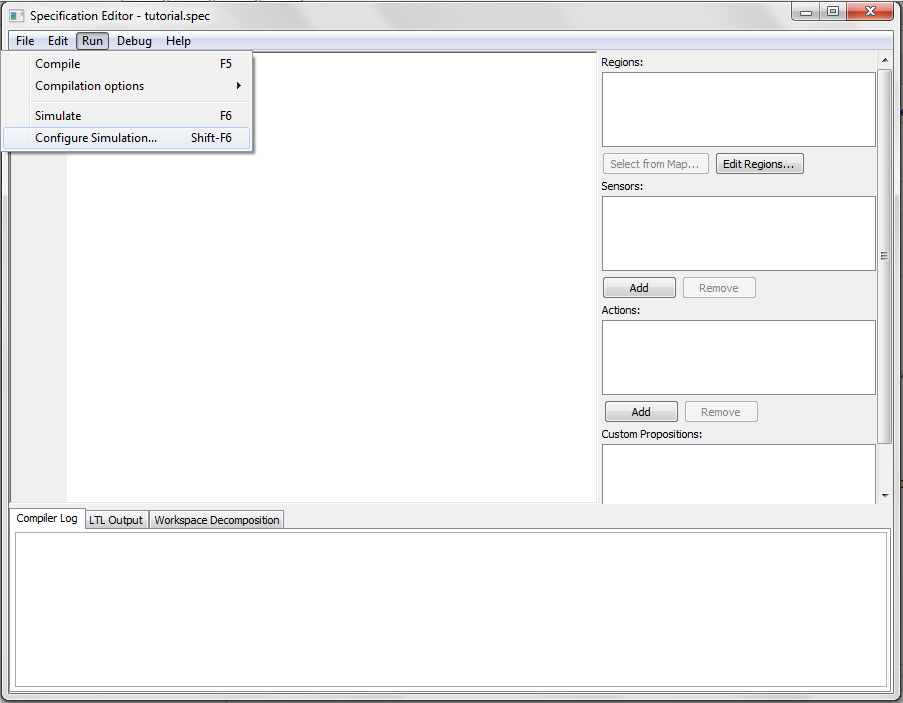
First go to Run > Configure Simulation ... or hit Shift + F6 .
We will put our experiment name to be tutorial.(1)
Note that the panel on the left allows you to set up a new experiment without deleting your current one.(2)
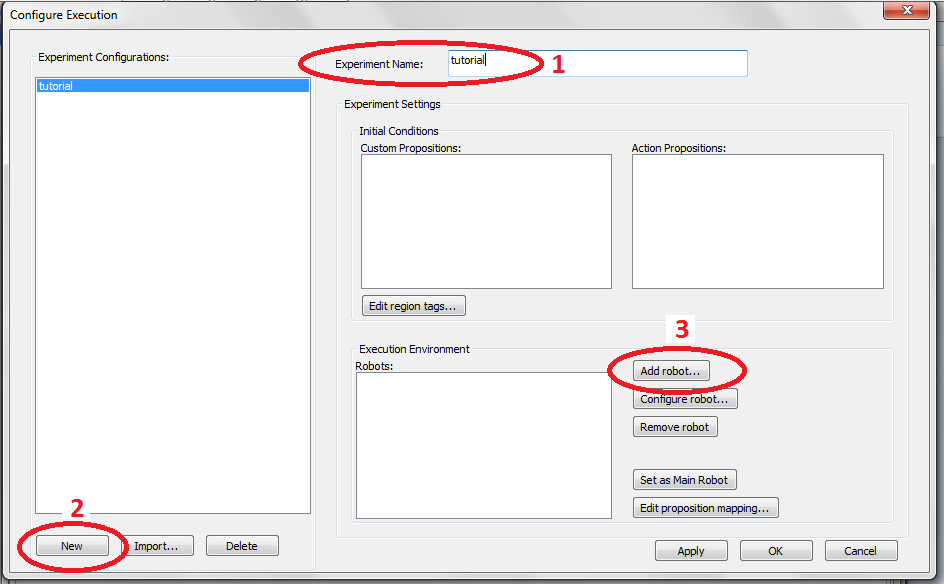
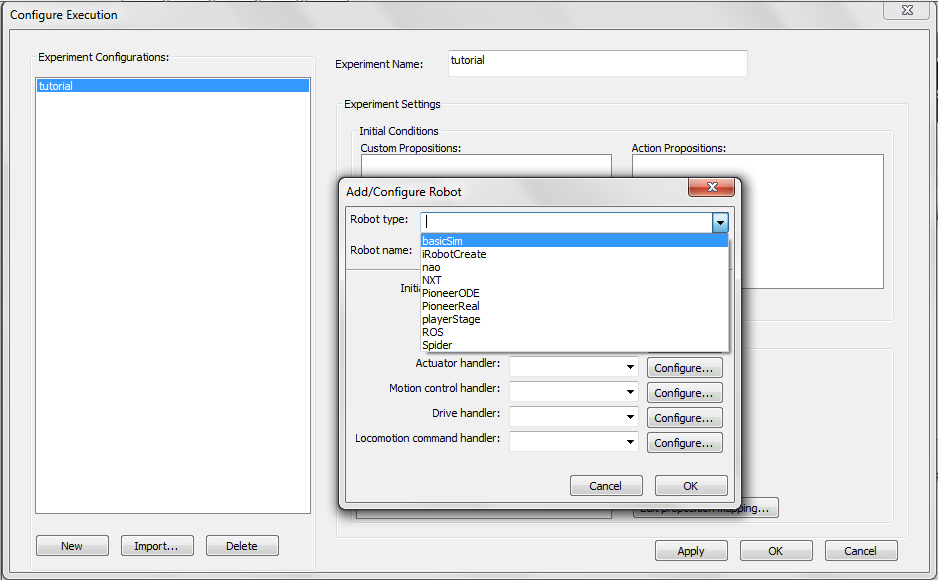
Then we need to choose our robot. Under Execution Environment, click on the Add Robot button. Another GUI will pop up.(3) Here we will choose basicSim to be our robot. All the other handlers will be filled in automatically.
Now click on Configure for the Initialization Handler.
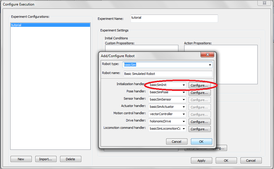
Choose a starting region. We will choose Classroom1 here.

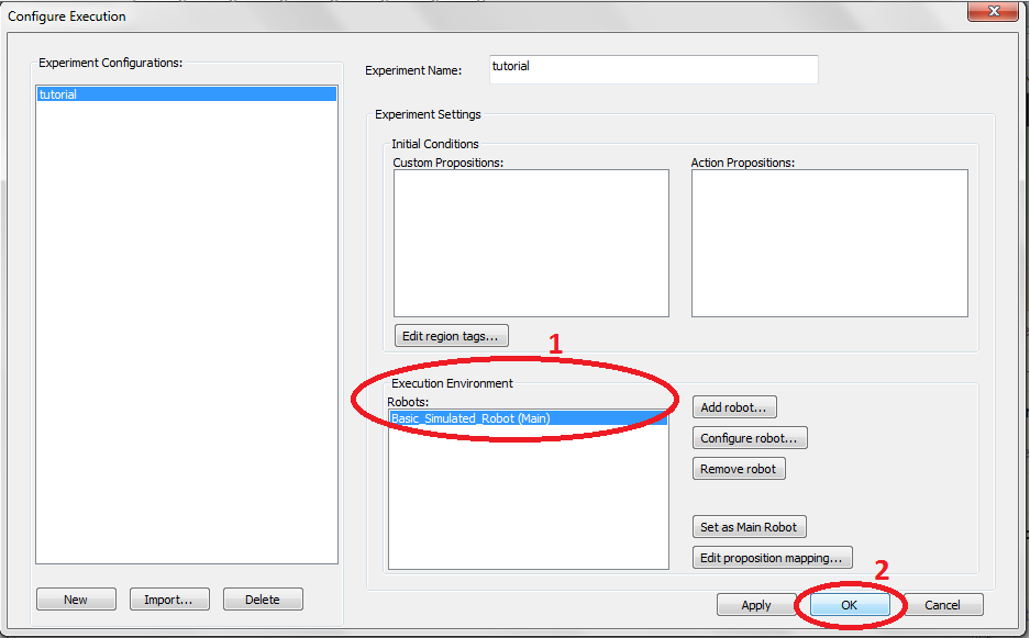
Click OK to close the Configure init.basicSimInit window. Click OK again to add our robot. A robot will now be shown here. (1) Click OK again to close the Configuration window and return back to the main GUI.(2)
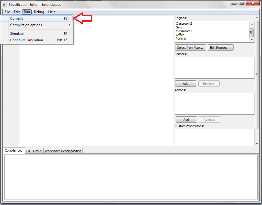
Once a robot is chosen, go to Run > Compile or press F5 to compile our specification.
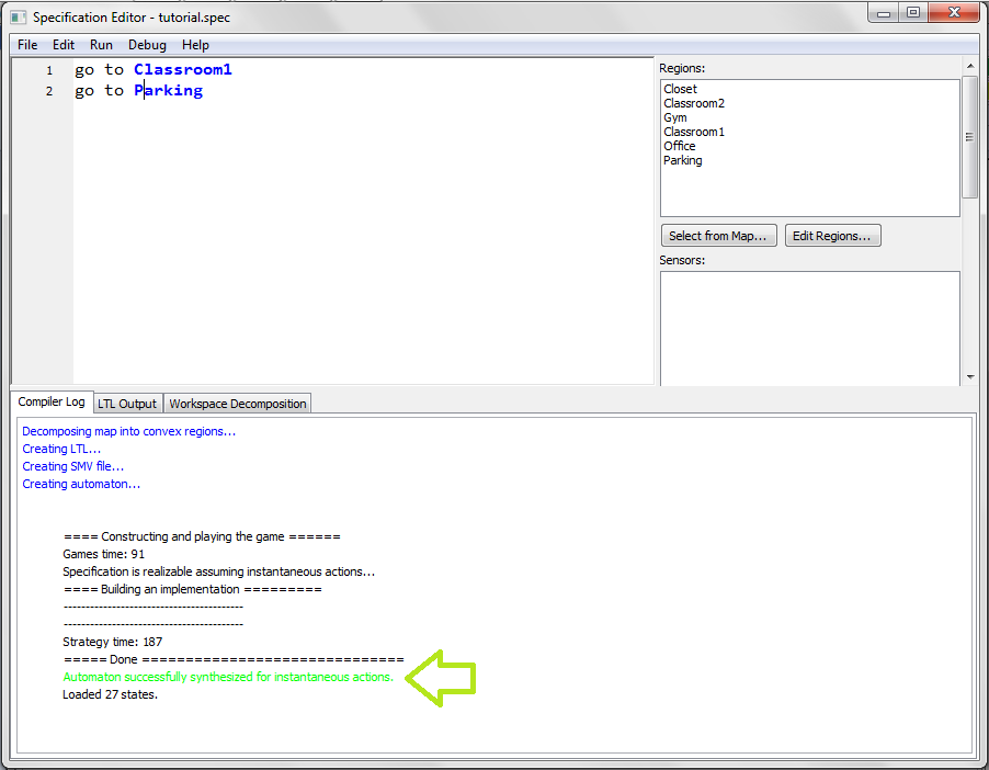
Here it shows that the compilation is successful.
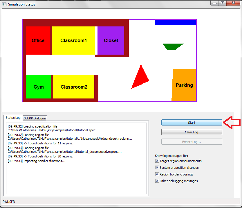
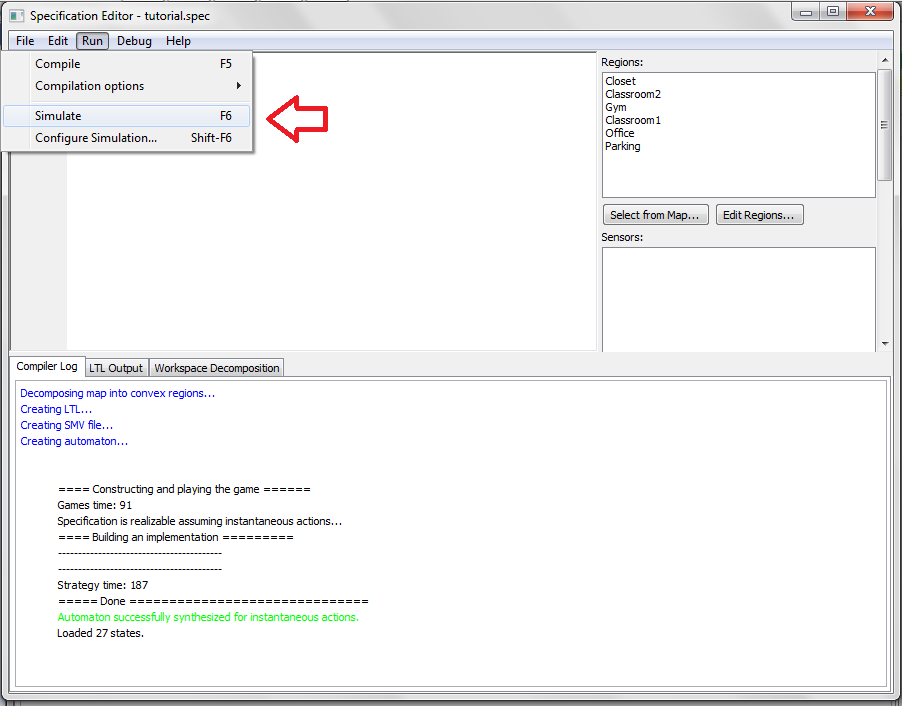
With a successful compilation, we will run our experiment. Go to Run > Simulate... or press F6 to start our experiment.
A new simulation window will pop up. Click Start to run our experiment. Enjoy!